Simulink model for Door bell and temperature control fan.
AIM:
- To make the doorbell block model using Simulink.
- To create the block model for a temperature-controlled fan.
OBJECTIVES:
- Using the solenoid block in Simulink to create a doorbell model, operate the model in the Simulink, and plot the result.
- To make a model of a temperature-controlled fan system, which will make the fan run only if the temperature exceeds 25 degrees the fan will turn ON. To operate the model and make a plot for the same.
INTRODUCTION:
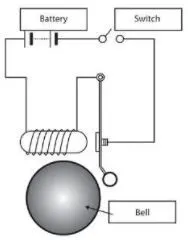
The doorbell is an electro-mechanical circuit that includes both the electrical and mechanical parts. All these components work together in the circuit to get the final results.
The components that are used in the circuit are:
- Pulse generator
- Switch
- Battery
- Solenoid block
- Ideal translational motion sensor
- Scope
- Solver configuration.
All these components are available in the Simulink library.
BLOCK DIAGRAM FOR DOORBELL MODEL:
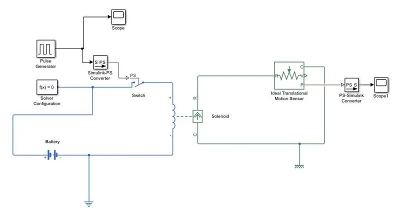
EXPLANATION:
- The input for the circuit is a pulse signal, that is generated using the pulse generator block in the circuit.
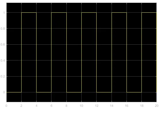
- This type of pulse signal input is given to the circuit. As we want pulse every after 2 seconds the signal is modified as per the requirement.
- This signal is connected to the switch, which is having a threshold less than the input signal so the switch will only get ON when the threshold crosses the switching threshold.
- The signal is further given to the solenoid in the circuit, the solenoid has a plunger which gets actuated as the signal strikes the solenoid. This causes the circuit to gets complete and the bell rings.
- To see the output we have connected the ideal translational motion sensor which records the motion of the plunger and the output can be seen in the Scope.
OUTPUT:
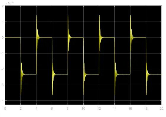
- It can be seen that the disturbance in the signal is due to the striking of the plunger on the bell and the sound is created. This output verifies that the circuit is working as required.
BLOCK DIAGRAM FOR THE FAN CONTROLLED BY THERMISTOR
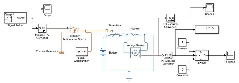
The components that are used in the circuit are:
- Signal builder
- Controlled temperature source
- thermistor
- resistor
- battery
- Voltage sensor
- Switch
- Scope and display.
EXPLANATION:
- The input to the circuit is given by a signal builder unit, in a signal builder unit we can modify the input pulse according to our requirement. So as we require that the fan should turn ON only if the temperature increases 25 degrees. Based on this we have to modify the input signal.
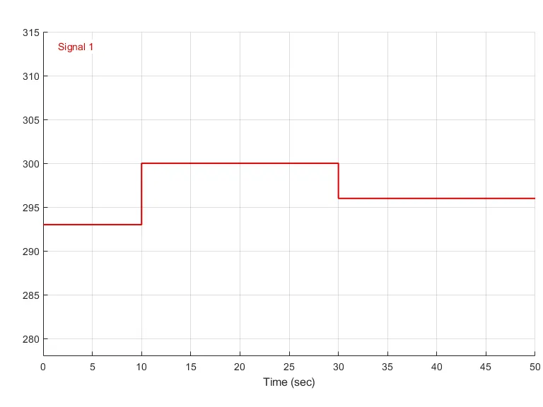
- The input given to the circuit shown in the graph clearly shows the relationship between the time and the temperature for the time duration of 50 sec. The temperature varies from 293K to 300K in the time duration of 0 to 30 sec, then remains constant at 296K for the rest of the time duration.
- As the requirement is that the fan should turn ON after 25 degrees the voltmeter is connected to the circuit, this voltmeter will give us the spike in the voltage when the temperature reaches 25 degrees.
- This spike is actually the threshold that the switch will get active and will give the output at the exact moment once the threshold is reached the fan will start.
OUTPUT:
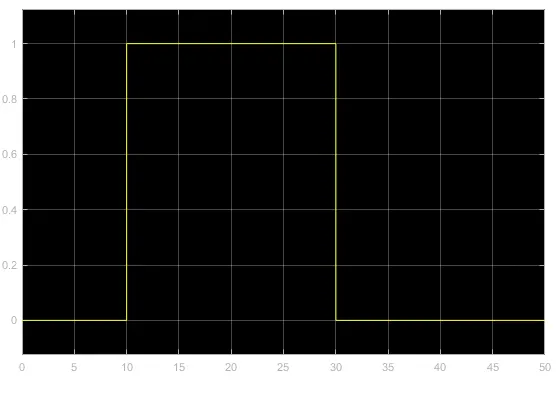
- From the output graph, it can be seen that there is no moment for fir 10 seconds, but the output reaches 1 from 10 to 30 seconds.
CONCLUSION:
- From the first circuit, we can conclude that the pulse is getting generated every after 2 seconds and the circuit is properly executed for the given input.
- In the second circuit, the fan was ON for the complete duration when the temperature was 25 degrees in the input and OFF during the other time hence we can say that both the circuits are perfectly working and are able to provide the desired output.