Week-4 Simulink : Control logic of a washing machine and gear shift logic
Control logic of a washing machine
A washing machine is a machine to was clothes, sheets and laundry. The process involves soaking, rinsing, washing and drying.
Parameters:
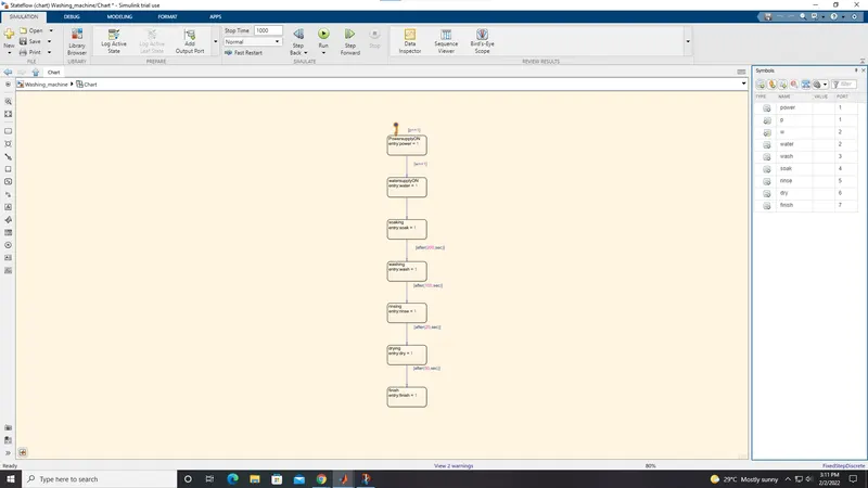
Soaking = 200 sec
Washing = 100 sec
Rinsing = 20 sec
Drying = 50 sec
Simulink model:
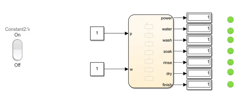
Stateflow chart:
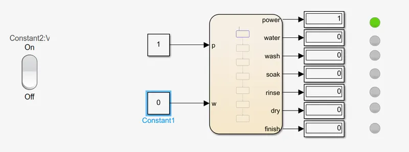
When water supply not available:
Blocks used:
- Rocker switch
- Constant
- Chart
- Display
- Lamp
Rocker switch:
The Rocker Switch block toggles the value of the connected block parameter between two values during simulation.
Constant:
Generates constant value.
Chart:
A Stateflow chart is a graphical representation of a finite state machine. States and transitions form the basic elements of the system.
Display:
Displays neumerical output.
Lamp:
This block displays color indicator for the input value.
Process:
The conditions for the washing machines is entered and the value for ON condition is 1 and OFF condition is 0. If the power supply is ON then the value is 1 and if the power supply is OFF then it is 0, similarlly this condition implies for all the parameters. Therefore when the power supply is ON water supply will become ON and soaking process takes place for 200 seconds, after soaking washing takes place for 100 seconds, after washing rinsing takes place for 20 seconds and after rinsing drying takes place for 50 seconds. After the parameters are conditioned in the chart block two constant blocks are connected to power and water, then a rocker switch is added to toggle between two values and it is connected to power because power only controls the whole system. Hence the control logic of a washing machine is created and the conditions are satisfied.
2. Gear shift logic:
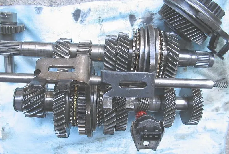
A transmission is a machine in a power transmission system, which provides controlled application of power. Often the term 5-speed transmission refers simply to the gearbox, that uses gears and gear trains to provide speed and torque block conversions from a rotating power source to another device.
5speed gear box:
Parameters:
Speed Range(kmph) Gear
0 to 15 1
16 to 25 2
26 to 40 3
41 to 60 4
Above 61 5
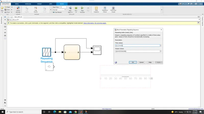
Simulink model:
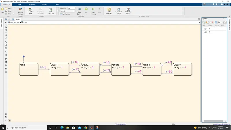
Stateflow chart:
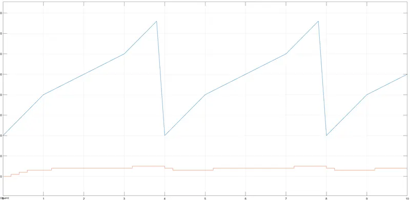
Output:
Blocks used:
- Repeating sequence
- Chart
- Scope
Repeating sequence:
This block shows the output of a repeating sequence of numbers specified in a table of time-value pairs. Values of time should be monotonically increasing.
Chart:
A Stateflow chart is a graphical representation of a finite state machine. States and transitions form the basic elements of the system.
Scope:
This block displays signals generated during simulation.
Working:
In the chart the state blocks are created and named as gears. when the gear is shifting from 1 to 2 the speed must be greatet than 15 and if its less it will stay in gear 1, similarlly when shifting from gear 2 to 3 the speed must be greater than 25 and from gear 3 to 4 it should be greater than 40 and from gear 4 to 5 it must be greater than 60. Symbol pane column is opened and s is named as input data and a is named as output data so there is 2 output port created and hence when ran we get the output signal which can be viewd from the scope. This simulation can also be performed using slider block which is used to increase the value in constant block in real time while the simulation is running.