SIMULATION OF FORWARD KINEMATICS OF 2R ROBOTIC ARM, USING PYTHON PROGRAMMING LANGUAGE
AIM:
- To simulate the forward kinematics of 2R Robotic Arm using Python Program.
OBJECTIVE:
- Main objective is to create the plots at various angles up to which the arms can move, then to stitch all the plots sequentially together for generating a smooth animation. This animation will provide workspace (maximum possible reach of the end effectors) of the robotic arm.
INTRODUCTION:
- In general Kinematics refers to the study of Motion of an object, without considering the forces causing the motion.
- Forward Kinematics of robotic arm, refers the use of kinematic equation of robotic arm to compute the position of end effectors from the specified values of end effectors. This is used to study the motion of the robotic arm and also to compute the position of end effectors or Manipulators from specified values of joint parameters.
- This helps to figure out the workspace of that robotic arm. Workspace refers to the maximum possible reach of the end effectors connected to the robotic arm.
DETAILED CONTENT:
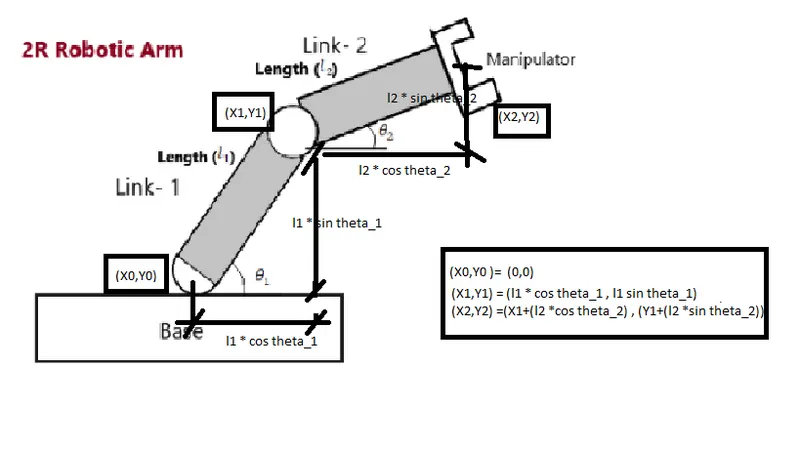
- The 2R Robotic arm, has two links (Link-1 & Link-2), which are connected by rotational Joint.
- In the Link-1,One end is connected to the base, having its co-ordinates as (x0, y0) and the other end is connected of Link-1 is connected to the link-2, having its co-ordinates as (x1, y1) detailed sketch of the joint parameters is given below.
- In the Link-2, as discussed one end is connected to link-1 having its co-ordinates as (x1, y1), The other end of link-2 is connected to the manipulator or the end effecter (x2, y2).
- The below image with the parameters will give the detailed idea of the 2R robotic arm,
Assigning the length for the two links:
- Length of Link_1, l1 = 3 meters
- Length of Link_2, l2 = 1 meters
Assigning the input for the co-ordinates:
- ( x0 , y0 ) = (0 , 0) ; As it is the base of the robotic arm (Refer the above figure)
- ( x1 , y1) = ( l1 * cos theta_1 , l1 * sin theta_1) ; (Refer the above figure)
- (X2, Y2) = ( (X1 + (l2 * cos theta_2)) , (Y1 + (l2 * sin theta_2)) ; (Refer the above figure
Idea Used for Ploting the motion of the Robotic arm:
- As described in the objective, Program will be in such a manner to plot the images for every 10 degree rotation, (0 degree to 90 degree) of both the links. To the every 10 degree rotation link-1, the link-2 which is connected to manipulator will rotate 90 degree.
- If link-1 is in 0 degree, link-2 will rotate from 0 degree to 90 degree, Likewise the plot will be captured for every 10 degrees rotation of link-2, that is for one position of link-1, 10 plots of link-2 will be captured in the following degree, ( 0, 10, 20, 30, 40, 50, 60, 70, 80, 90)
- Thus for each position, link-1 , 10 plots will be created with the position of link-2.hence in total 100 plots will be captured.
- Those plots will be stitched together in a proper sequence for creating smooth animated using image magic software.
PYTHON CODE WITH STEPWISE EXPLAINATION:
"""
CREATING ANIMATION FOR THE PLOT OF FORWARD KINEMATICS OF 2R ROBOTIC ARM
HERE, THE 2 LINKS ARE CONNECTED WITH THE ROTATIONAL JOINT
ONE END OF LINK-1 ONE IS CONNECTED TO THE BASE (ROTATIONAL JOINT), AND OTHER END OF LINK-1 TO THE OF LINK-2.
ONE END OF LINK-2 IS CONNECTED WITH THE LINK-1 (ROTATIONAL JOINT), AND OTHER TO THE MANIPULATOR
AS THIS CODE IS DESIGNED IN SUCH A MANNER, THAT BOTH THE LINK-1 & LINK-2 CAN ROTATE
AND THIER MOVEMENT CAN BE PLOTED AND TOGETER ANIMATED
"""
#IMPORT THE REQUIRES MODULES / LIBRARY

import math
import matplotlib.pyplot as plt

#LENGTH OF LINK-1 AND LINK-2 IS ASSUMED AS

l1=3
l2=1
"""
AS THIS PROGRAM WILL PLOT THE IMAGES FOR EVERY 10 DEGREE ROTATION OF LINK 1, THAT IS FROM (0 DEGREE TO 90 DEGREE) OF BOTH THE ,LINKS
TO THE EVERY 10 DEGREE ROTATION LINK-1, THE LINK-2 WHICH IS CONNECTED TO MANIPULATOR, WILL ROTATE 90 DEGREES
IF LINK-1 IS IN 0 DEGREE, LINK-2 WILL ROTARE FROM 0 DEGREE TO 90 DEGREE, THE PLOT WILL BE CAPTURED FOR EVERY 10 DEGREES ROTATION OF LINK-2
THAT IS FOR ONE POSITION OF LINK-1, 10 PLOTS OF LINK-2 WILL BE CAPTURED IN THE FOLLOWING DEGREE
( 0, 10, 20, 30, 40, 50, 60, 70, 80, 90)
THUS FOR EACH POSITION, LINK-1 , 10 PLOTS WILL BE CREATED WITH THE POSITION OF LINK-2.
HENCE IN TOTAL 100 PLOTS WILL BE CAPTURED AND THEN THOSE PLOTS WILL BE ANIMATED USING IMAGE MAGIC
"""

# NO OF TIMES THE FOR LOOP SHOULD BE EXECUTED
n=10

# STATING POSITION OF THE LINKS AND ENDING POSITION OF THE LINKS
# THE ANGLES DEFINED MUST BE RADIANS FOR ACCURACY
theta_start= 0
theta_end= (math.pi)/2

# EMPTY ARRAY TO STORE THE VALUE OF BOTH THE ANGLES
theta_1=[]
theta_2=[]

# DEFINING LOOP FOR THE ORIENTATION OF BOTH THE LINKS TO BE 10 DEGREE ANGLE, GIVEN INPUT TO THE ANGLES (theta_1) and (theta_2)
for i in range(0,n):
	x = theta_start+i*(theta_end - theta_start)/9
	theta_1.append(x)
	theta_2.append(x)


# THE ORIGIN POINT OF LINK-1
x0= 0
y0= 0
# THIS INTEGER IS DEFINED FOR ASSIGNING FILE NAME, FO STITCHING THE PLOTS IN A SEQUENCE, WHICH WILL BE EASILY USED FOR ANIMATION
ct=0

# DEFINING NESTED FOR LOOP, THIS IS TO PLOT FOR EVERY LINK-1, LINK-2 MUST HAVE 360 DEGREE ROTATION AND PLOT FOR EVERY 30 DEGREES
for t1 in theta_1:
	for t2 in theta_2:
		# POSITION OF THE 2ND END OF LINK-1 AND THE STARTING END OF LINK-2
		x1= l1 * math.cos (t1)
		y1= l1 * math.sin (t1)
		# POSITION OF THE MANIPULATOR OR THE 2ND END OF THE LINK-2
		x2=x1 + l2 * math.cos (t2)
		y2= y1 + l2 * math.sin(t2)
		# PLOTING EACH FIGURE SEPERATELY AND ASSIGING LIMITS AS THIS ROTATES 360 DEGREES
		plt.figure()
		plt.plot([x0,x1],[y0,y1],linewidth= 5)
		plt.plot ([x1,x2],[y1,y2], linewidth =5)
		plt.xlabel ('X-AXIS IN METERS')
		plt.ylabel ('Y-AXIS IN METERS')
		plt.title ('FORWARD KINAMATICS OF 2R ROBOTIC ARM')
		plt.xlim(0,4)
		plt.ylim(0,4)
		# SAVING THE FILE NAME (PLOTED IMAGES IN ORDERLY MANNER)
		ct = ct+1
		filename=str (ct)+'.png'
		plt.savefig(filename)
OUTPUT & RESULT:
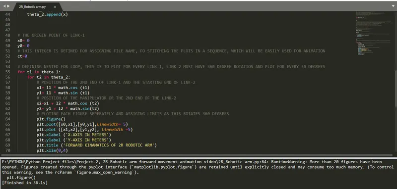
- As 100, Images are being saved at the same time, the warning output is displayed.
- Thus the, 100 images which is in the proper sequence is moved to a seperate folder, then Using image magick software the animation is made and the link of the animation file is given below,
https://drive.google.com/drive/folders/1G-Hfljzi-97pTNlImasHQqgntoaRUrHM?usp=sharing
CONCLUSION:
Thus, Using PYTHON PROGRAM, the forward kinematics of 2R Robotic Arm has been simulated. Finally, The animation helps to visualize the workspace (maximum possible reach of the end effectors)of that robotic arm.