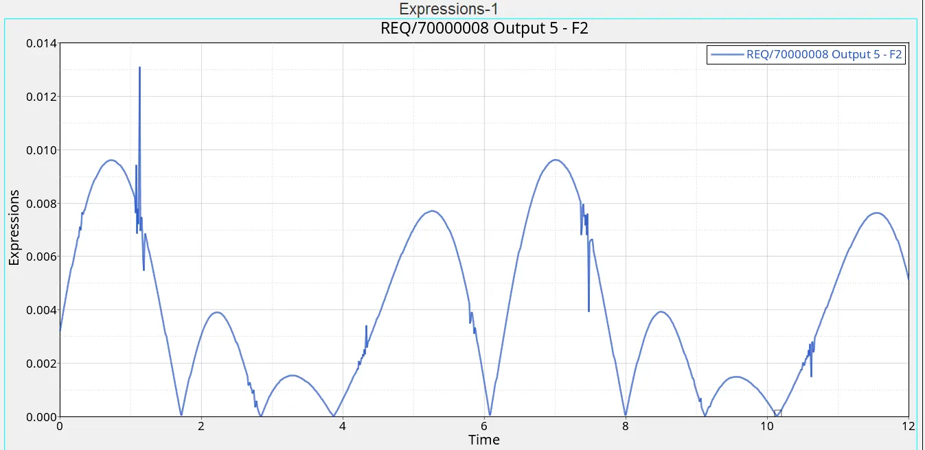
Simple Beam Engine Mechanism using Altair Motionview
https://drive.google.com/file/d/1TZNg15wL6raQtUirgyWtxkwnO9_Lrt9H/view?usp=sharing
BEAM ENGINE
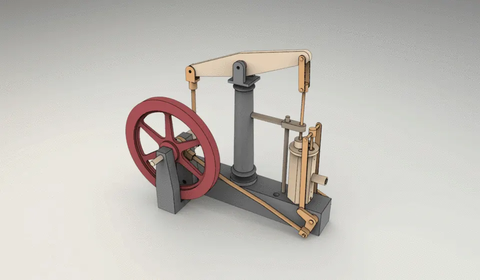
HOW IT IS RELATED TO FOUR BAR MECHANISM
Before we continue with the explanation of the mechanism , we need to explain some terms and concepts regarding this mechanism breifly :
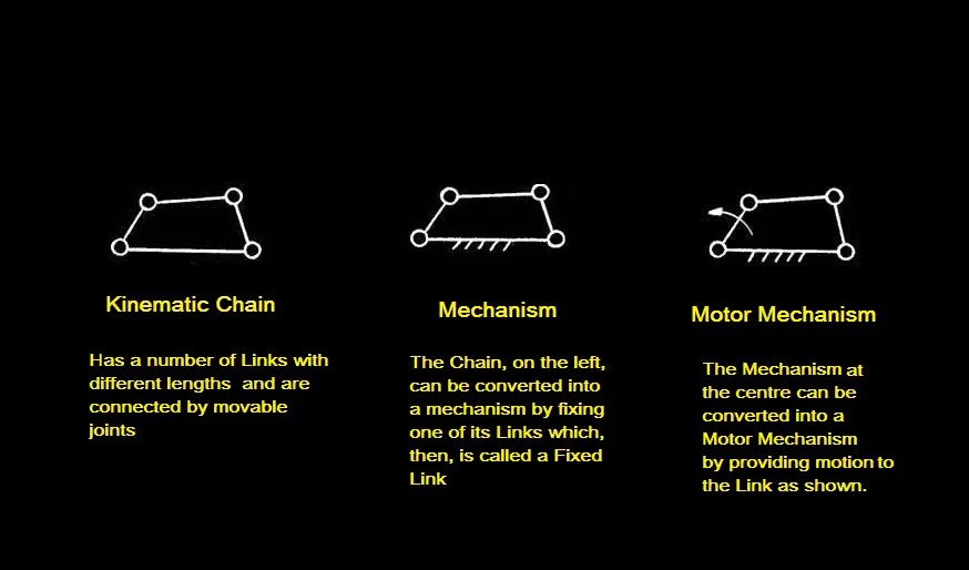
- Succesfully constrained motion : A kinematic pair is said to be succesfully constrained when the relative moiotn between its links in a definite direction , not by itself but by some other means .
A good example of successfully constrained motion is piston reciprocating inside a cylinder in an internal combustion engine.
Normally, when a piston is placed in a cylinder, it may undergo reciprocating motion (upward and downward motion) and turning motion, depending on the external forces applied. It is incompletely constrained.
However, if the piston is connected to a connecting rod, its motion is successfully constrained i.e., it can only undergo only reciprocating motion inside the cylinder. Here, some other means (i.e., connecting rod) is used for successfully constraining the motion of the piston.
- Kinematic pair : The two links form a pair when they are in contact with each other and the relative motion between them is succesfully constrained .
- DOF : It is the number of inputs required to describe the configuration of mechanism of all the links of the mechanism with respect to the fixed link at any given instant .
- Grublers equation :
Number of degrees of freedom of a mechanism is given by
F = 3(n-1)-2l-h. Where,
F = Degrees of freedom
n = Number of links = n2 + n3 +……+nj, where, n2 = number of binary links, n3 = number of ternary links…etc.
l = Number of lower pairs, which is obtained by counting the number of joints. If more than two links are joined together at any point, then, one additional lower pair is to be considered for every additional link.
h = Number of higher pairs
NOTE : One tertiary joint is equal to two binary joints , One quaternary joint is equal to three binary joints .
- Types of joints
On the basis of relative motion between the links :
- Sliding pair : The two elements have a sliding motion relative to each other. Example: Piston and
cylinder pair.
- Rolling Pair : When one element is free to roll on another element. Example: The belt and pulley
surfaces constitute rolling pair.
- Turning Pair : When the two elements are connected such that the element revolves about the
other element. Example: Shaft rotates in the bearing rotation of a crank in a slider
crank mechanism.
- Screw Pair : In this type the contacting surface is having threads. It is also called a helical pair
one element turns about another element by means of thread only.
Example: A bolt and nut arrangement screw jack for lifting heavy weights.
- Spherical Pair: One element is in the form of sphere and turns about the fixed element;
Example: ball and socket joint
On the basis of type of contact between the elements :
- Lower pair : If a pair motion has surface contact between the elements. Example:
Piston reciprocating in a cylinder.
Shaft rotates in a bearing. (Contacting surfaces are similar)
- Higher pair : If the pair motion has a line or point contact between them , then it is called higher pair . Example: Cam and follower. (Contact surfaces are different.)
Inversion of mechanism : The method of obtaining different mechanism by fixing different links in a kinematic chain is called inversion of mechanism .
WHAT IS BEAM ENGINE ?
It is a type of steam engine where a pivoted overhead beam is used to apply the force from a vertical piston to a vertical connecting rod.
Applications :
- This type of mechanism is mostly used in oil rigs to move out the oil from beneath the Earth .
- This mechanism was mostly used in steam engines but nowadays it is used in water pumps, oil rigs , specifically
designed sawing machine etc.
Parts of Beam Engine
- Crank : Machines of several types of arms or levers for imparting rotary or oscillatory motion to a
rotating shaft. One end of the crank being fixed to the shaft and the other end is receiving
reciprocating motion from the hand, connecting rod, etc.
- Lever : It is a simple machine consisting of a beam or rigid rod pivoted at a fixed hinge, or fulcrum . A lever is a rigid body capable of rotating on a point on itself.
- Base support : It is fixed on the floor and it supports the lever while transmitting the motion during oscillation of the lever at the pivot location which is mostly connected to the piston that oscillates with it .
- Connecting Rod : A connecting rod is a link which connects a lever to a crank or crankshaft in a beam engine.
Together with the crank, it forms a simple mechanism that converts rotary motion into reciprocating motion. A connecting rod may also convert reciprocating motion into rotating motion.
Links and Pairs used
-
Links -
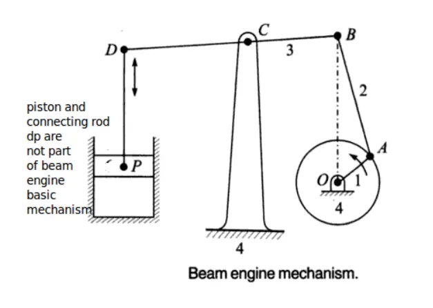
Link 4 OC (frame)
Link 1 OA (Crank)
Link 2 AB (connecting Rod)
Link 3 BCD (lever)
Pairs -
Turning Pair = Frame OC & Crank OA
Turning Pair = Crank OA & Connecting Rod AB
Turning Pair = Connecting Rod AB & lever BCD
Turning Pair = Frame OC & lever BCD
Working
This mechanism is an inversion of four bar chain . It has four turning pair. It consists of frame OC which is fixed and on which all other elements are fitted. The Crank is fixed at pt. 'O' at frame. The crank rotates about pt.'O' . Other end of crank is connected to connectin rod AB. Other end of connecting rod AB is linked to one end of lever. The lever is pivoted at pt 'C' other end of lever 'D' is attached to piston -cylinder mechanism as shown. As the crank starts rotating this motion is transmitted to lever by connection rod. As crank continues to rotate the lever starts to oscillate about pt. 'C', this oscillatory motion is transmitted to piston & cylinder.
Calculation
*** VERY IMPORTANT ***
If the model has 0 or less than 0 degrees of freedom using grublers equation , it will be called a locked mechanism ( structure ). If the model has one or more degrees of freedom then the model will need one or more drivers to operate them precisely .
Calucalting DOF using grublers equation and calculating DOF in motionview is very similar .
Lets calculate DOF using Grublers Equation :
- Numer of links : binary ( 3) , ternary (1)
- Number of Lower pairs : 4
- Number of Higher pairs : 0
- Total DOF : 3*( 5-1) -2*(4)-0 = 1
As you can see , this is a compound mechanism ( mechanism in which more than 4 links are present ) , and most of the mechanisms have commonly 1 DOF , except some exceptions .
MODELLING BEAM ENGINE IN MOTIONVIEW
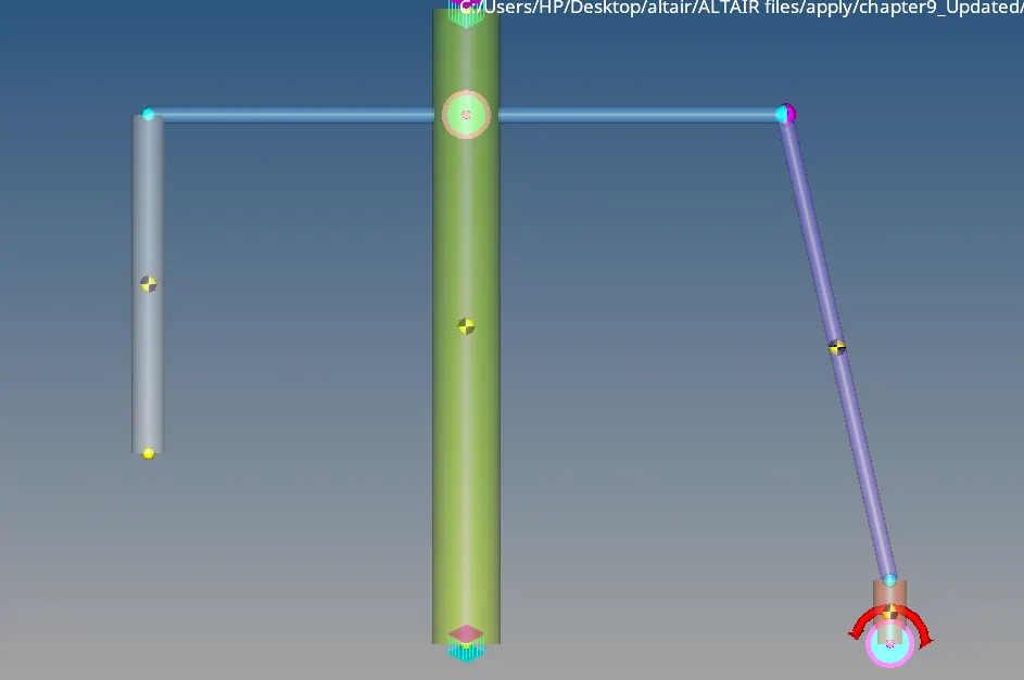
PROCEDURE
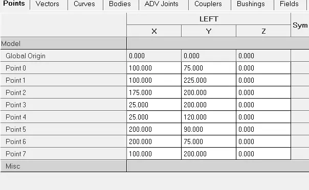
- Plot the points as shown in data summary .
- Now create Graphics of each links .
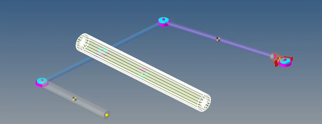
- Create bodies and assign them with their respective graphics .
- Assign joints to each of the links and attach one revolute joint between the ground and the crank .
- Assign the motion at the Revolute joint 4 , required to move the crank .
- Make sure the Gravity is in -ve Y direction , units in mm.
- Check model to know the DOF.
- No. of DOF in the system : 5*6 =30
DOF by Revolute joints : 4*5=20
DOF by Fixed Joint : 6
DOF by Ball joint : 3
DOF by Motion : 1
Total Dof of the system including constraints : 30-20-6-3-1=0
- Now , assign the output expressions at each joint . Use joint function to know the torque magnitude at each joints . Use Motion funcion to know the torque generated by Motion .
Syntax of Motion()
MOTION (id, jflag, comp, rm)
Arguments id
An integer specifying the identification number of the motion.
jflag
An integer flag specifying the motion connectivity marker at which the
forces and torques are computed.
0 = forces and moments at the I marker
1 = forces and moments at the J marker
comp
An integer value that specifies the component of the motion force to be
returned.
1 = Magnitude of the force
2 = x component of the force
3 = y component of the force
4 = z component of the force
5 = Magnitude of the torque
6 = x component of the torque
7 = y component of the torque
8 = z component of the torque
rm
The coordinate system in which the results are expressed. To return the
results in the global coordinate system, set rm = 0.
Syntax of Joint()
JOINT (id, jflag, comp, rm)
Arguments id
An integer specifying the identification member of the joint.
jflag
An integer flag specifying the joint connectivity marker at which the forces
and torques are computed.
0 = forces and moments at the I marker
1 = forces and moments at the J marker
comp
An integer value that specifies the component of the joint force to be
returned.
1 = Magnitude of the force
2 = x component of the force
3 = y component of the force
4 = z component of the force
5 = Magnitude of the torque
6 = x component of the torque
7 = y component of the torque
8 = z component of the torque
rm
The coordinate system in which the results are expressed. To return the
results in the global coordinate system, set rm = 0.
Results
Torque at Joint 0
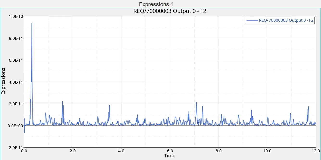
Torque at Joint 1
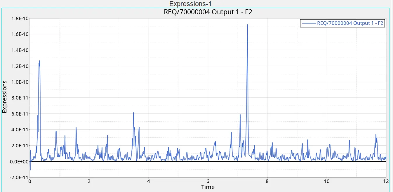
Torque at Joint 2
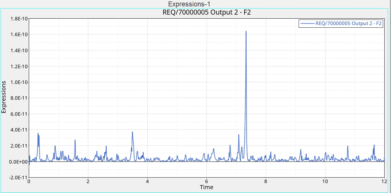
Torque at joint 4
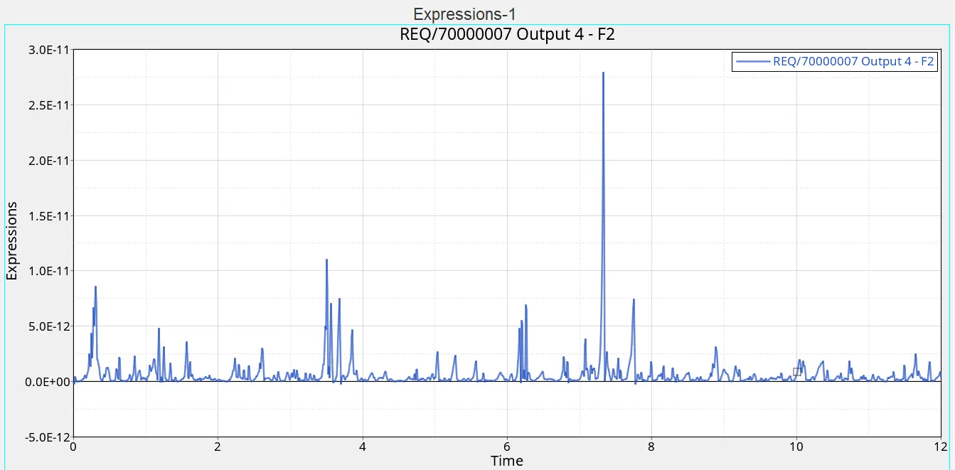
Torque generated by Motion