Section Modulus calculation and optimization
1. Objective:
- To calculate the section modulus for the previously designed hood and optimized hood.
- To come up with the new section that has improved section modulus of the previous section.
01. About Section module:
Section modules are the geometric property of a given cross-section used in the design of flexible members. Section modules depend only on the cross-section Shape of the beam or structure for symmetric section, the value of section modulus is the same foe both above and below of centroid of the cross-section. Asymmetric has two values for the top and bottom of the centroid, the maximum section modulus (Smax), and the Minimum section modulus (Smin).
Types of Module Section:
Elastic Section Modulus
PlasticsSectionModulus.
Significance of Section Modulus:
- Section modulus is an important factor for designing beam and flexible members.
- The higher the section modulus, the higher will be the resistance to bending.
- Easier to calculate strength and stress in beams.
- If two beams are made of the same material and the section modulus of two beams are being compared and vice versa, the beam with large section modules will be tougher and more capable to withstand larger loads
We know that stress (σ) in a beam or structure is given by
Section Modulus (S)
Equation S = I/y
Where
I = Moment of inertia
y = Distance between the neutral axis and the extreme end of the object.
From Equation
Stress (σ) = M/S
Thus from the equation, it can be said that the higher the section modulus, the higher will be the resistance to be bending.
02. The material used in Hood Design:
Stainless steel Grade-ASI302, Cold Rolled Y= 520 Mpa.
03. Section modulus of Inertial Hood Design :
Section-1
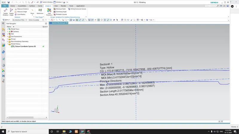
Info Analysis - Section Inertia Analysis


The mass properties are for hollow sections

Sect#  CG-XC     CG-YC     CG-ZC     CG-X      CG-Y      CG-Z      SL        SA
1      -172.811983715 -7318.169427856 -930.408707774 -172.811983715 -7318.169427856 -930.408707774 2.017756596e+03 40.355204074

Sect#  Max-MI    Max-X     Max-Y     Max-Z     Min-MI    Min-X     Min-Y     Min-Z     Max-RL    Min-RL
1      8.165367625e+05 0.000000000 0.983120607 0.182958663 3.411524472e+03 0.000000000 -0.182958663 0.983120607 478.550978669 18.757
545735

Sect#: Number of Section

CG-XC, CG-YC, CG-ZC: Center of Gravity (WCS) [mm]
CG-X, CG-Y, CG-Z: Center of Gravity (Absolute) [mm]

Max-MI: Maximum Principal Moments of Inertia [mm^4]
Max-X, Max-Y, Max-Z: Maximum principal Direction

Min-MI: Minimum Principal Moments of Inertia [mm^4]
Min-X, Min-Y, Min-Z: Minimum principal Direction

Max-RL: Equivalent rectangle section length in Max principal direction [mm]
Min-RL: Equivalent rectangle section length in Min principal direction [mm]

SL: Section Length [mm]
SA: Section Area [mm^2]


From the above analysis, following minimum and maximum moment of inertia are obtained

Imax =8.16e+05 mm4
Imin =3.41e+03 mm4
"y" for section of Hood design 1=242mm

Smax = Imax / y =8.16e+05/242=3373.96mm3………………….. (01)

Smin = Imin / y =3.41e+03/242=14.09mm3………………….. (02)
Section Modulus of optimized hood design (hood design 2):
Section Modulus can also be represented as
S = Σ miAi2 / y where A is the Area of the section and M is the mass of the body
From the above equation it can be observed that the section modulus of the body is directly proportional to the sectional area of the body.
Here the section area is increased by reducing the embossing depth by 2-3 mm and offsetting the outer panel by 1-2 mm. This in turn increases the value of section modulus.
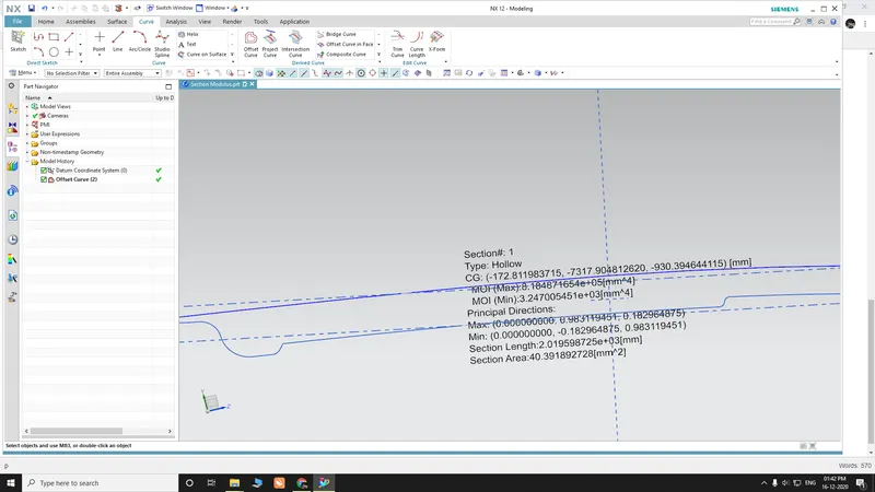
Info Analysis - Section Inertia Analysis


The mass properties are for hollow sections

Sect#  CG-XC     CG-YC     CG-ZC     CG-X      CG-Y      CG-Z      SL        SA
1      -172.811983715 -7317.904812620 -930.394644115 -172.811983715 -7317.904812620 -930.394644115 2.019598725e+03 40.391892728

Sect#  Max-MI    Max-X     Max-Y     Max-Z     Min-MI    Min-X     Min-Y     Min-Z     Max-RL    Min-RL
1      8.184871654e+05 0.000000000 0.983119451 0.182964875 3.247005451e+03 0.000000000 -0.182964875 0.983119451 479.382351161 18.286
969082

Sect#: Number of Section

CG-XC, CG-YC, CG-ZC: Center of Gravity (WCS) [mm]
CG-X, CG-Y, CG-Z: Center of Gravity (Absolute) [mm]

Max-MI: Maximum Principal Moments of Inertia [mm^4]
Max-X, Max-Y, Max-Z: Maximum principal Direction

Min-MI: Minimum Principal Moments of Inertia [mm^4]
Min-X, Min-Y, Min-Z: Minimum principal Direction

Max-RL: Equivalent rectangle section length in Max principal direction [mm]
Min-RL: Equivalent rectangle section length in Min principal direction [mm]

SL: Section Length [mm]
SA: Section Area [mm^2]

From the above analysis, following minimum and maximum moment of inertia are obtained
Imax =8.18e+05 mm4
Imin =3.247e+03 mm4
y" for section of hood design 2 = 242 mm


Smax = Imax / y=8.18e+05/242    =3382.17mm3………………….. (03)
Smin = Imin /y=3.247e+03/242    =13.417mm3………………….. (04)
Conclusion:
- By comparing the values (001) and (03) we can say that section modulus of the optimized hood (design 2) is increased by 0.5% .
- Section modulus for the previously designed hood (design 1) and optimized hood (design 2) are calculated.
- Section modulus for the previously designed hood (design 1) is optimized to increase the section modulus there by increasing the resistance against bending stress.