Section Modulus calculation and optimization
Report On Hood Section Modulus
Aim
The aim of this study is to calculate the section modulus of the hood to analyze its resistance to bending and also to provide an optimization analysis to measure the difference in the section modulus when the hood depth is modified by 0.5mm.
Section modulus
According to Wikipedia (https://en.wikipedia.org/wiki/Section_modulus), “the Section modulus is a geometric property for a given cross-section used in the design of beams or flexural members. Other geometric properties used in design include area for tension and shear, radius of gyration for compression, and moment of inertia and polar moment of inertia for stiffness. Any relationship between these properties is highly dependent on the shape in question. Equations for the section moduli of common shapes are given below”:




Fig 1 – Area Moments of Inertia for Various Shapes (Source: Wikipedia)
Specifically, the Section Modulus is the ratio of the Second Moment of Area and the distance from the neutral axis to the extreme end of the member. It is calculated as follows:
S=I/Y
- S = Section modulus (mm3)
- I= Moment of Inertia (mm4)
- Y= Distance from Neutral axis to outer edge of object under study (mm)
From Wikipedia (https://en.wikipedia.org/wiki/Second_moment_of_area), “The second moment of area, or second area moment, or quadratic moment of area and also known as the area moment of inertia, is a geometrical property of an area which reflects how its points are distributed with regard to an arbitrary axis.
In structural engineering, the second moment of area of a beam is an important property used in the calculation of the beam's deflection and the calculation of stress caused by a moment applied to the beam. In order to maximize the second moment of area, a large fraction of the cross-sectional area of an I-beam is located at the maximum possible distance from the centroid of the I-beam's cross-section. The planar second moment of area provides insight into a beam's resistance to bending due to an applied moment, force, or distributed load perpendicular to its neutral axis, as a function of its shape. The polar second moment of area provides insight into a beam's resistance to torsional deflection, due to an applied moment parallel to its cross-section, as a function of its shape.”
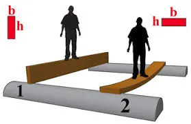
Fig 2 – Moments of Inertia about Different Axes
Intuitively, the “thicker” the material along the neutral axis (or axis of bending), the more rigid the structure will be. This makes sense as there will be more material to resist a load along the axis. The Area Moment of Inertia provides a description of the “thickness” of the material along the neutral axis, and as defined is a distance weighted summation of the area distribution around the axis.
MOI Study for Rectangle (Example)
Below, is a study we performed to calculate the MOI for a series of rectangles, with width of 250mm, and height starting at 120mm and increasing in increments of 40mm
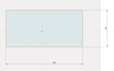
Fig 3a – Beginning Rectangle
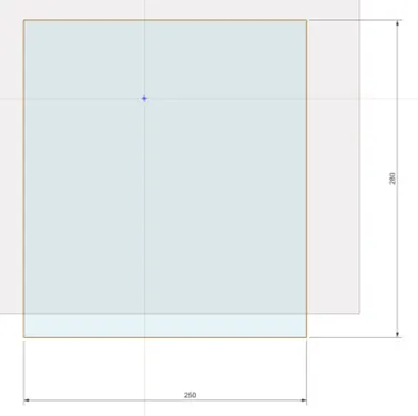
Fig 3b – Ending Rectangle
MOI Values for Various Rectangle Sizes
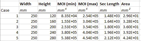
Fig 3c – MOI values as Rectangle Height Increases
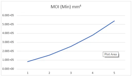
Fig 3d – Exponential relationship along width axis
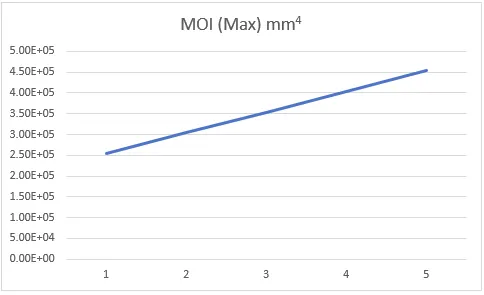
Fig 3e – Linear relationship along height axis
Above, we can see that MOI (Min) grows exponentially (to the 3rd power) taken along an access parallel to the width axis, while MOI (Max) grows linearly taken parallel to the height axis, as the equations predict.
First Design Study
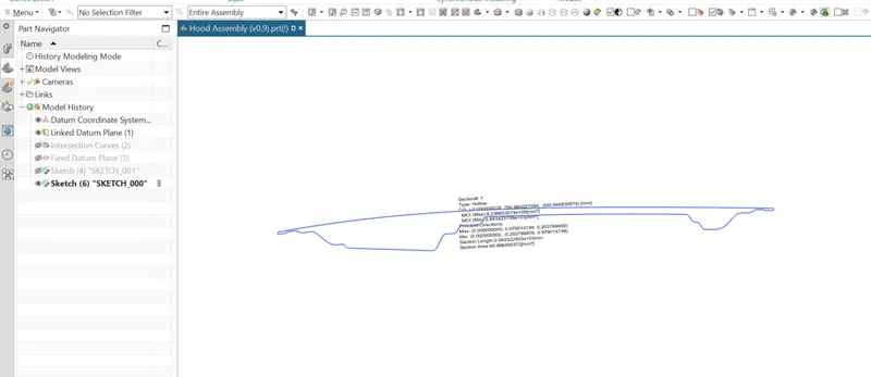
We took an Intersection Curve along the middle of the hood, and then projected the Curve into a Sketch. We then performed a Section Inertia Analysis on the Sketch.
Base Case
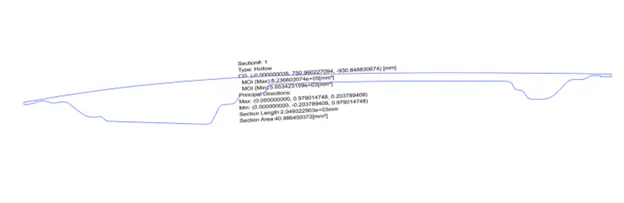
Fig 4a – Base Case
- Moment of inertia (max) = 8.2366×105 mm4
- Moment of inertia (min) = 5.6534×103 mm4 (along the “long” or “thin” axis)
- Y=487.97/2= 243.99mm
- S=I/Y
- S=5.6534×10³/243.99= 17 mm3
Optimization Case
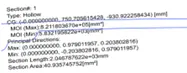
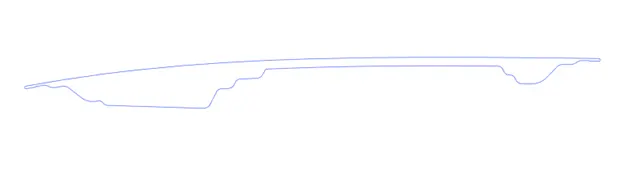
Fig 4b – Optimization Case
In the optimization case, we increased the depth of the inner panel by 0.5 mm
- Moment of inertia (max) = 8.2118×105 mm4
- Moment of inertia (min) = 5.8322×103 mm4 (along the “long” or “thin” axis)
- Y=487.97/2=243.99 mm
- S=I/Y
- S=5.8322×10³/243.99=90mm3
Conclusion
By increasing the depth of the hood by 0.5mm, we were able to increase the Section Modulus by 0.73mm3, making the hood stiffer and more resistant to bending along the axis in question.
Feature Tree