Section Modulus calculation and optimization
SECTION MODULUS AND OPTIMIZATION OF HOOD
AIM- Calculation of section modulus of hood and optimization to improve the overall section modulus.
The main objective of this project is to learn the basic tools, commands, and the calculation and optimization of hood using siemens NX CAD.
INTRODUCTION-
SECTION MODULUS- Section Modulus is named as the Extent of second preview of the area and distance between neutral axis to as far as fiber. Similarly, it is the Extent of the strength of the given part. The pressing factor in the fringe section of the column is figured with the help of the section modulus. It is appeared by S.
The "section modulus " is a numerical value that is determined by the cross-sectional shape of the part. In that sense, it is similar to "moment of inertia of area ". A "section modulus is the value of the "moment of inertia of area" related to the neutral axis of the cross-section of a beam multiplied by the distance from the neutral axis to the outer surface".
There are two types of section modulus-
- Elastic section modulus:
For general design, the elastic section modulus is used, applying up to the yield point for most metals and other common materials.
The elastic section modulus is defined as S = I / y, where I is the Second moment of inertia (or area moment of inertia, not to be confused with moment of inertia) and y is the distance from the neutral axis to any given fiber. It is often reported using y = c, where c is the distance from the neutral axis to the most extreme fiber, as seen in the table below. It is also often used to determine the yield moment (My) such that My = S ⋅ σy, where σy is the Yield Strength of the material.
- Plastic Section Modulus:
The plastic section modulus is used for materials where elastic yielding is acceptable and plastic behavior is assumed to be an acceptable limit. Designs generally strive to ultimately remain below the plastic limit to avoid permanent deformations, often comparing the plastic capacity against amplified forces or stresses.
The plastic section modulus depends on the location of the plastic neutral axis (PNA). The PNA is defined as the axis that splits the cross section such that the compression force from the area in compression equals the tension force from the area in tension. So, for sections with constant yielding stress, the area above and below the PNA will be equal, but for composite sections, this is necessarily the case. The Plastic Section Modulus is not the 'First moment of area'. Both relate to the calculation of the centroid, but Plastic Section Modulus is the Sum of all areas on both sides of PNA (Plastic Neutral Axis) and multiplied with the distances from the centroid of the corresponding areas to the centroid of the cross section, while the First moment of area is calculated based on either side of the "considering point" of the cross section and it is different along the cross section and depends on the point of consideration. The plastic section modulus is used to calculate the plastic moment, Mp, or full capacity of a cross-section. The two terms are related by the yield strength of the material in question, Fy, by Mp = Fy ⋅ Z. Plastic section modulus and elastic section modulus are related by a shape factor which can be denoted by k, used for an indication of capacity beyond elastic limit of material. This could be shown mathematically with the formula: K=Z/S
signification of section modulus: -
- Section modulus is the important factor for design of a bar and flexural part.
- The higher the worth of section modulus, the higher will be part to resistance of part to bending
- It is expected to calculate the stress of the beam.
- It is used to calculate the strength of the steel structure.
- More the section modulus can withstand more load.
Second moment of inertia-
The Second Moment of Area I is needed for calculating bending stress. It is the special "area" used in calculating stress in a beam cross-section during BENDING. Also called "Moment of Inertia".
It is directly related to the area of material of the cross section and the displacement of that area from the centroid. Once the centroided is located the more important structural properties of the shape can be calculated. The axis that determines the centroid is known as the neutral axis(N/A).
The second moment of area is a measure of the 'efficiency' of a shape to resist bending caused by loading. A beam tends to change its shape when loaded. The second moment of area is a measure of a shape's resistance to change.
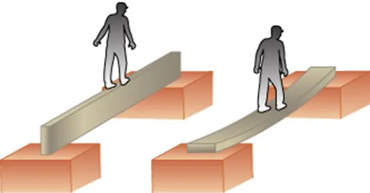
This picture contains the following scene. Diagram of a beam on its narrow edge supported at both ends. A man is walking on a straight beam. Diagram of a beam resting on its flat side supported at both ends. A man is walking on the straight beam and it is bending in the middle. - Certain shapes are better than others at resisting bending as demonstrated in the diagram. Clearly, the orientation of the shape also influences bending. - In its simplest way, the more the section modulus is more the material is resistant to the deformation.
To study how the value of section modulus changes when there is a change in surface area, the following steps are mentioned while using NX CAD software. We use Elastic Section Modulus for section modulus calculation and optimization of hood.
CASE 1 BEFORE OPTIMIZATION: -
The hood was already created is imported and the section inertia Analysis is done.
We have to make sure that the curve obtained is of a single / Closed curve.
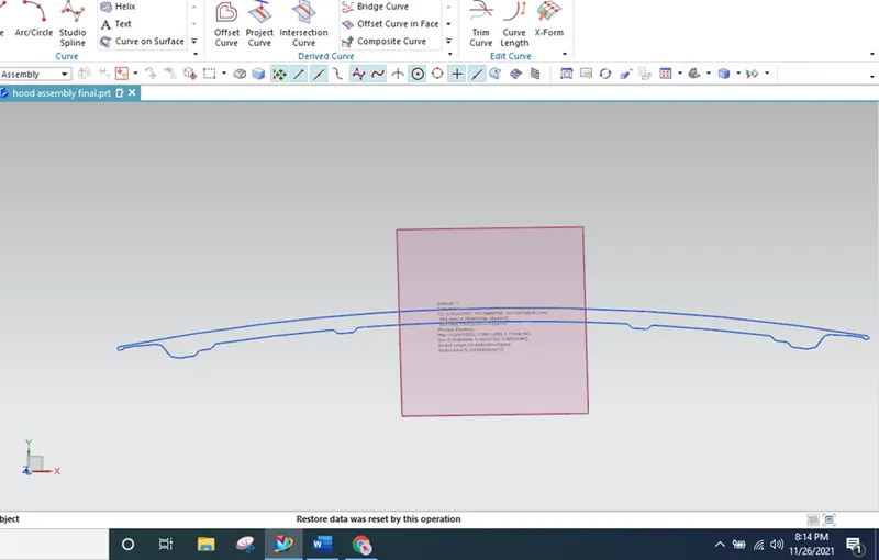
Go to Analysis> Section inertia analysis> select curve
The Moment of Inertia (MOI) obtained from this analysis is as shown below
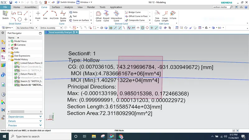
From the above analysis, following minimum and maximum moment of the inertia are obtained, using MOI (min)
Calculation of section modulus of main hood
Moment of Inertia (MOI), Imax = 4.783666167x 10^6 [mm^4]
Moment of Inertia (MOI), Imin = 1.402971322x 10^4 [mm^4]
Distance between the neutral axis and the extreme end of the object, y = 880.14mm / 2 = 440.07 mm
Section Modulus S=Moment of Inertia (MOI), I / Distance between the neutral axis and the extreme end of the object (y) S=I/Y
For Minimum (MOI),
S= (1.4029 X 10^4) / 440.07
=31.87mm^3
Case 2 - Hood Optimized Design
Section modulus analysis for case 2
By offsetting the inner panel by 0.5 mm and then closed curve as like case 1 .
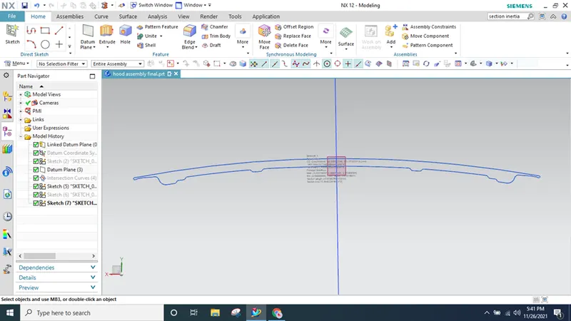
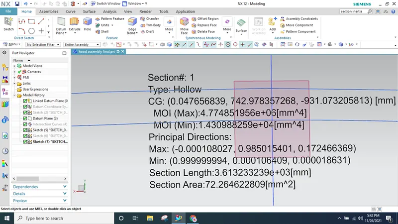
Calculation of section modulus of optimized hood
Moment of Inertia (MOI), Imax = 4.774851956x 10^6 [mm^4]
Moment of Inertia (MOI), Imin = 1.430988259x 10^4 [mm^4]
Distance between the neutral axis and the extreme end of the object, y = 880.14mm / 2 = 440.07 mm
Section Modulus S=Moment of Inertia (MOI), I / Distance between the neutral axis and the extreme end of the object (y) S=I/Y
For Minimum (MOI),
S= (1.4309 X 10^4) / 440.07
=32.51mm^3
When compared section values in case 1 and case 2, when increase in cross sectional area there will be increase in minimum strength or maximum strength.
Conclusion:
Hence when comparing case 1 & case 2 calculation
- The section modulus value of case 2 is higher than the case 1.
- As we increase the section area, the moment of inertia & section modulus increases which means strength and load material also increase.
3.The strength of the material is directly proportional to the moment of inertia, hence increase in sectional area there is have increase in overall mass of an object, hence have increase in strength.