Section Modulus calculation and optimization
Objective
To calculate Section Modulus of the Hood and Optimize the design to improve the Section Modulus.
Section Modulus:
The Section Modulus is a geometric property used in the design of flexural members. It directly measures the strength of a cross-sectional area. Mathematically, it can be defined as the ratio of total moment resisted by the section to the stress in the extreme fibre which is equal to yield stress.
s = I / y
Where,
s=Section modulus
I= Moment of Inertia of the section to the stress in the extreme end of the object (mm^4)
y= Distance between the neutral axis and the extreme end of the object (mm)
For general Design, the elastic section modulus is used, applying up to the yield point for most metals and other common materials.
Neutral Axis:
The Neutral Axis is an imaginary line where no longitudinal stress either compressive or tensile stress or no strain exists. The neutral axis is represented by a dotted line.
From the neutral axis, the upper part in a beam is under compressive stress and the lower part of the neutral axis is under tensile stress. Hence the moment of area of any structure with respect to the neutral axis is always zero due to this from the neutral axis for a beam subjected to the same simple bending moment.
Moment of Inertia (MOI):
The Moment of Inertia is defined as the quantity expressed by the body revisiting angular acceleration which is the sum of the product od the mass of every particle with square of the distance from the axis of rotation. In simple words, it is the quantity that decides the amount of torque needed for a specific angular acceleration. It can also be known as Rotational Inertia and its SI unit is [Kgm^2].
In General form,
Moment of Inertia (I) = m*r^2
where,
m = Sum of the product of the mass.
r = Distance from the axis of the rotation.
Calculation of Section Modulus for the Hood
Sectional view:

Figure 1 Section view
Data gathered using NX cad
The below screenshot is shown which consist the essential data for the calculation of the Section modulus like moment of inertia (maximum and minimum), Section length and section area.
Case 1
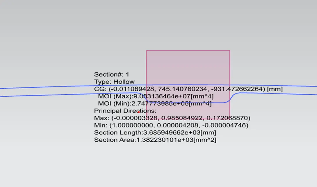
Figure 2 - Data of Case 1
Here,
Maximum Moment of Inertia I (Max) = 9.083136464e+07 [mm^4]
Minimum Moment of Inertia I (Min) = 2.747773985e+05 05[mm^4]
Total distance Y = 879.5792
Distance between the neutral axis and extreme end of object
y = [Total distance(Y) / 2]
y = 879.5792 / 2
y = 439.7896
Therefore,
Section Modulus s = I / y
s = (2.747773985e+05) / 439.7896
s = 624.5 mm^3
Optimized Hood design
Case 2
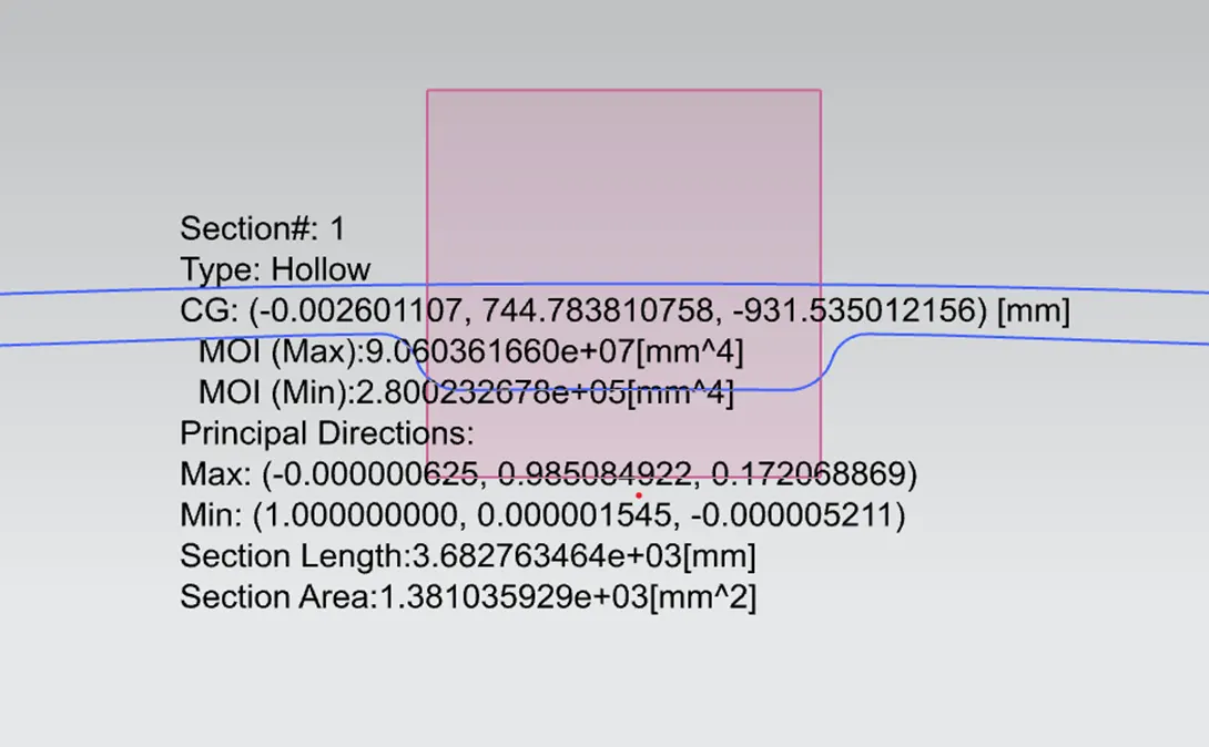
Figure 3 – Data of Case 2.
Here,
Maximum Moment of Inertia I (Max) = 9.06036160e+07 [mm^4]
Minimum Moment of Inertia I (Min) = 2.800232678e+05 [mm^4]
Total distance Y = 879.5792
Distance between the neutral axis and extreme end of object
y = [Total distance(Y) / 2]
y = 879.5792 / 2
y = 439.7896
Therefor,
Section Modulus s = I / y
s = 2.800232678 / 439.7896
s = 636.363 mm^3
Result:
The section modulus for the Hood in first design is 624.5 mm^3 and when the design is changed then the optimized section modulus is 636.363 mm^3. So by comparing the both section modulus the optimized design get higher value that means it get more strength then the first design because the section modulus is used to check the strength of the design.
Conclusion:
As per the above work we conclude that as the section area of the design changes the moment of inertia changes and the section modulus also changes. That means the strength of the design get improve das the section modulus increased.