Section Modulus calculation and optimization
Objective:
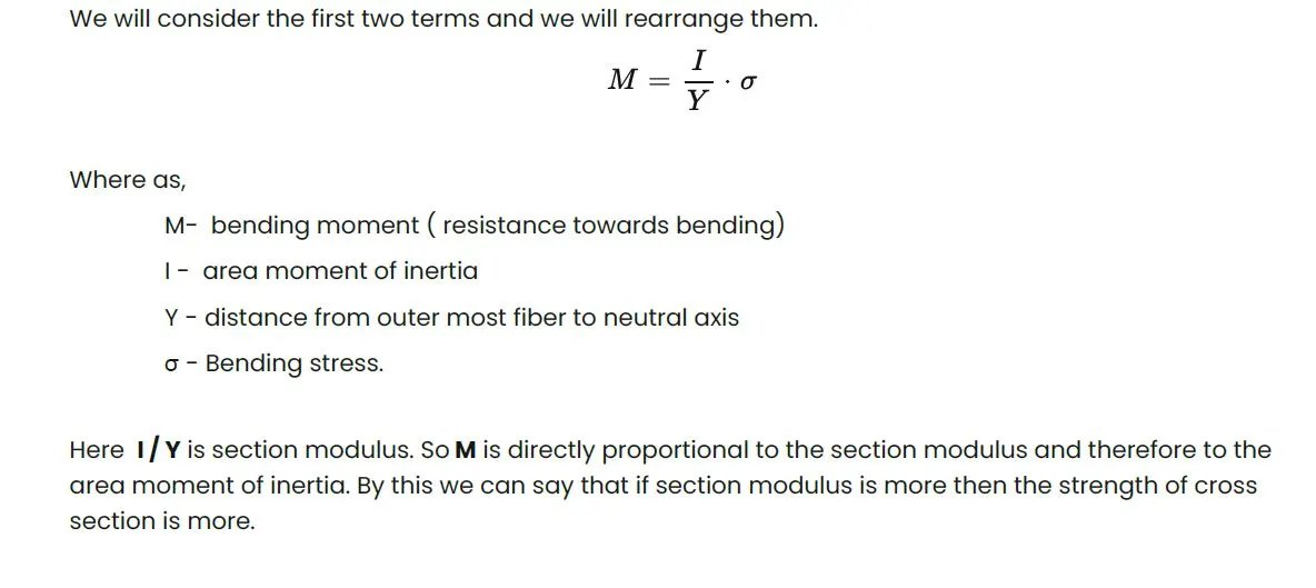
The main objective is this challenge is to calculate the section modulus for we designed the hood in the previous challenge by using the formula
S = I/y
Where,
S = Section Modulus
I = Moment of Inertia
y = distance between the neutral axis and the extreme end of the object
Section Modulus:
It is the ratio of area moment of inertia about the neutral axis and to the distance ofoutermost fiber from the neutral axis.
Z =I / Y [ units: mm3 or m3 ]
Where as,
Z = Section Modulus
I = Area moment of inertia
Y = Distance from neutral axis to the outermost fiber
Area moment of inertia:
Area moment of inertia will depict the resistance offered by the body towardsbending due to its cross section.
Neutral Axis:
The line in a beam or other member subjected to a bending action in which the fibers areneither stretched nor compressed or where the longitudinal stress is zero.
Section modulus is a geometric property for a given cross-section used in the design of beams or flexural members. Other geometric properties used in design include area for tension and shear, radius of gyration for compression, and second moment of area and polar second moment of area for stiffness. Any relationship between these properties is highly dependent on the shape in question. Equations for the section moduli of common shapes are given below. There are two types of section moduli, the elastic section modulus and the plastic section modulus.
Elastic Section Modulus:
For general design, the elastic section modulus is used, applicable up to the yield point for most metals and other common materials.
The elastic section modulus is defined as S = I / y, where I is the second moment of area (or area moment of inertia, not to be confused with moment of inertia) and y is the distance from the neutral axis to any given fibre. It is often reported using y = c, where c is the distance from the neutral axis to the most extreme fibre, as seen in the table below. It is also often used to determine the yield moment (My) such that My = S ⋅ σy, where σy is the yield strength of the material.
| Cross-sectional shape | Figure | Equation | Comment |
|---|---|---|---|
| Rectangle |  |
Solid arrow represents neutral axis | |
| doubly symmetric I-section (major axis) | 
|
NA indicates neutral axis | |
| doubly symmetric I-section (minor axis) |  [4] [4] |
NA indicates neutral axis | |
| Circle |  [3] [3] |
Solid arrow represents neutral axis | |
| Circular hollow section |  |
Solid arrow represents neutral axis | |
| Rectangular hollow section |  |
NA indicates neutral axis | |
| Diamond |  |
NA indicates neutral axis | |
| C-channel | |
NA indicates neutral axis |
 ,
,
Plastic Section Modulus:
The plastic section modulus is used for materials where elastic yielding is acceptable and plastic behavior is assumed to be an acceptable limit. Designs generally strive to ultimately remain below the plastic limit to avoid permanent deformations, often comparing the plastic capacity against amplified forces or stresses.
The plastic section modulus depends on the location of the plastic neutral axis (PNA).The PNA is defined as the axis that splits the cross section such that the compression force from the area in compression equals the tension force from the area in tension. So, for sections with constant, and equal compressive and tensile yielding stress, the area above and below the PNA will be equal, but for composite sections, this is not necessarily the case.
The plastic section modulus is the sum of the areas of the cross section on each side of the PNA (which may or may not be equal) multiplied by the distance from the local centroids of the two areas to the PNA:

The Plastic Section Modulus is not the 'First moment of area'. Both relate to the calculation of the centroid, but Plastic Section Modulus is the Sum of all areas on both sides of PNA (Plastic Neutral Axis) and multiplied with the distances from the centroid of the corresponding areas to the centroid of the cross section, while the First moment of area is calculated based on either side of the "considering point" of the cross section and it is different along the cross section and depends on the point of consideration.
| Description | Figure | Equation | Comment |
|---|---|---|---|
| Rectangular section |  [5][6] [5][6] |
 , , |
|
| Rectangular hollow section |  |
where: b = width, h = height, t = wall thickness | |
| For the two flanges of an I-beam with the web excluded[7] |  |
where:
|
|
| For an I Beam including the web |  |
[8] | |
| For an I Beam (weak axis) |  |
d = full height of the I beam | |
| Solid Circle |  |
||
| Circular hollow section |  |
 =width,
 =thickness,
  are the distances from the neutral axis to the centroids of the flanges respectively.
The plastic section modulus is used to calculate the plastic moment, Mp, or full capacity of a cross-section. The two terms are related by the yield strength of the material in question, Fy, by Mp = Fy ⋅ Z. Plastic section modulus and elastic section modulus are related by a shape factor which can be denoted by k, used for an indication of capacity beyond elastic limit of material. This could be shown mathematically with the formula :-

Shape factor for a rectangular section is 1.5.
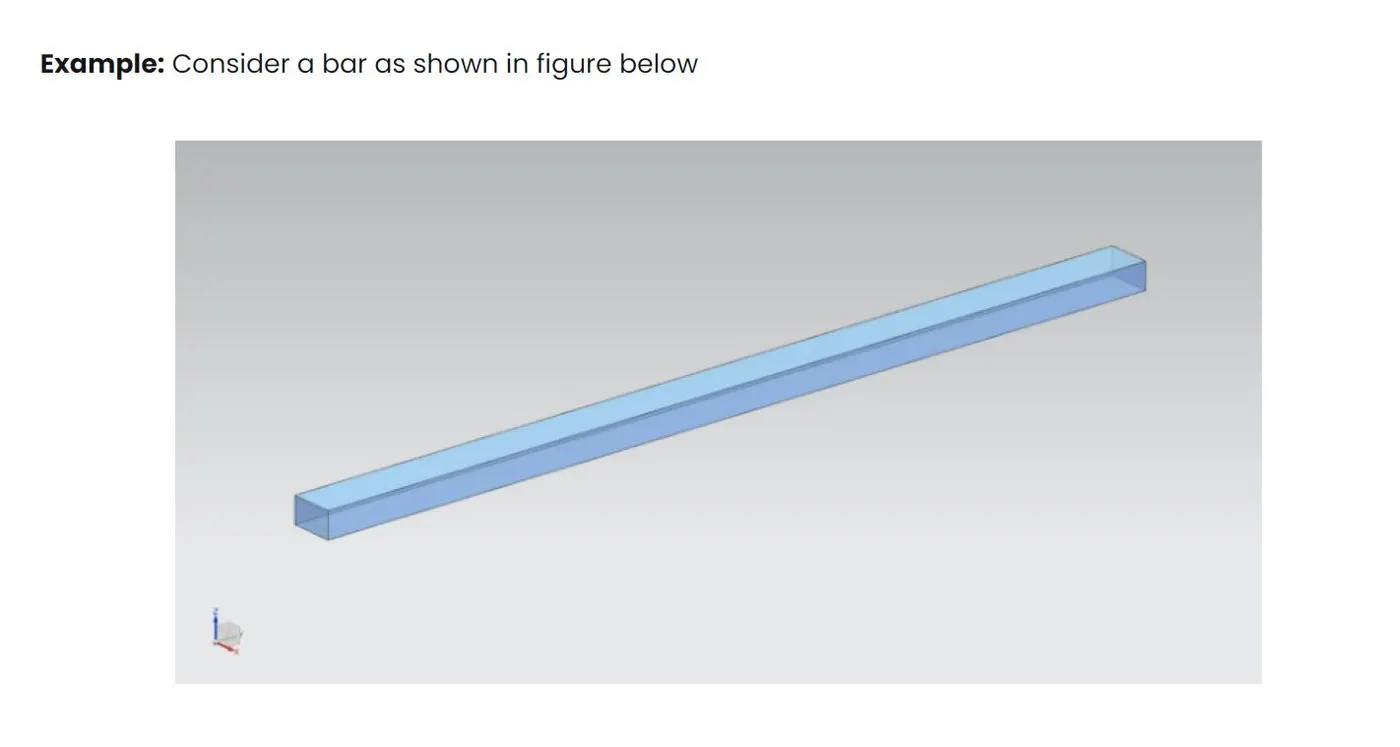
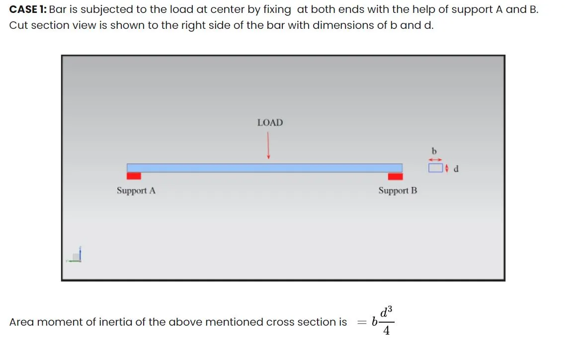
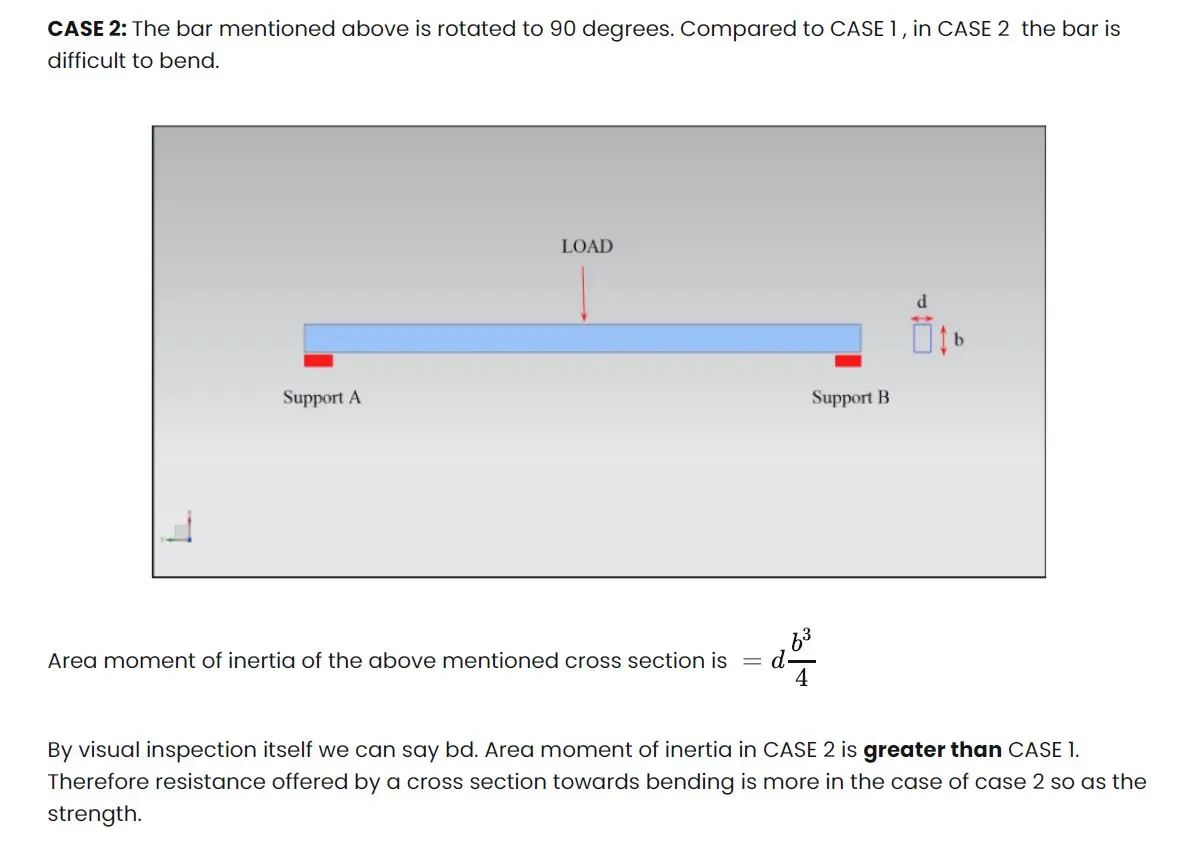
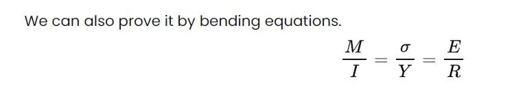
In this challenge we are using the Elastic Section Modulus, which was calculated by using the bending equation method,
Section Modulus for our Hood Design:
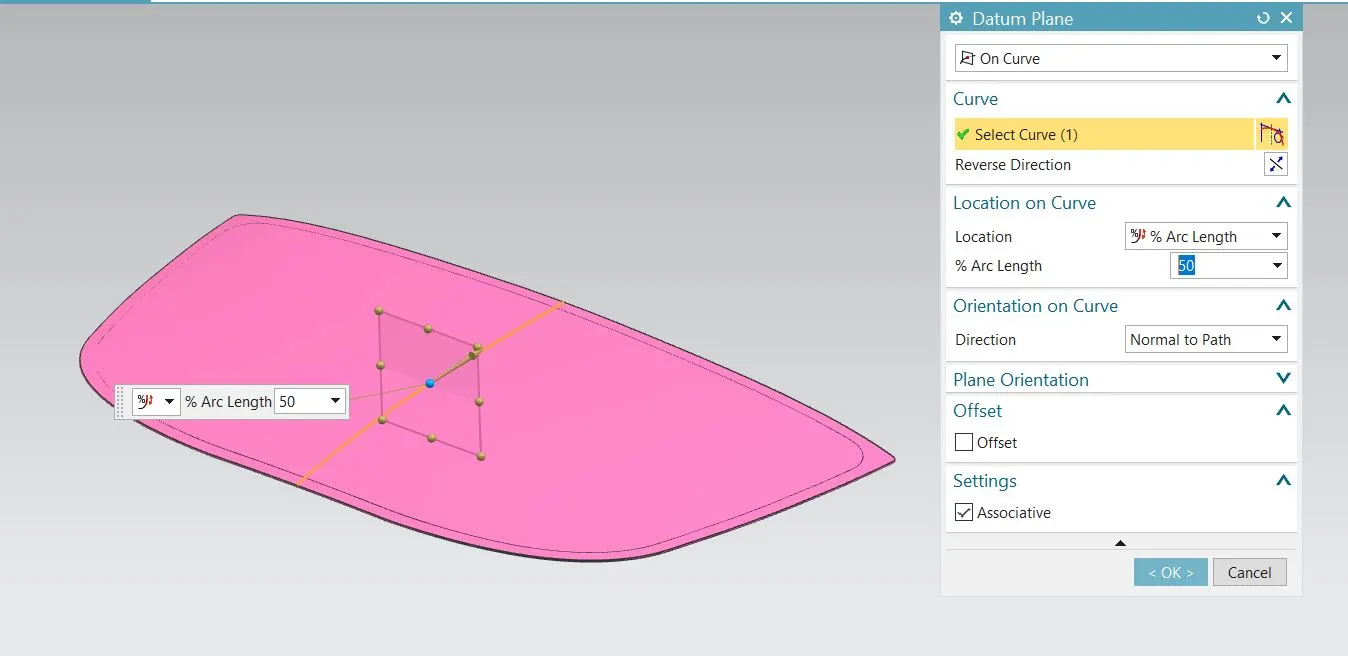
Create a datum plane on the centre of the hood using the on curve option and provide % arc length as 50% , So that we getexactly at the center of the hood.
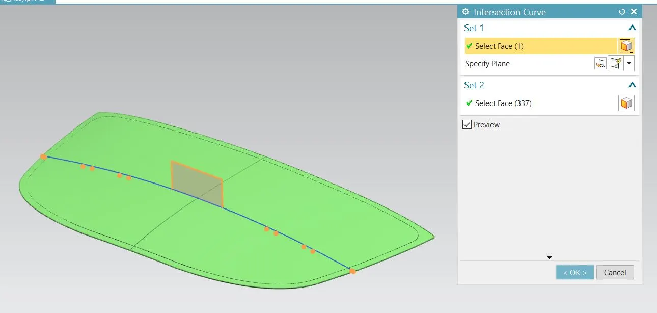
After we want intersection on the middle of the solid body by using the datum plane which was created right now. in that option one face is taken as datum plane and another one is taken as the solid body by using the tangent curve option.
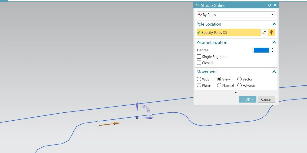
Hide all the solid bodies and create a sketch on the datum plane we have created. Then use the intersection curve to project on this sketch. After check the sketch if any gap is there we want to close the sketch by using the studio spline Select the option of ‘by poles’ and tick ‘single segment’. Select the starting point and ending point atthat specific gap to close the open sketch.
After select the section inertia analysis, in that use this closed curve sketch and provide the thickness as 0.75mm, and We will get a result as shown in the image below. Take the minimum MOI into consideration forcalculating the section modulus.
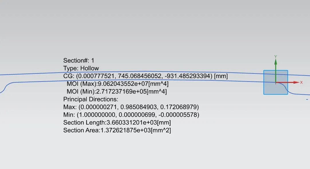
Then we want the Y value, for getting this value we measure the distance between the end to end of the section then divided by 2 be the answer of the Y value.
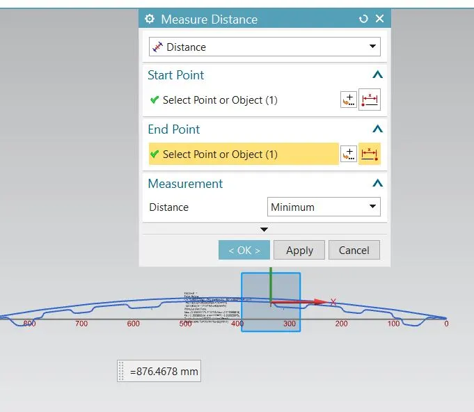
Y = 876.4678 / 2 = 438.2339
From the above section calculation we are getting, Moment of inertia (max) I = 9.062043552 * e^7 (mm^4)
Moment of Inertia (min) I = 2.717237169 * e^5 (mm^4)
For max ;
Section Modulus (Z) max = I / Y
= (9.062043552 * e^7) / 438.2339
= 22.6767 mm^3
For min ;
Section Modulus (Z) min = (2.717237169 * e^5) / 438.2339
= 0.9202 mm^3
Here strength of the hood is ranges from 0.9202 to 22.6767 mm^3
After I decided to take one checking on this solid body by giving the inner panel depth to be increase then see the another calculated by the NX software and how the strength will impact while changing the depth of the inner panel arrangement.
In this I'm using the same sketch which was created will project the new sketch. In this sketch I'm just offset the inner panel intersection curve for 0.5 mm distance and then closed the profile curve by using the studio spline option. After I'm giving the section inertia analysis for this to find the new inertia value.
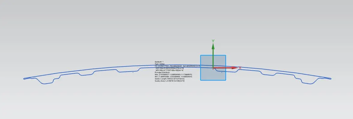
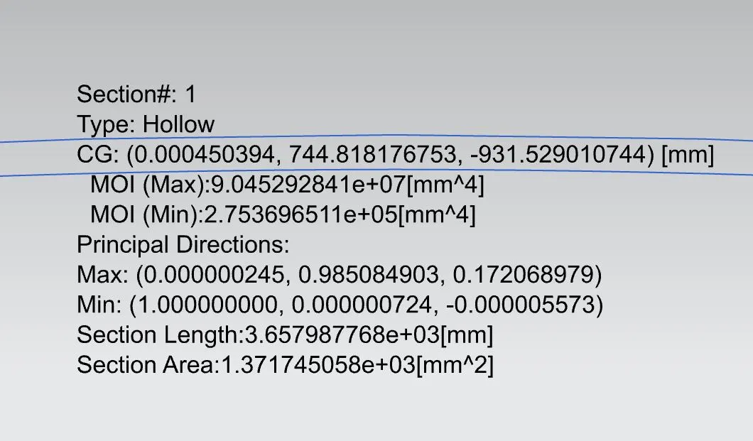
From the above section calculation we are getting, Moment of inertia (max) I = 9.045292841 * e^7 (mm^4)
Moment of Inertia (min) I = 2.753696511 * e^5 (mm^4)
For max ;
Section Modulus (Z) max = I / Y
= (9.045292841 * e^7) / 438.2339
= 22.6348716 mm^3
For min ;
Section Modulus (Z) min = (2.753696511 * e^5) / 438.2339
= 0.93257 mm^3
Here strength of the hood is ranges from 0.93257 to 22.6348 mm^3
Then comparing the both changed cross sectional areas section modulus calculation we came to know that, increase in cross sectional area results in increase in strength. But in the maximumum inertia range is decreased while increasing the inner panel depth.
Finally we know that the strength of the material is directly proportional to the moment of inertia, hence increase in sectional area there is have increase in overall mass of an object ,hence have increase in strength.