Section Modulus calculation and optimization
Section Modulus & Optimization
Objective:
The main objective is to calculate section modulus & moment of inertia of the hood which we designed and changing necessary data to improve the rigidity of hood using siemens Nx application.
Introduction:
Section modulus is a geometric property for a given cross-section used in the design of beams or flexural members. Other geometric properties used in design include area for tension and shear, radius of gyration for compression, and moment of inertia and polar moment of inertia for stiffness.
Design Methodology:
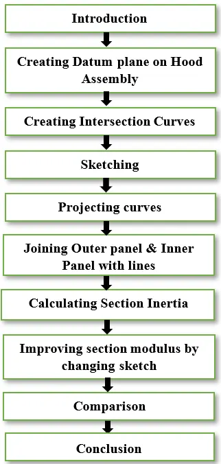
The Steps involved in calculating section modulus is explained through flow charts.
Description:
Introduction:
- Copying Hood Assembly file and creating new folder as Section Modulus. Then saving copied file in that folder.
- Starting Hood Assembly file in Siemens Nx application.
- Clicking on Assembly navigator, hide the hinge assembly and striker assembly.
Creating Datum Plane on Hood Assembly:
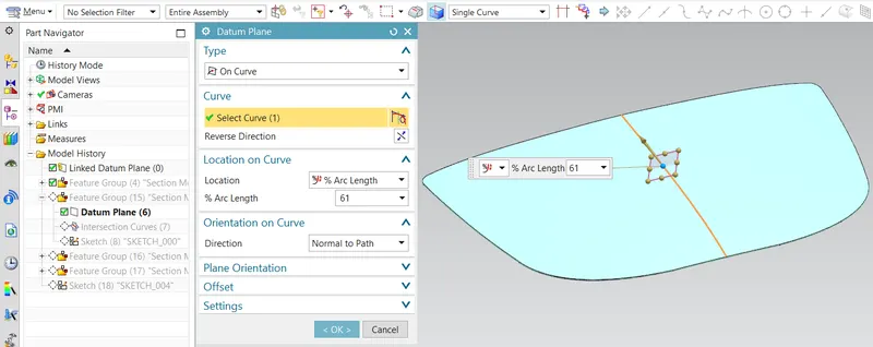
- Double clicking on hood assembly to create datum plane on hood.
- Clicking on datum plane tab the dialog box appears, in that select type as On Curve, select curve on hood before that (change to Entire assembly and Single curve on ribbon bar), select location as % Arc Length & 61%. Then click Ok to validate.
Creating Intersection Curves:
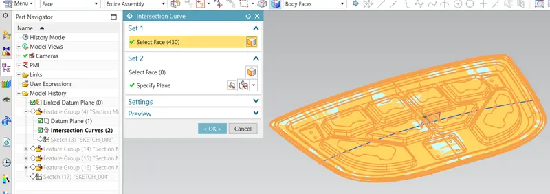
- Clicking on curve tab, select intersection curve icon the dialog box appears, in that select body faces of hood assembly (by changing single face to body faces on ribbon bar) and select datum plane. Then click ok to validate.
- Hide outer panel & inner panel in Assembly Navigator to see intersection curves clearly.
Sketching:
- Clicking on sketch on task environment icon in that selecting sketch plane as datum plane, specify vector as x axis, specify point on intersection curves and click ok to validate.
Projecting Curves:
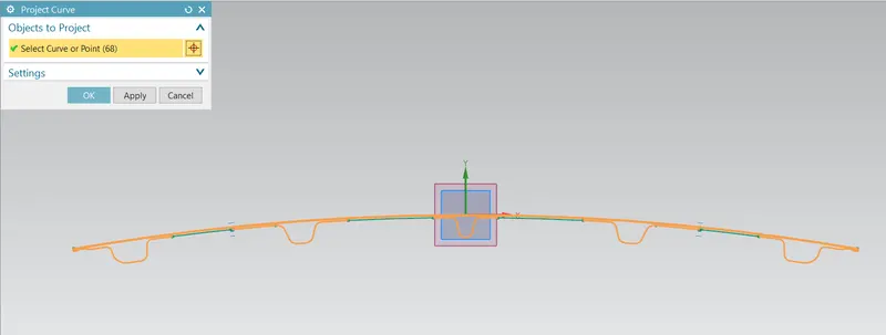
- Clicking Project curve icon in that select intersection curves and click ok to validate.
Joining Outer Panel & Inner Panel with Lines:
- Clicking on the make corner icon, this command used to join corners by clicking on lines.
- Adding studio splines command wherever necessary to join two points.
- Click G1 to join two points as tangent.
- And trim the sketch wherever necessary to finish the sketch.
Calculating Section Inertia:
- Click on menu icon select analysis and choose section inertia.
- Clicking on section inertia analysis icon the dialog box appears, in that select type as Existing section, selecting sketch curves, select type as hollow and add 0.75 mm as hollow thickness.
Improving Section modulus by changing sketch:
- Redoing the same process, but changing parameters to the sketch to improve moment of inertia.
Comparison:
- Original Hood Design:

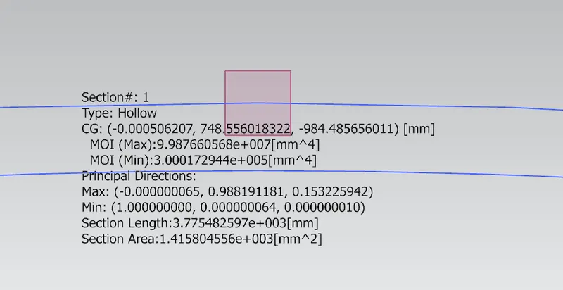
From the above image, the following data can be noted:
MOI (Max): 99876605 mm^4
MOI (Min): 300017 mm^4

y= 896/2 mm = 448 mm
Therefore, the maximum and minimum section modulus is calculated below:
Section Modulus S = I/y
S (Max) = 99876605/448 = 222938.85 mm^3
S (Min) = 300017/448 = 669.68 mm^3
2. Hood Design Changed:
Changes made to Original Hood Design:
- Moment of Inertia: It is defined as the product of mass of section and the square of the distance between the reference axis and the centroid of the section.
- So, the above statement the MOI will increase if the mass or the length of the body is increased.
- In order to increase the strength of the hood the minimum section should be high, as moment of inertia is directly proportional to section modulus, then the values of MOI should increase, to increase the MOI the cross-sectional area should be increased.
- The minimum moment of inertia indicates the minimum load the hood can withstander the start of the breaking point of the hood.
- From the above observation, to increase the cross section of the hood, the hood outer panel will be offset upwards direction by a value of 1 mm.
- By performing the above operation, again calculating the moment of inertia to the newly created sketch.

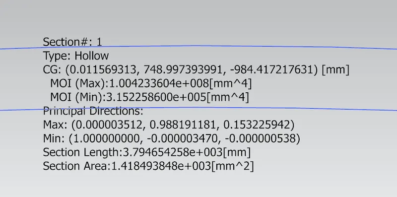
From the above image, the following data can be noted:
MOI (Max): 100423360 mm^4
MOI (Min): 315225 mm^4
y= 896/2 mm = 448 mm
Therefore, the maximum and minimum section modulus is calculated below:
Section Modulus S = I/y
S (Max) = 100423360/448 = 224159.28 mm^3
S (Min) = 315225/448 = 703.62 mm^3

Conclusion:
- By comparing the values of the minimum moment of inertia for the original design and the changed design, we can observe that the moment of inertia increases if the cross-sectional area of the hood increases.
- The changed hood will have higher strength, so it will be able to withstand more load when compared to original hood.
- Finally, we concluded the section modulus calculation and optimization using siemens Nx application.