Section Modulus calculation and optimization
SECTION MODULUS
It is a geometric characteristic applied to the design of beams or flexural members for a specific cross-section. Area for tension and shear, the radius of gyration for compression, moment of inertia, and polar moment of inertia for stiffness are some other geometric parameters employed in the design.
Basically, there are two types of section modulus:
- Elastic section modulus
- Plastic section modulus
For most metals and other common materials, up to the yield point, the elastic section modulus is utilized for the general design.
S = I / y is the formula for the elastic section modulus, where I is the second moment of area (also known as the area moment of inertia, not to be confused with the moment of inertia) and y is the separation between any two fibers from the neutral axis.
It is also frequently used to calculate the yield moment (My), where My = S y, where y is the material's yield strength and represents the maximum permissible load in a mechanical component.
For materials where elastic yielding is permitted and plastic behavior is assumed to be an acceptable limit, the plastic section modulus is utilized.
ROLE OF CROSS-SECTION IN SECTION MODULUS:
- Only the beam's cross-sectional form affects section modulus. such as composite sections, I sections, and T sections in addition to rectangular, square, and circular cross sections.
- The value of "section modulus" for symmetric sections is true for sections above and below the centroid of the fibre.
- Due to the different distances from the centroid to the top and bottom of the material, an asymmetric section has two values for the top and bottom of the fiber; the maximum "section modulus" is S max, and the minimum section modulus is S min.
STEPS FOLLOWED FOR CALCULATING SECTION MODULUS
I copied two parts from the Hood outer panel and inner panel into a new part model called Section modulus, created section geometry from the outermost geometry of the Hood outer panel and lowermost geometry of the Hood inner panel, and joined them with lines because we need a closed profile to measure the inertia. Finally, I carried out the calculation to determine the Allowable Moment of Inertia by using a command i.e Section Inertia Analysis.
Using the concept that section modulus (S) is directly proportional to the area moment of inertia (I) and taking y as unity we can calculate the section modulus.
CASE 1 : Section Modulus Calculated in Hood for Side Impact
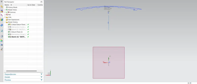
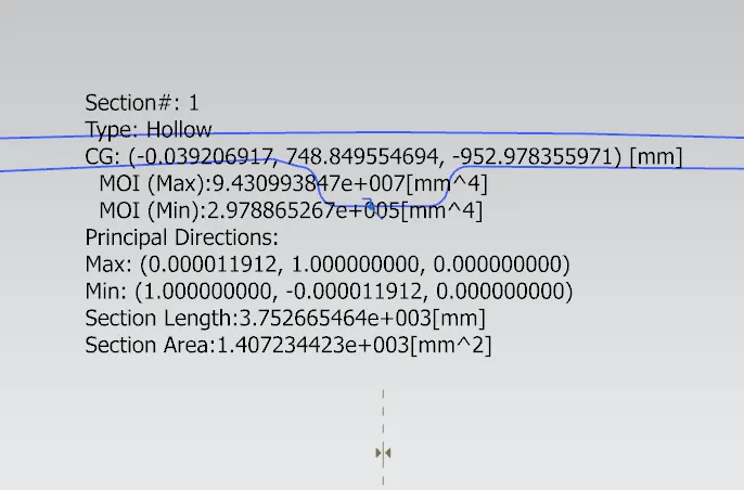
As we see above Min MOI (I) is 2.978865267e+005 mm^4 (and as S is directly proportional to I)
using, S= I/y
For unit Y distance, S= 2.978865267e+005 mm^3
OPTIMISATION
Offset inner pannel by 0.75mm Outward
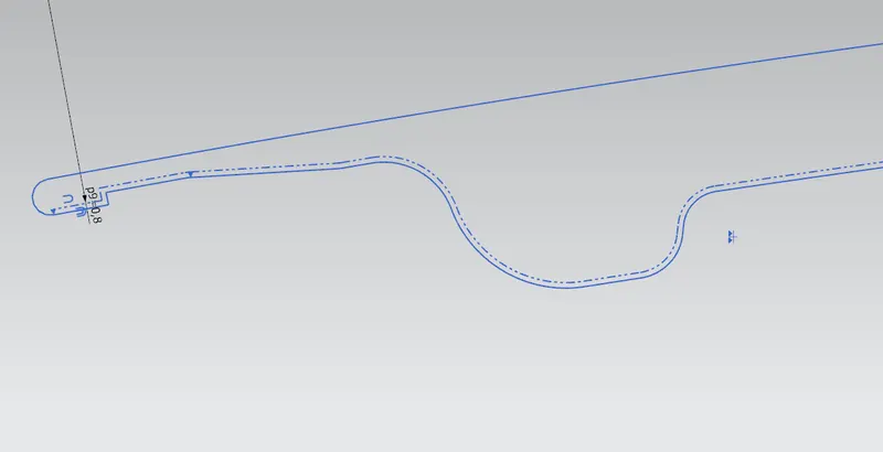
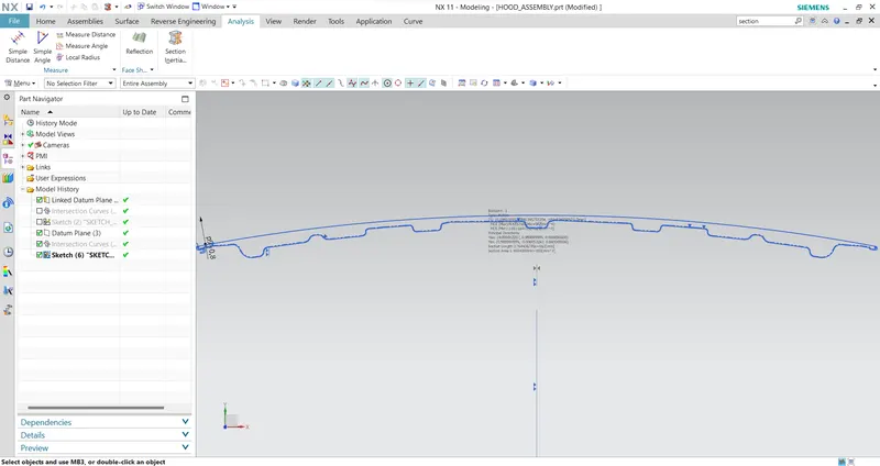
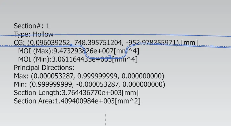
As we see above Min MOI is 3.061164435e+005 mm^4
For unit Y distance, S= 3.061164435e+005 mm^3
Offset inner pannel by 1mm Outward
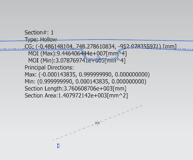
As we see above Min MOI is 3.07876974e+005 mm^4
For unit Y distance, S= 3.07876974e+005 mm^3
CONCLUSION-
Therefore, a small modification in the Sectional area results in a variation of the section modulus
between the initial and New hood is about 0.099904473e+005 mm^3
CASE 2: Section Modulus Calculated for Frontal impact
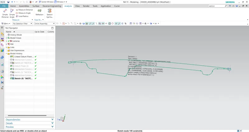
As we see above Min MOI (I) is 1.36455e+005 mm^4 (and as S is directly proportional to I)
using, S= I/y
For unit Y distance, S= 1.36455e+005 mm^3
OPTIMISATION
Offset inner pannel by 0.75mm Outward
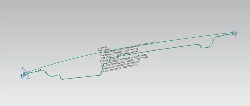
As we see above Min MOI is 1.431022925e+005 mm^4
For unit Y distance, S= 1.431022925e+005 mm^3
Offset inner pannel by 1mm Outward
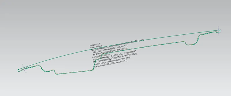
As we see above Min MOI is 1.453229624e+005 mm^4
For unit Y distance, S= 1.453229624e+005 mm^3
CONCLUSION
Therefore, a small modification in the Sectional area results in a variation of the section modulus
between the initial and New hood is about 0.088679624e+005 mm^3.
FINAL CONCLUSION FROM BOTH CASES
As a result, by extending the distance between the inner and outer panels of the hood assembly, we were able to obtain a larger value for the section modulus, which also increased the strength.