Section Modulus calculation and optimization
Section Modulus calculation and optimization
AIM-Calculate the section modulus of the previously constructed hood in order to analyse its strength and optimise the design in order to see the difference in bending strength. The greater a structure's section modulus, the more resistant it is to bending.
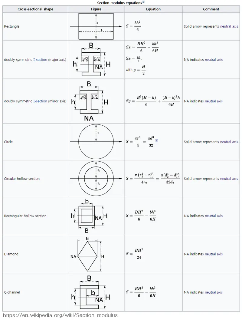
Section modulus is a geometric characteristic for a given cross-section that is utilised in beam or flexural member design. The area for tension and shear, the radius of gyration for compression, and the moment of inertia and polar moment of inertia for stiffness are also employed in the design. Any link between these attributes is heavily influenced by the form under consideration. The section moduli of common forms are provided as equations below. Section moduli are classified into two types: elastic section moduli and plastic section moduli. The section moduli of various profiles can also be obtained as numerical values for popular profiles in tables that detail their features.
Calculate the section modulus using the formula S = I/y and the Section from your Hood design.
S stands for Section Modulus.
I stands for Moment of Inertia.
y is the distance between the neutral axis and the object's extreme end.
Create a new section that improves on the prior section's section modulus and explain what changes you did to boost the strength.
ELASTIC SECTION MODULUS
For most metals and other common materials, the elastic section modulus is utilised for general design, up to the yield point.
S = I / y, where I is the second moment of area and y is the distance from the neutral axis to any particular fibre. As seen in the table below, it is commonly stated as y = c, where c is the distance from the neutral axis to the most extreme fibre. It is also frequently used to calculate the yield moment (My), such that My = S y, where y is the material's yield strength.
PLASTIC SECTION MODULUS
For materials where elastic yielding is permitted and plastic behaviour is regarded to be an acceptable limit, the plastic section modulus is utilised. To minimise irreversible deformations, designs often seek to stay below the plastic limit, sometimes evaluating the plastic capacity against amplified forces or stresses.
The placement of the plastic neutral axis affects the plastic section modulus (PNA). The PNA is defined as the axis that divides the cross section so that the compression force from the compressed area matches the tension force from the tension region. So, for sections with constant yielding stress, the area above and below the PNA will be equal, but this is not always the case for composite sections.
The plastic section modulus is the sum of the cross-sectional areas on either side of the PNA (which may or may not be equal) multiplied by the distance between the two regions' local centroids:

The Plastic Section Modulus is also known as the "First Moment of Area."
The plastic section modulus is used to compute a cross-plastic section's moment, Mp, or full capacity. Mp=Fy*Z is the relationship between the two terms and the yield strength of the material in question, Fy. Plastic section modulus and elastic section modulus are connected by a form factor represented by 'k,' which is used to indicate capacity beyond the elastic limit of the material. This might be demonstrated mathematically using the formula:

A rectangular segment has a form factor of 1.5.
So we're calculating the elastic section modulus.
Calculation:
CASE 1: Before Optimization
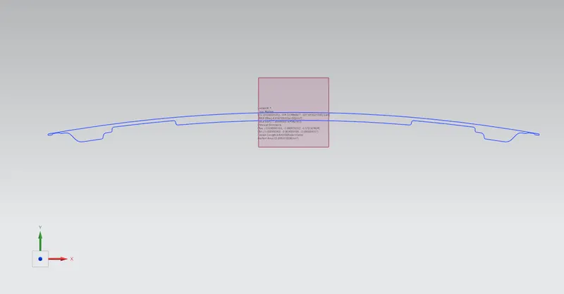
The Hood which was already created is imported and the section inertia analysis is done.
- we need to create the intersection between the hood and the internal panel.
- project the intersection on the datum plan.
- We have to make sure that the curve obtained is a single/closed curve for the we can use spline to connect all those remaining line .
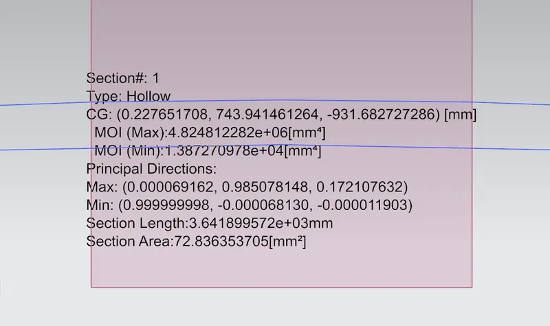
- Go the section modulus analysis select the face it will give analysis report
Calculation of Section Modulus of main Hood:
Moment of Inertia (MOI), Imax = 4.824812282 x 10^6 [mm^4]
Moment of Inertia (MOI), Imin = 1.38727098 x 10^4 [mm^4]
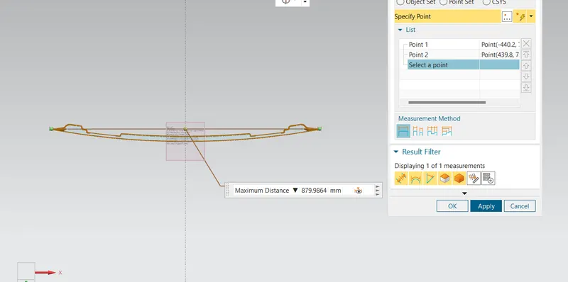
Distance between the neutral axis and the extreme end of the object, y = 879.986 mm / 2 = 439.993
Section Modulus, S = Moment of Inertia (MOI), I / Distance between the neutral axis and the extreme end of the
object (y)
For Maximum (MOI),
S = (4.824812282 x 10^6) / ( 439.993)
Smax = 10.96565x 10^3 mm^3
For Minimum (MOI),
S = (1.38727098 x 10^4 mm^4) / (439.993)
Smin = 0.0315293875x 10^3 mm^3
Hood Optimized Design
By creating the 2 mm offset of the inner panel in outer direction and joining the inner and outer panel lines the results are calculated.
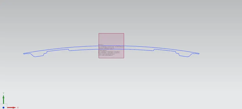
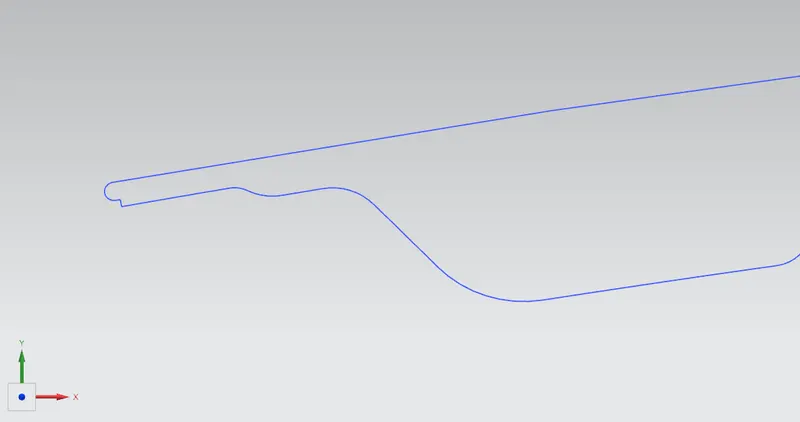
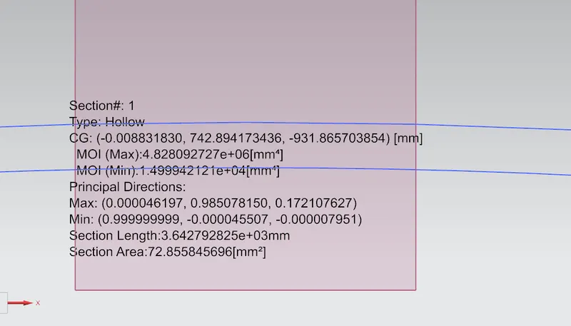
Moment of Inertia (MOI), Imax = 4.828092727x 10^6 [mm^4]
Moment of Inertia (MOI), Imin = 1.49994212 x 10^4 [mm^4]
Distance between the neutral axis and the extreme end of the object, y = 879.986 mm / 2 = 439.993
Section Modulus, S = Moment of Inertia (MOI), I / Distance between the neutral axis and the extreme end of the
object (y)
For Maximum (MOI),
S = (4.828092727x 10^6) / (439.993)
Smax = 10.97311258 x 10^3 mm^3
For Minimum (MOI),
S = (1.49994212 x 10^4 mm^4) / (439.993 )
Smin = 0.034090136 x 10^3 mm^3
Conclusion- So, here the difference can be seen in the moment of inertia and the change in the section modulus can be seen by the change in the depth.
with some changes or optimization and found some better results.