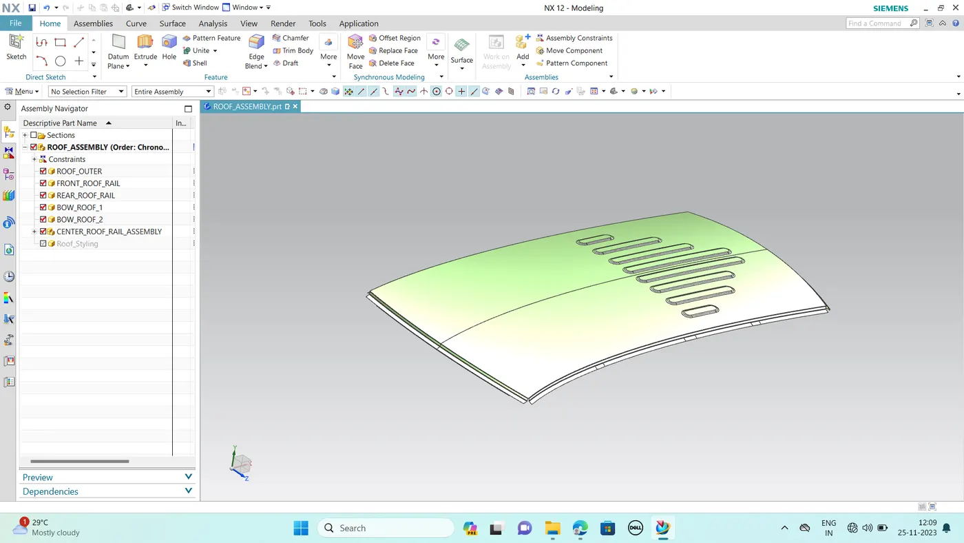
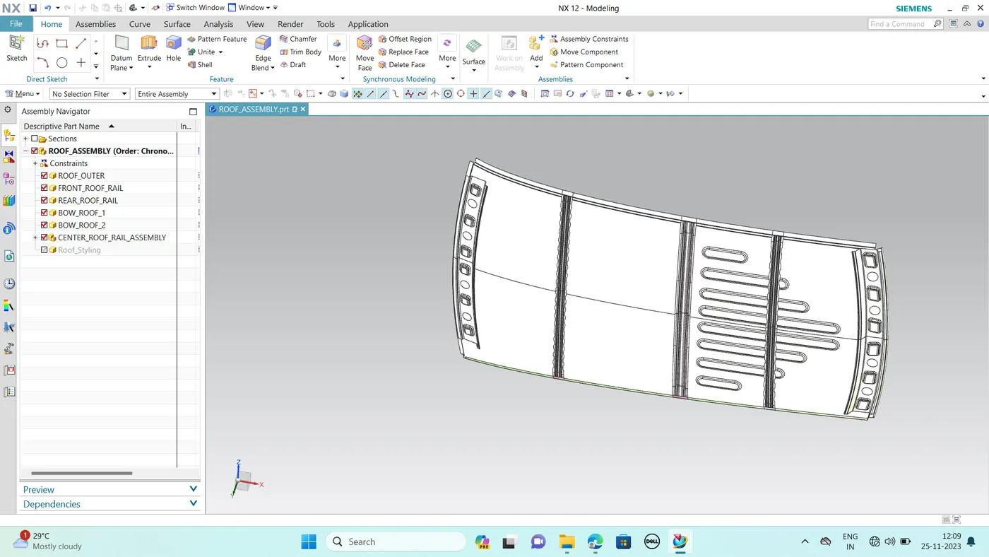
Roof Design
OBJECTIVE:
- Main objective of the project is to create the roof sheetmetal designin NX cad and also designing front roof rail, rear roof rail, bow roof front, bow roof rear, centre roof rail and reinforcement are creating to built strong roof.
- Do curvature study on roof and performance calculation for heat distortion and snow load criteria to determine the position of the bow roofs.
- Finding the moment of inertia and section modulus of bow roofa and centre roof rail.
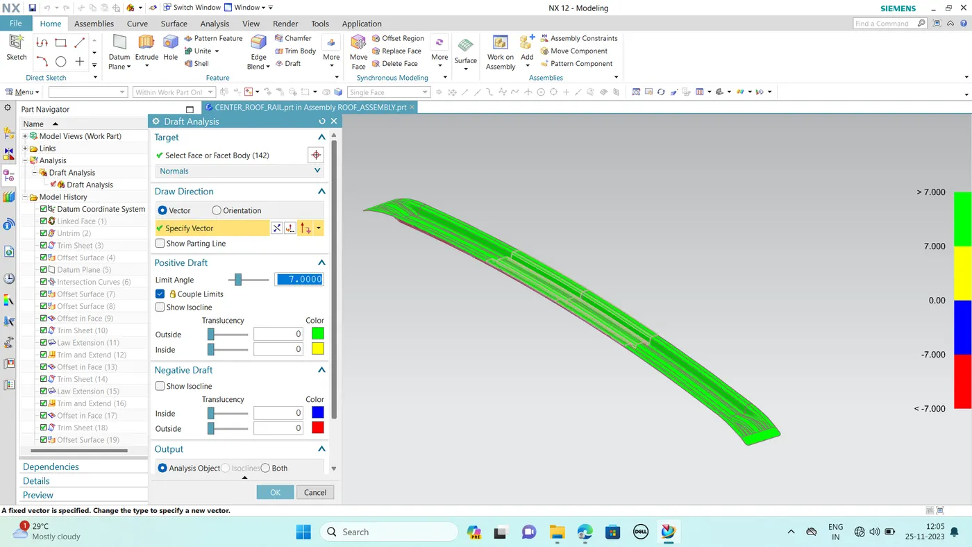
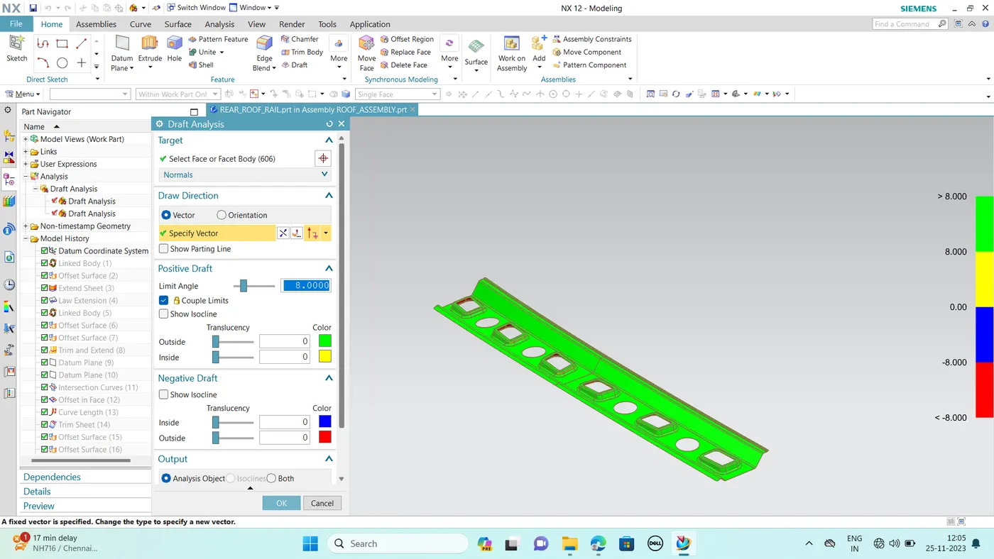
- Alos finding the draft analysis of each part.
DIFFERENT TYPE OF ROOF:
- Convertible
- Sunroofs
- T-tops
- Targa tops
- Vinyl
DESIGN CONSIDERATION:
- Roof outer
- Front roof rail
- Bow roof rail
- Centre roof rail and Reinforcement
- Rear roof rail
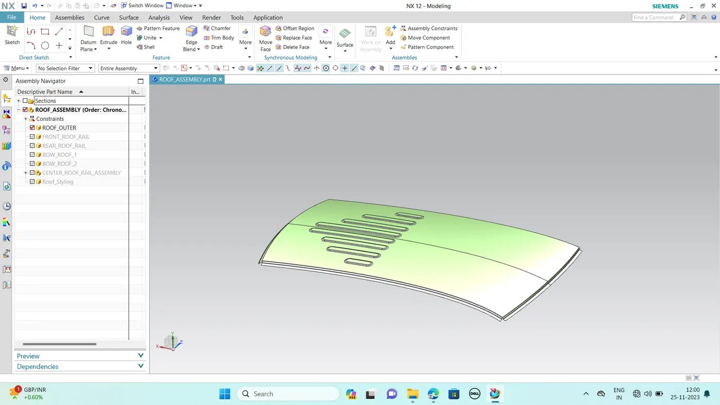
ROOF OUTER:
It is outer panel which is given by styling team. In this we are adding flange for outside, front and rear mountings.
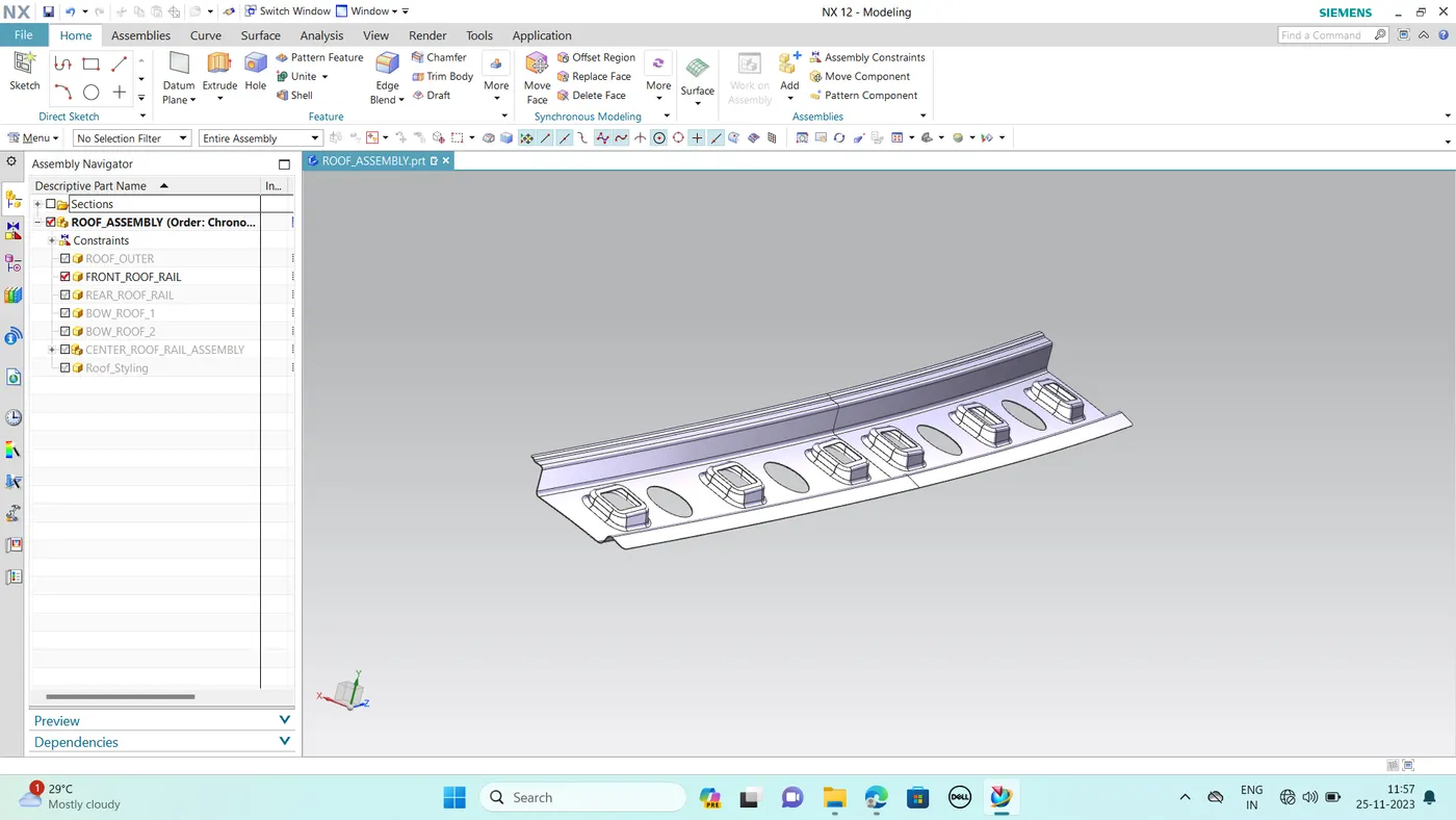
FRONT ROOF RAIL:
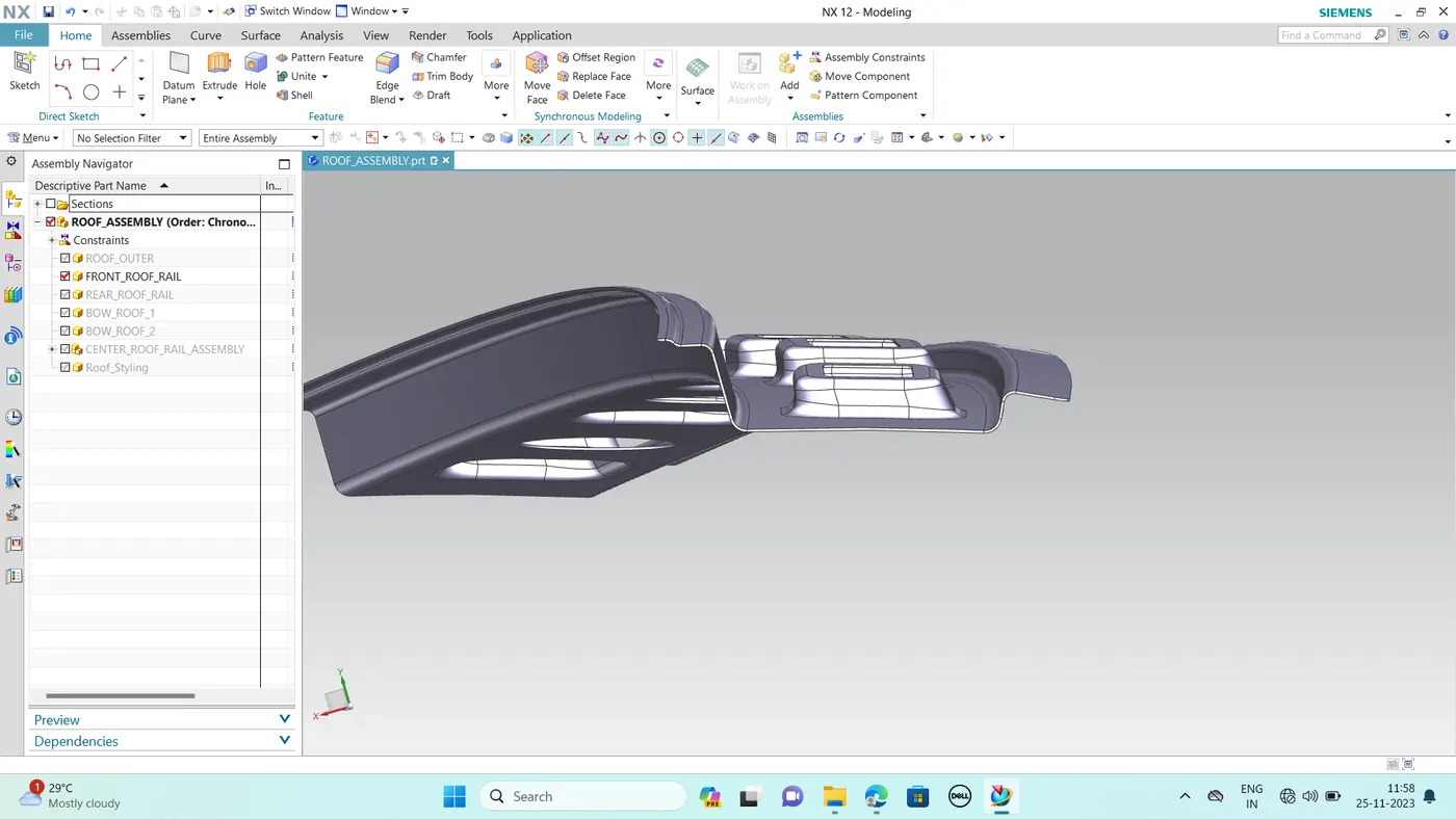
It is used to support windshield glass and inner panel. Design considering the visibility criteria of driver and passangers point of view. Windshiel end and roof end is joined using spot weld and other end is joined usingmastic sealents.
Embosses and cutout are given to increase strength and reduce the weight of part.
BOW ROOF 1:
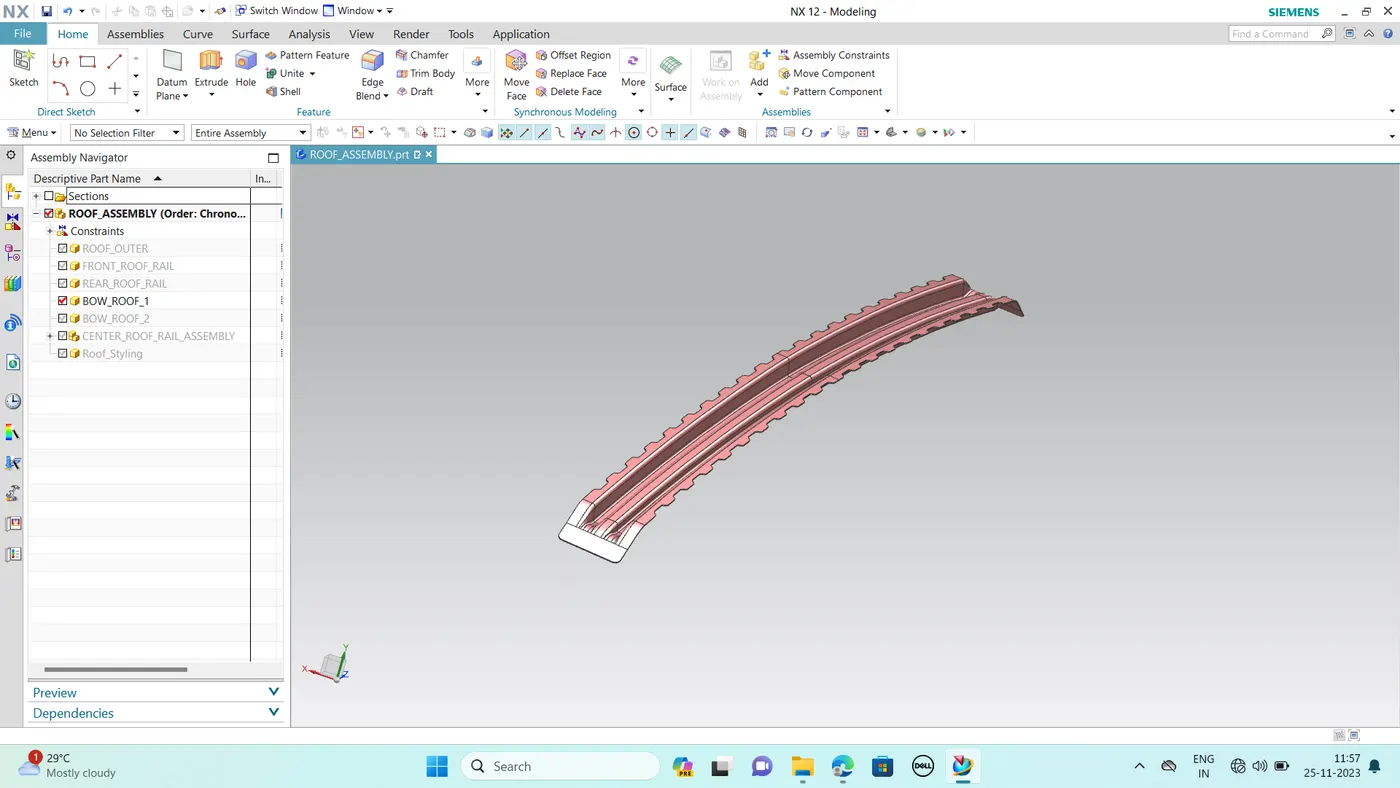
It is the part which is added to provide strength to the longer length roofs. Joined to roof with mastic sealent.
CENTRE ROOF AND REINFORCEMENT:
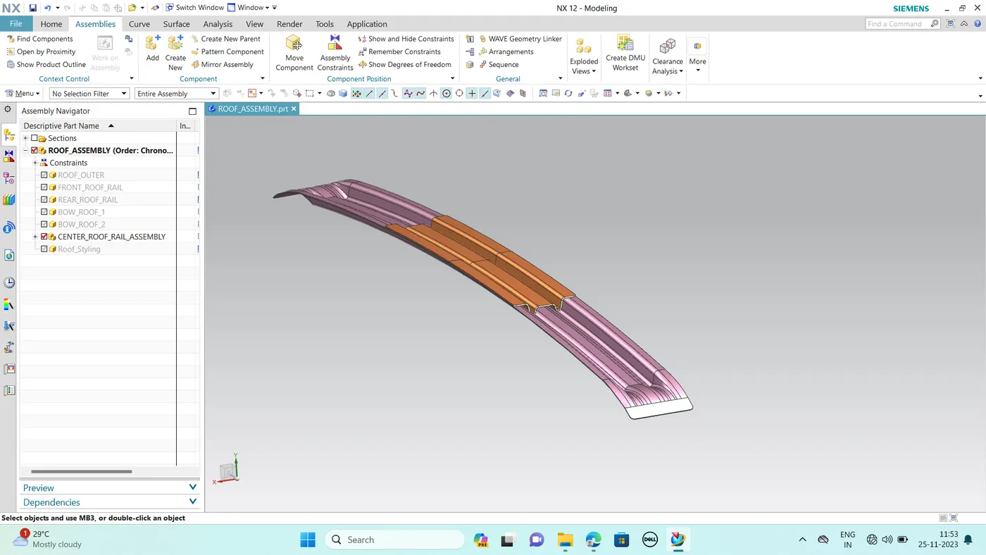
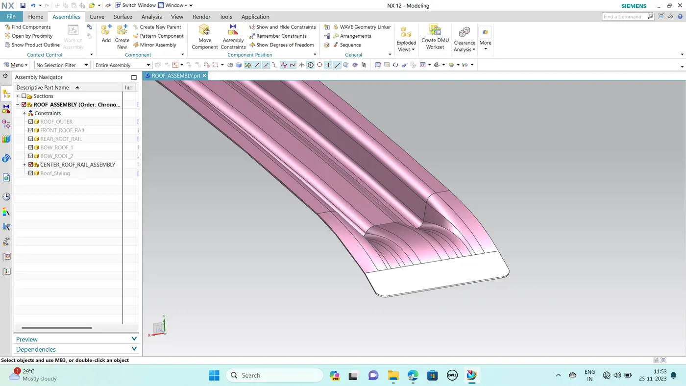
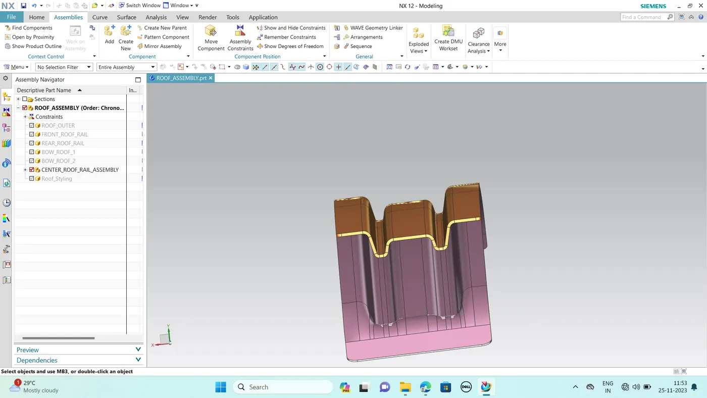
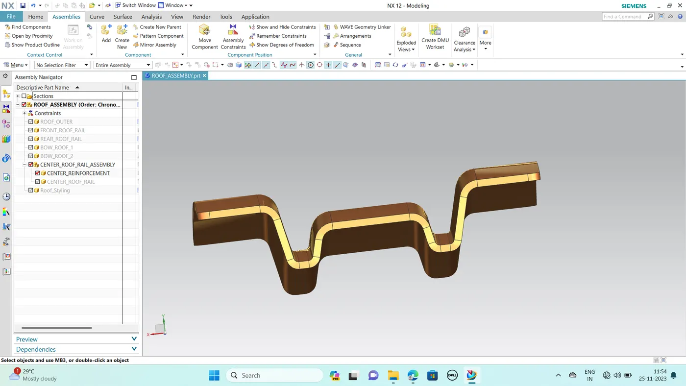
It is cross member that is used in between front and rear roof rails to give proper strength. Reinforcement is also designed to improve the strength having thickness of 1.5mm.
Joined with centre roof with spot welding. Centre roof rail is joined to outer roof by using mastic sealent.
BOW ROOF 2:
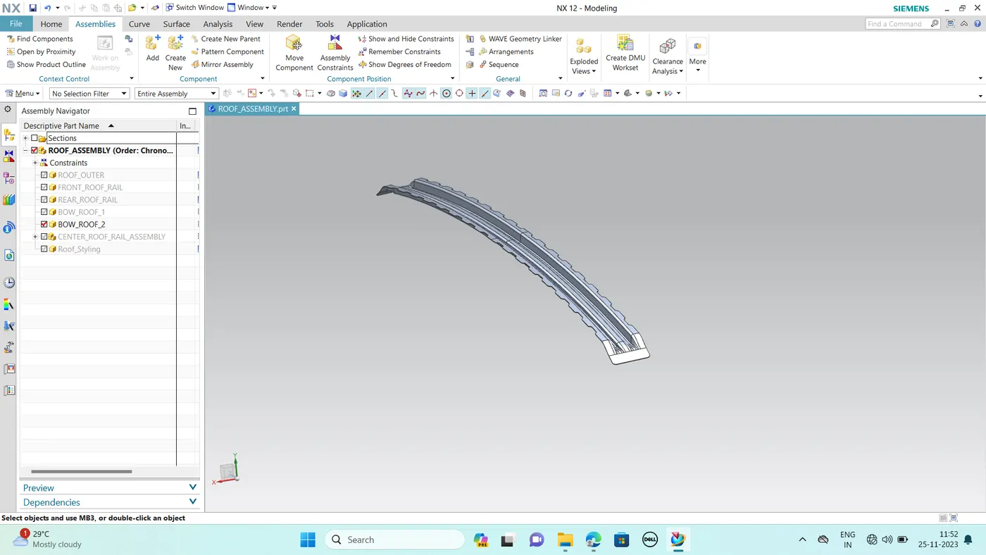
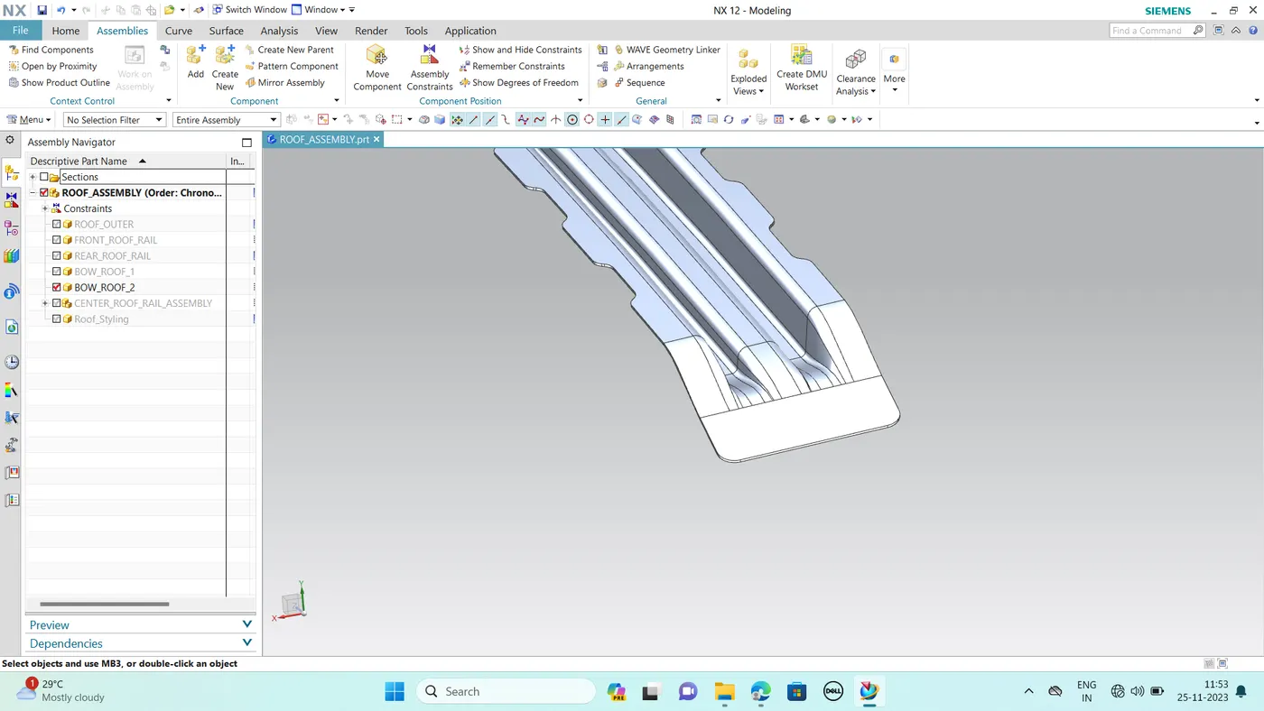
This part is added to provide strength to the longer length roofs. Joined to roof with mastic sealent.
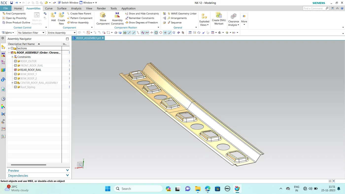
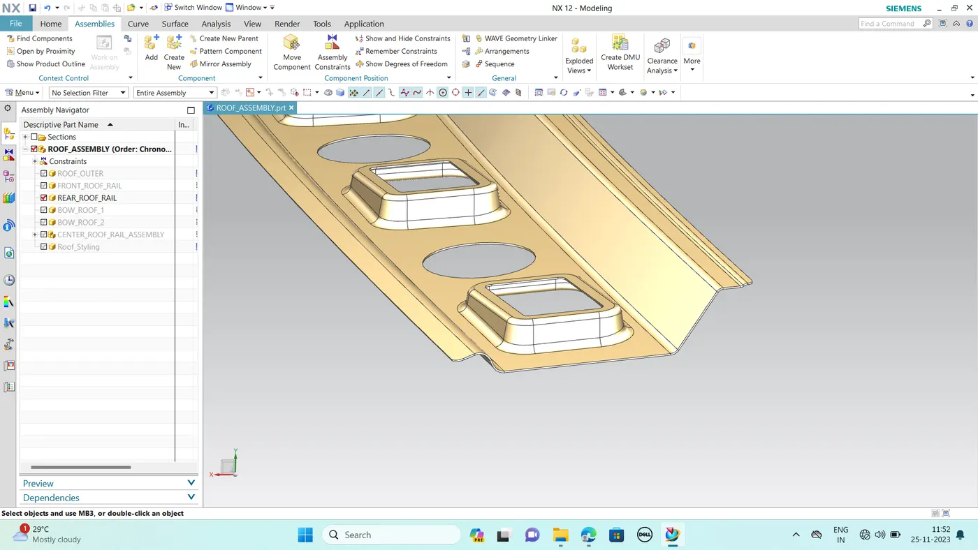
REAR ROOF RAIL:
It is used to support that joines the backdoor and outer roof with the help of spot welding and other end is joined to roof with mastic sealent.
Embosses and cutouts are given to increases strength and reduce the weight of part.
DITCH AREA:
It is nothing but adding flange to the styling surface for different mounting.
MASTIC POINTS:
SECTION MODULUS:
The section modulus of the cross sectional shape is significant importance in designing beams. It is a direct measure of the strength of the beam. A beam that has longer section modulus than another will be stronger and capable of supporting greater loads.
S = I/Y
1.FRONT ROOF RAIL:
2.BOW ROOF 1:
3.CENTRE ROOF AND REINFORCEMENT:
4.BOW ROOF 2:
5.REAR ROOF RAIL:
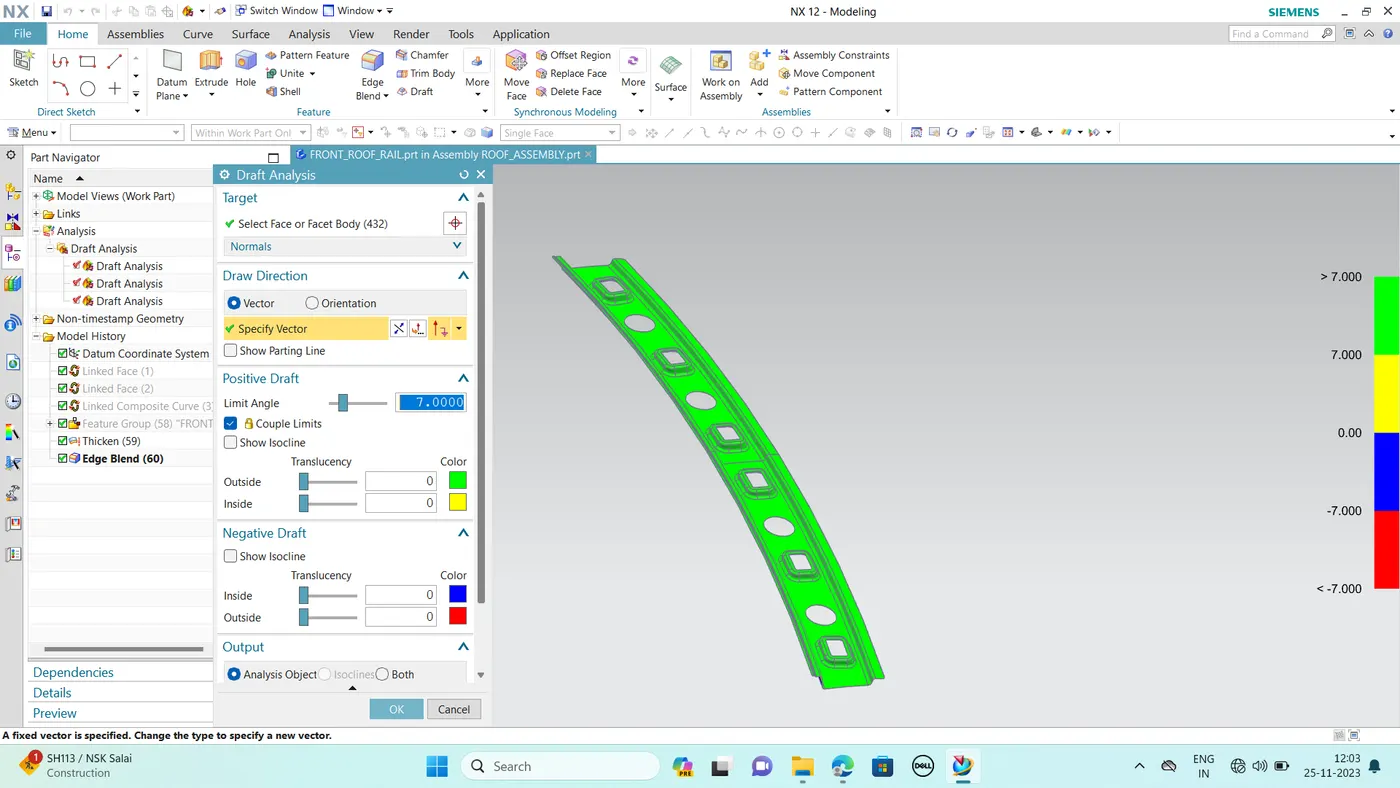
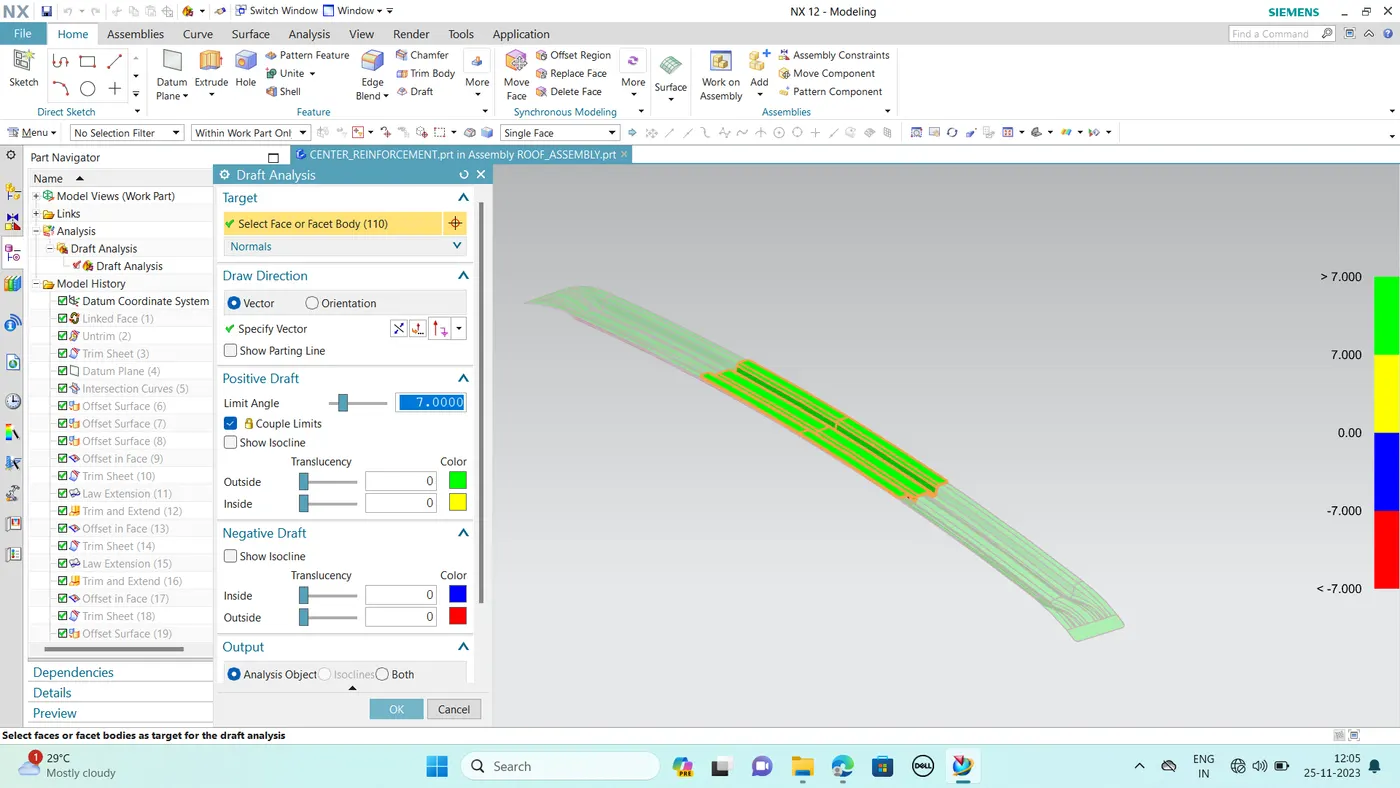
DRAFT ANALYSIS:
HEAT DISTORTAION CALCULATION:
W = [1.73 x 10^(-3) x L] + [1.85 x 10^(-8) x (R^2)/t] + [ 1.10x10^(-3) x l] - 2.68
Where,
L = Roof Length in X-Direction[mm](Roof dimension in 0-Y)
R = Roof curvature
R = 2(Rx*Ry)/(Rx+Ry)
Rx = X curvature
Ry = Y curvature
t = Roof plate thickness [mm]
l = Bow Roof Span [mm]
SNOW LOAD CRITERIA:
Qr = [Iy x t2] / [α x s x [(Rx + Ry)/2]2 x 10-8]
Note: The Qr value given over here is correct. There was a typo error in the formula given in the video.
Where,
α = My x Lx2 x 10-12 , My = Y(Ly-Y)
t = Roof plate thickness [mm]
Ly = Distance between the front and rear roof Rails on the Vehicle along with 0Y[mm]
Length of Roof panel with the center point between Roof rail Front /Rear as the front and rear reference point.
Lx = Distance between the Left and Right end of the roof on the Roof BOW [mm]
The width of the roof panel is exposed on the surface.
Y = Distance front Front Roof Rail to Roof BOW[mm]
s = Distance for which Roof BOW bears divided load [mm]
s = L1/2 + L2/2
Iy = Geometrical moment of inertia of Roof BOW (Y cross-section )[mm4]
Rx = Lateral direction curvature radius of roof panel Y cross-section on Roof BOW [mm]
Roof panel curvature Radius of the Length Lx in Front view
Ry = Longitudinal Direction curvature radius of the Roof panel X cross-section on Roof BOW [mm]
Roof panel X curvature radius of length s in Side view
FINAL VIEW: