Roof Design
AIM: To design & develop the Roof of a car with its components by following the master section and design parameters.
Introduction:
An automobile roof or car top is the portion of an automobile that sits above the passenger compartment, protecting the vehicle occupants from sun, wind, rain, and other external elements. Roof is the structure above the wind shield glass having the reinforcements to provide the strength to the overall structure and to with stand the over head forces like snow. It determines the appeal of the vehicle, the use, the type of people that would buy it, the places where it can go, and even the times when you can drive it.
Types of roofs:
- Hardtops
- Softtops
- Convertibles
- Hard top with sunroof , moon-roof and Panaromic sunroof
- Convertibles with Retractable hardtop and Detachable hardtop
Components Of Roof
- Front roof rail
- Bow roofs
- Central roof rail
- Rear roof rail
Manufacturing Process
Stamping:
Stamping (also known as pressing) is the process of placing flat sheet metal in either blank or coil form into a stamping press where a tool and die surface forms the metal into a net shape. Stamping includes a variety of sheet-metal forming manufacturing processes, such as punching using a machine press or stamping press, blanking, embossing, bending, flanging, and coining. This could be a single stage operation where every stroke of the press produces the desired form on the sheet metal part, or could occur through a series of stages. The process is usually carried out on sheet metal, but can also be used on other materials, such as polystyrene.
Joining Process:
Mastics are introduced between the roof outer panel and the reinforcements for joining . where ever the mastic are introduced there is remarkable improve of the strength and spot welding is also introduced to join the reinforcements with the outer panel.
Design Parameters:
- Visibility Criteria
- Head Clearance
- Curvature Study
- Heat Distortion and Snow Load Criteria
- Draft angle must be greater than
7 o
Crash test:
The design given by the IIHS ( insurance institute of highway safety ) . After analyzing the many accidents IIHS has then fixed some regulations , that how to perform the crush test .IIHS gives the rating based up on this test . For this they consider two points while giving the rating 1.How fast the car can reforms to its original shape after the roll over 2.How deep is the protrusion after the roll over.
HEAT DISTORTION CRITERIA
Heat distortion study is carried out to check the ability of the roof to withstand given fixed load. The heat deflection temperature or heat distortion temperature is the temperature at which a material starts deforms under a specified load. Above this temperature material cannot be used for application. This study plays an importantant role in sheet metal usage and also helps us to get the idea of where to position the bow roofs and centre roof rail in order to avoid bending or damages and there by gives strength to the roof.
Bow–Roof Prediction Formula
W = [1.73 x 10^(-3) x L] + [1.85 x 10^(-8) x (R^2)/t] + [ 1.10x10^(-3) x l] - 2.68
Where,
L = Roof Length in X-Direction[mm](Roof dimension in 0-Y)
R = Roof curvature
R = 2(Rx*Ry)/(Rx+Ry)
Rx = X curvature
Ry = Y curvature
t = Roof plate thickness [mm]
l = Bow Roof Span [mm]
Judgment Condition
OK< 2>
SNOW LOAD CRITERIA
Snow Load study is carried out to check the ability of the roof to withstand given fixed load during snow. During the snow fall, due to the weight of snow, the roof will dent inside. So the roof must be designed in such a way that after the removal of snow the roof must go to the original position.
Snow Load Prediction Formula
Qr = [Iy x t2] / [α x s x [(Rx + Ry)/2]2 x 10-8]
Note: The Qr value given over here is correct. There was a typo error in the formula given in the video.
Where,
α = My x Lx2 x 10-12 , My = Y(Ly-Y)
t = Roof plate thickness [mm]
Ly = Distance between the front and rear roof Rails on the Vehicle along with 0Y[mm]
Length of Roof panel with the center point between Roof rail Front /Rear as the front and rear reference point.
Lx = Distance between the Left and Right end of the roof on the Roof BOW [mm]
The width of the roof panel is exposed on the surface.
Y = Distance front Front Roof Rail to Roof BOW[mm]
s = Distance for which Roof BOW bears divided load [mm]
s = L1/2 + L2/2
Iy = Geometrical moment of inertia of Roof BOW (Y cross-section )[mm4]
Rx = Lateral direction curvature radius of roof panel Y cross-section on Roof BOW [mm]
Roof panel curvature Radius of the Length Lx in Front view
Ry = Longitudinal Direction curvature radius of the Roof panel X cross-section on Roof BOW [mm]
Roof panel X curvature radius of length s in Side view
Judgment condition
Qr ≥ 3.1
250 ≤ s ≤ 380
Master section
Master sections are the crosssection of 3D model. These master sections are widely used in OEMs and in automotive industries to convey the functional requirements of commodity to the design engineer. It gives the parameters like length, width, height, radius and clearance should be considered while designing the particular part or component
Front Roof Rail Master section
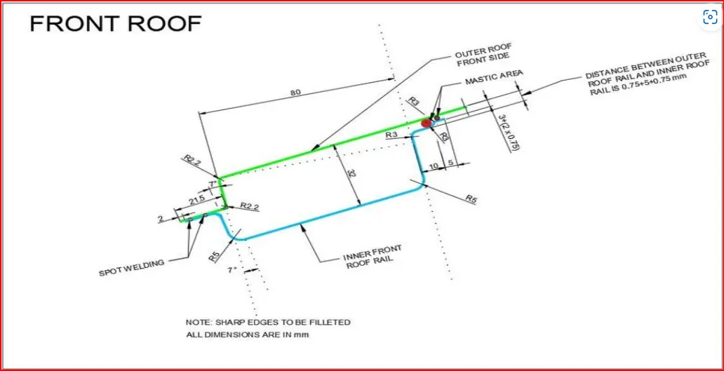
The verticle flange is given at 7° followed by the given class A curvature surface. And the distance between the outer roof panel and inner front roof rail is given 32mm. Also the front side the ditch area is given 21.50mm in the outer roof and for the inner front roof rail it is reduced by 2.00mm here at this end there is Spot welding is shown so, there is no any gap between the outer roof and inner front roof rail. Also the blend of the corner dimensions are given at diiferent edges. In the end of the inner front roof rail the 10.00mm and 5.00mm distance horizontal flange are given where the MASTIC Sealant is used. So Area is given for mastic joint is 3.00mm and 5.00mm.The front roof rail is used as the reinforcement to the roof surface to increase the strength and also used to mount the brackets for some features such as room lamp or map lamp and rear mirror. The depth of the front roof rail is decided based on the visibility criteria line decided for the driver visibility. The width of the front roof rail is decided in such a way that there should be enough headroom clearance between the head of the driver and the end surface of the roof rail to avoid injuries to the person.
Master section of the Rear Roof Rail
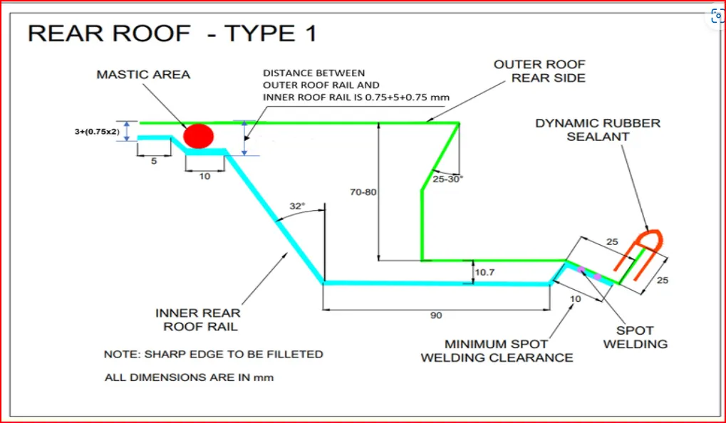
The outer roof panel rear flange should have the negative flange of 25° - 30° draft to accommodate the clearance for back door movements. The overall hight of the rear flange must lie between 70-80mm. The Dimenstions for rear roof rail are offset of (3+0.75+0.75) & (0.75+5+0.75) for front flanges, which is given because of Mastic Area. and the 10.7mm for the offset of center emboss and its width is 90mm. Then the draft angle for emboss connecting the front flange is 32°. Here in the rear area of the rear roof rail is SPOT welded to the outer roof so there is no gap maintain between them at this area.
Master section of Bow Roof
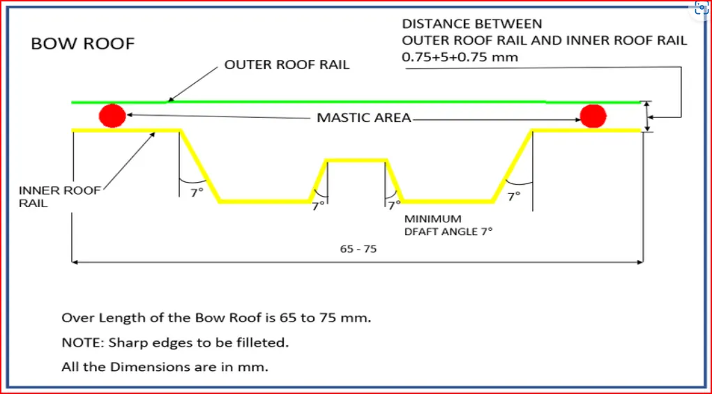
Here, the overall width of the bow roof should lie between 65-75mm and all the embosses have atleast 7° of positive draft with respect to the tooling direction. Then the offset of bow roof outer flange is 0.75+5+0.75mm from the roof outer panel because of the Mastic Area.
Master section of Center Reinforcement Rail
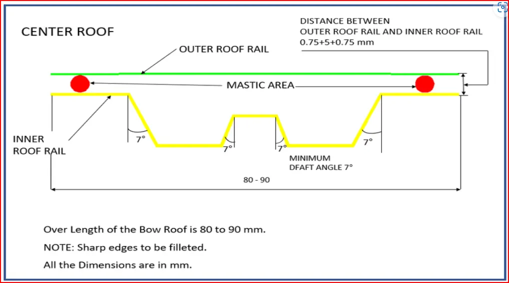
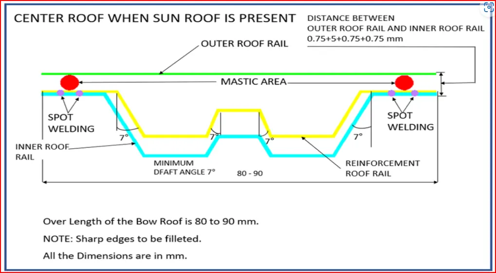
Same as the bow roof, the overall width of the center roof should lie between 80-90mm and all the embosses have atleast 7° of positive draft with respect to the tooling direction. Then the offset of center roof outer flange is 0.75+5+0.75mm from the roof outer panel because of the Mastic Area.
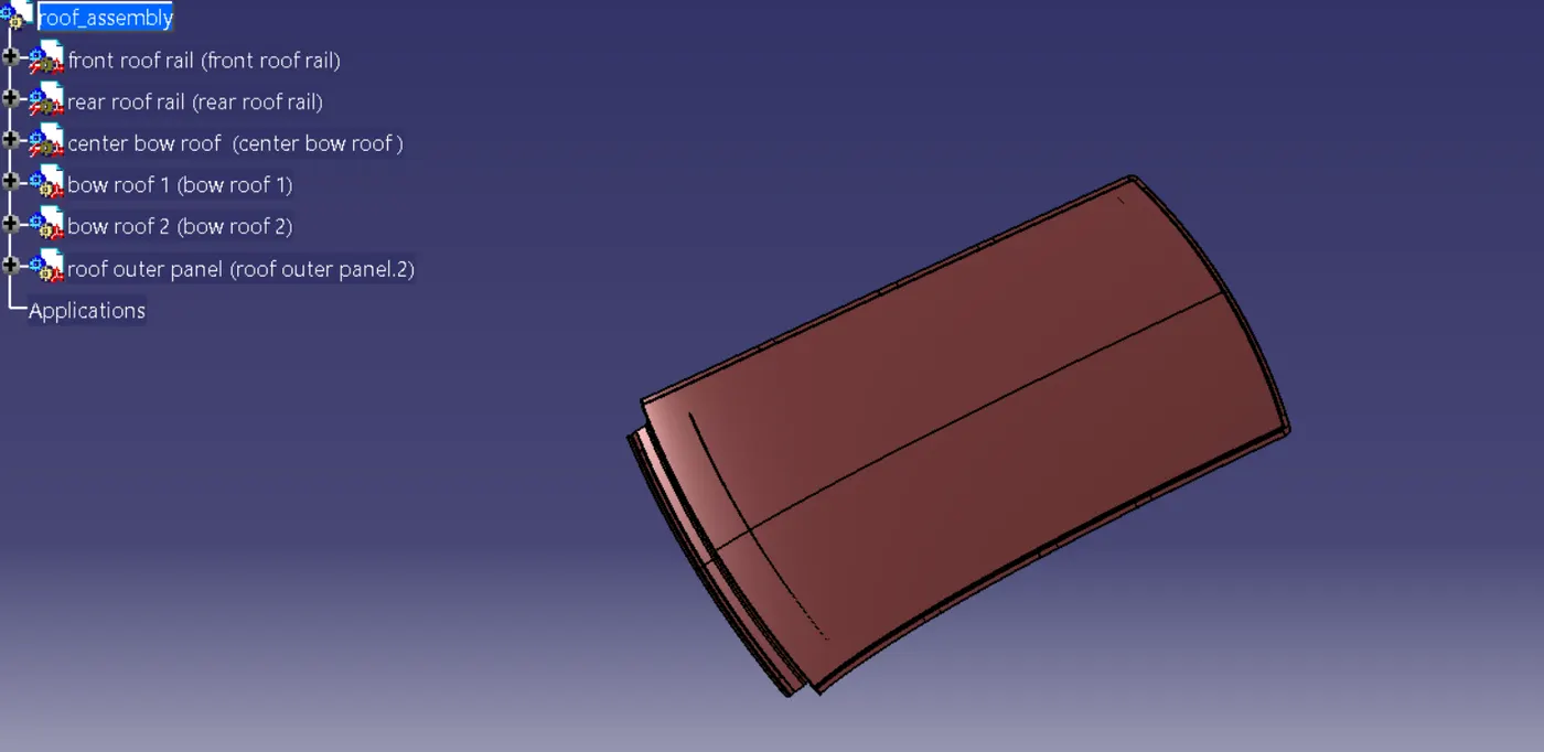
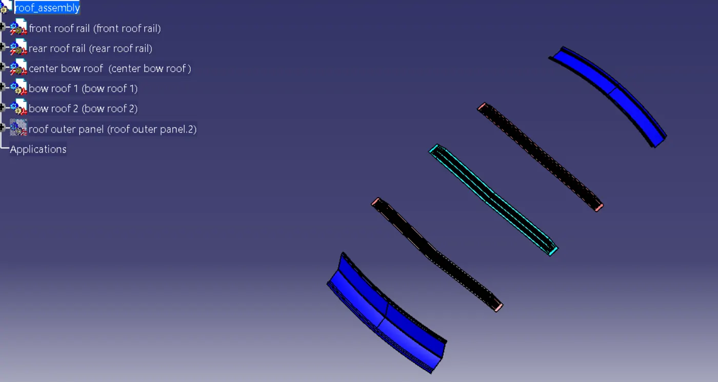
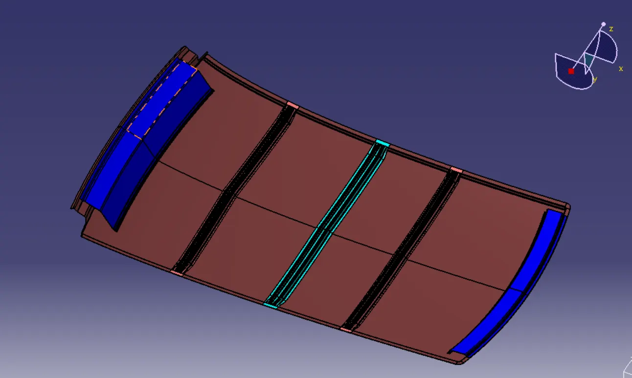
Roof Design Assembly
DRAFT ANALYSIS
Draft Analysis is carried out to check whether the designed part can be practically manufactured or not. Here Green and Yellow are acceptance limits, Blue and Red are NG. For the analysis, minimum draft angle of
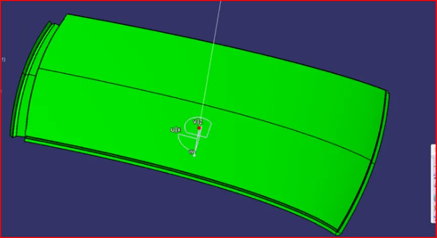
Conclusion:
The roof design considering all the design parameters and master section has been completed.
Thankyou.