Roof Design
ROOF DESIGN
Objective:-
Design car roof for the given class A by following the master-sections that are provided. and complete the heat distortion calculation, snow load prediction and draft analysis for each componenets.
Car Roof
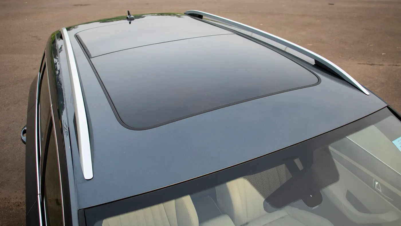
roof is a significant in car and all other vechicles, which play major role in both safety and astheticaly. simpley roof is a metal sheet panel layer that sit above the passenger compartment which will protect and keep everything inside safe from wind, rain, sun and all other external elements accidents etc.
and there are different types of roof are used in car industry acording to their needs, sun roof, hard roof, soft roof and convertable roof are some them
beside from the external panel that we see from the aesthetic side, the rood as other reinforcement components below the outer panel which will give strength to the outer panel and accumulate the safety consideration.
Main Components of car roof:
1. Outer Panel
2. Front Roof Rail
3. Center Roof Rail
4. Bow Roof Rail
5. Rear Roof Rail
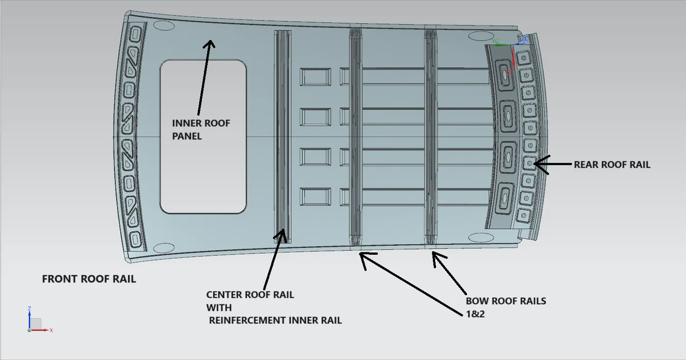
1. OUTER PANEL
the outer panel is the main component in roof assembley. all the other components are provide for the reinforcement of outer panel. outer panel protect passegers from wind, rain, sun and accidents. and also perform a major role in airodynamic.
the given styling surface has been extented as per the master section to get the ditch area where the outer panel is connected to the other panels of car body with a good sealing.
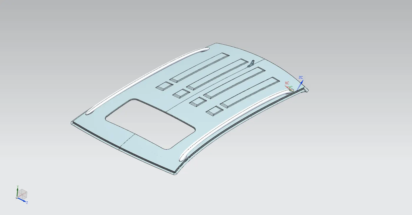
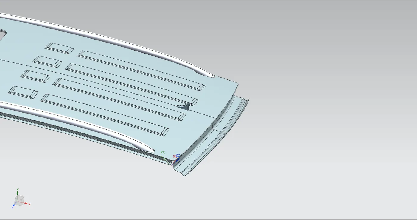
2. FRONT ROOF RAIL
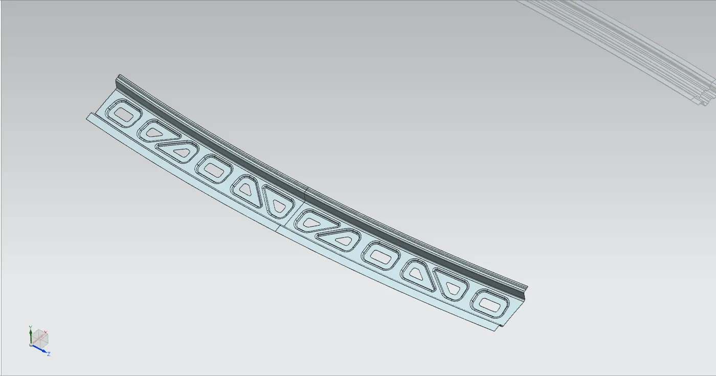
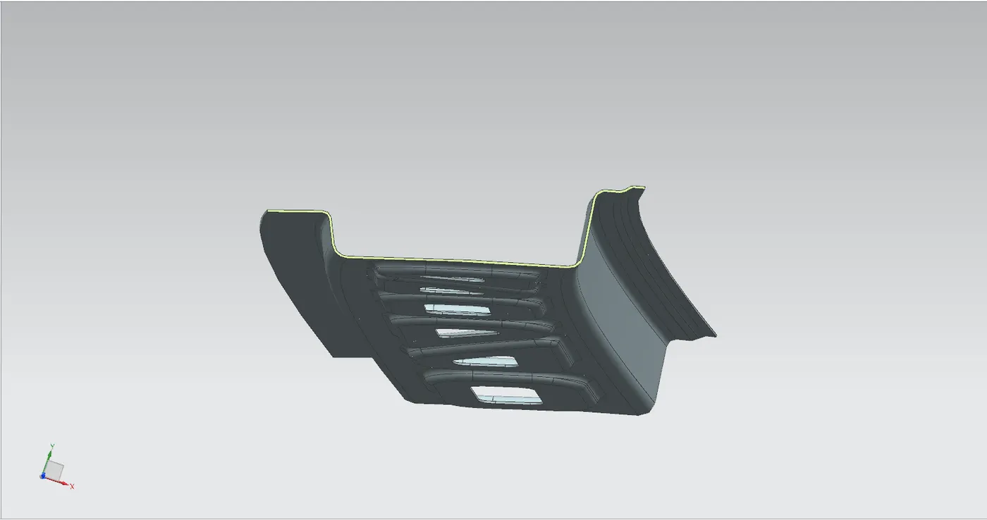
the front roof rail has designing according to the master section by considering all design consideration such as videcility criteria, head room clearance, thickness of wind shield glass and the thickness mastics will be used.
front roof rail is located on the front end of the outer roof panel, where it will be conected to the A piller of the car. to join the front rail with the outer panel spot welding will be used on the ditch area and mastic gum will be used on the asthetic area.
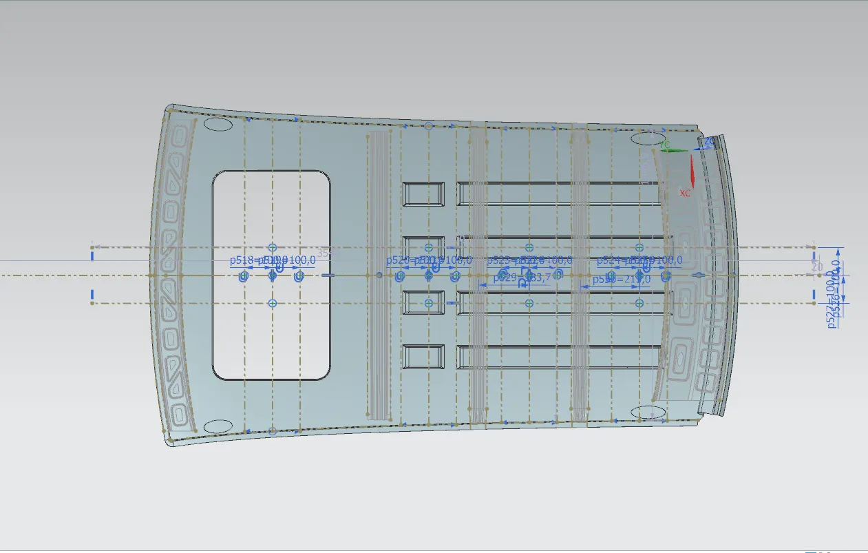
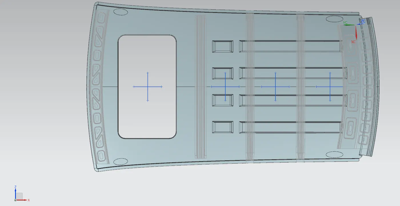
we also give some embosses in the front roof panel where it have flat surface. these embosses will help to increase the strenght of that area and also we give cutout inside the emboss which will also help to reduce the weight of the component
3. CENTER ROOF RAIL
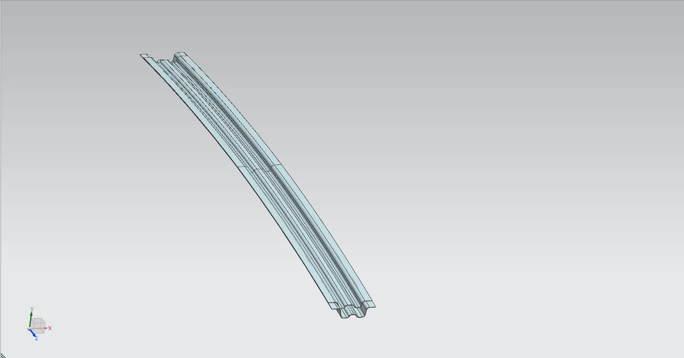
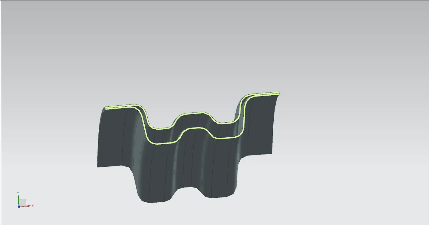
it has been designed according to the master sections and also following the design consideration. center roof rail will be located around the B piller region the caand here we designed the center rail with a reinfircement roof rail because the sunroof is present.
reinforcement inner roof rail:- it is a aditional roof rail which will be placed between outer roof rail and center roof rail. it provide as a reinforcement when the sunroof is present in the car, as we cut off a portion of the roof that area will be weak. so the reinforcement roof rail will be help to retain the strength
center roof rail with inner reinforcement roof rail
4. BOW ROOF RAIL
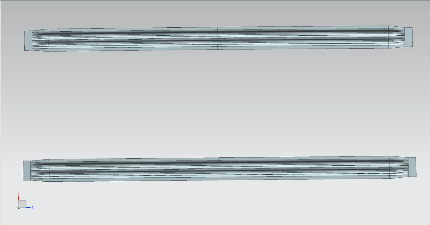
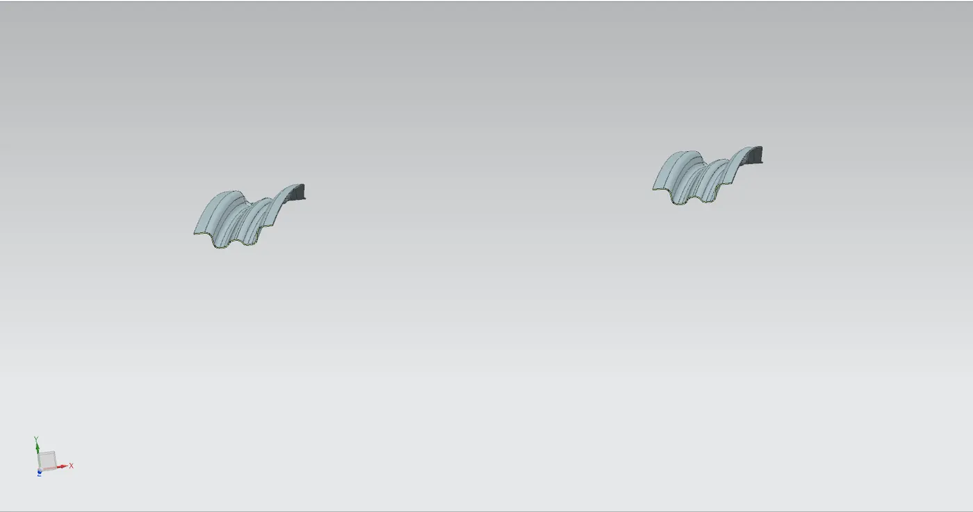
bow rail are provided to give extra strength the car outer roof panel. there will be one or more bow roof rail in a car, the number of bow roof rail is depented on the length of the car roof. the position of bow roof rail is depented on need that the car required
in this design the we have provided 2 bow roof rail where both are located in between the center roof rail and rear roof rail, because we have provide cutout for sunroof. and also we have give reinforcement roof rail to the center roof rail.
5. REAR ROOF RAIL
rear roof rail has been designed by considering the master sections. it is a very crucial part, while designing the rear roof rail we need to consider the ditch area and the tail gate door mounding requirments.
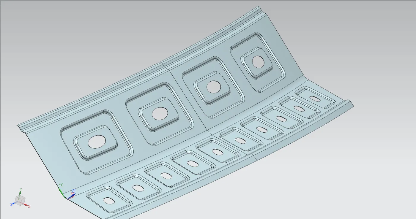
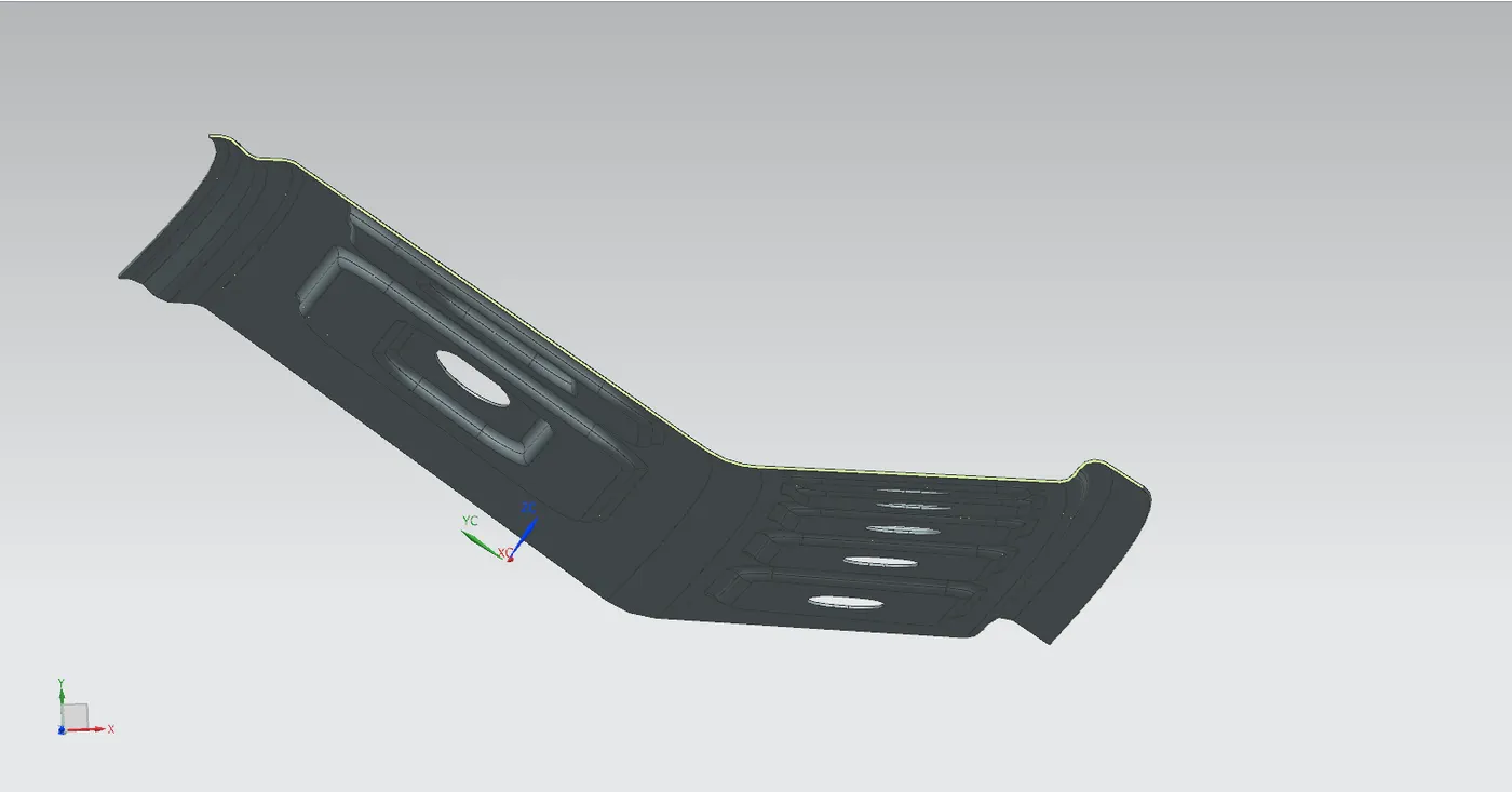
we also give some embosses and cutouts in the rr roof panel also as in the front roof rail
-----------------------------------------------------------------------------------------
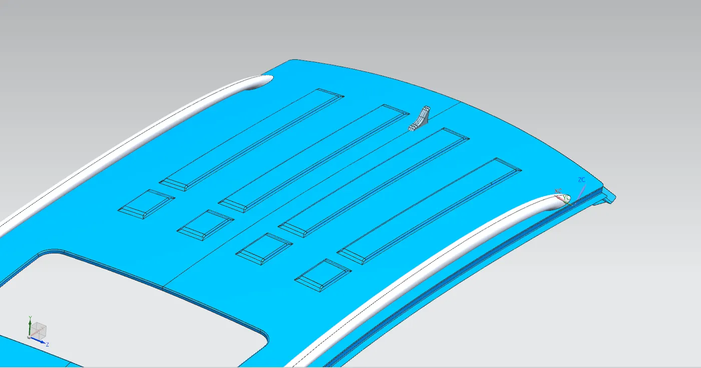
EMBOSSES ON ROOF
we have provide emboses on the which will increace the strength, also give a stylish look on roof and get a improved aerodynamics
in the roof outer panel we didint give styling emboss on the front side because we have consider sunroof varients for this car model.
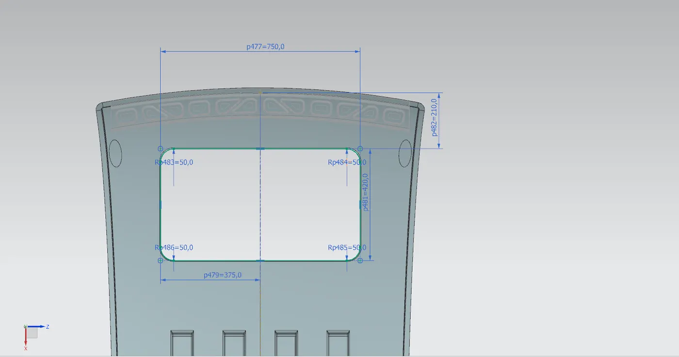
SUNROOF CUTOUT
while designing the roof panel we have considered sunroof varients for this car and give cutouts on the roof.
and also give an extra inner roofrail along with the center roof rail which will which will balance the strength loss due to the sunroof cutout.
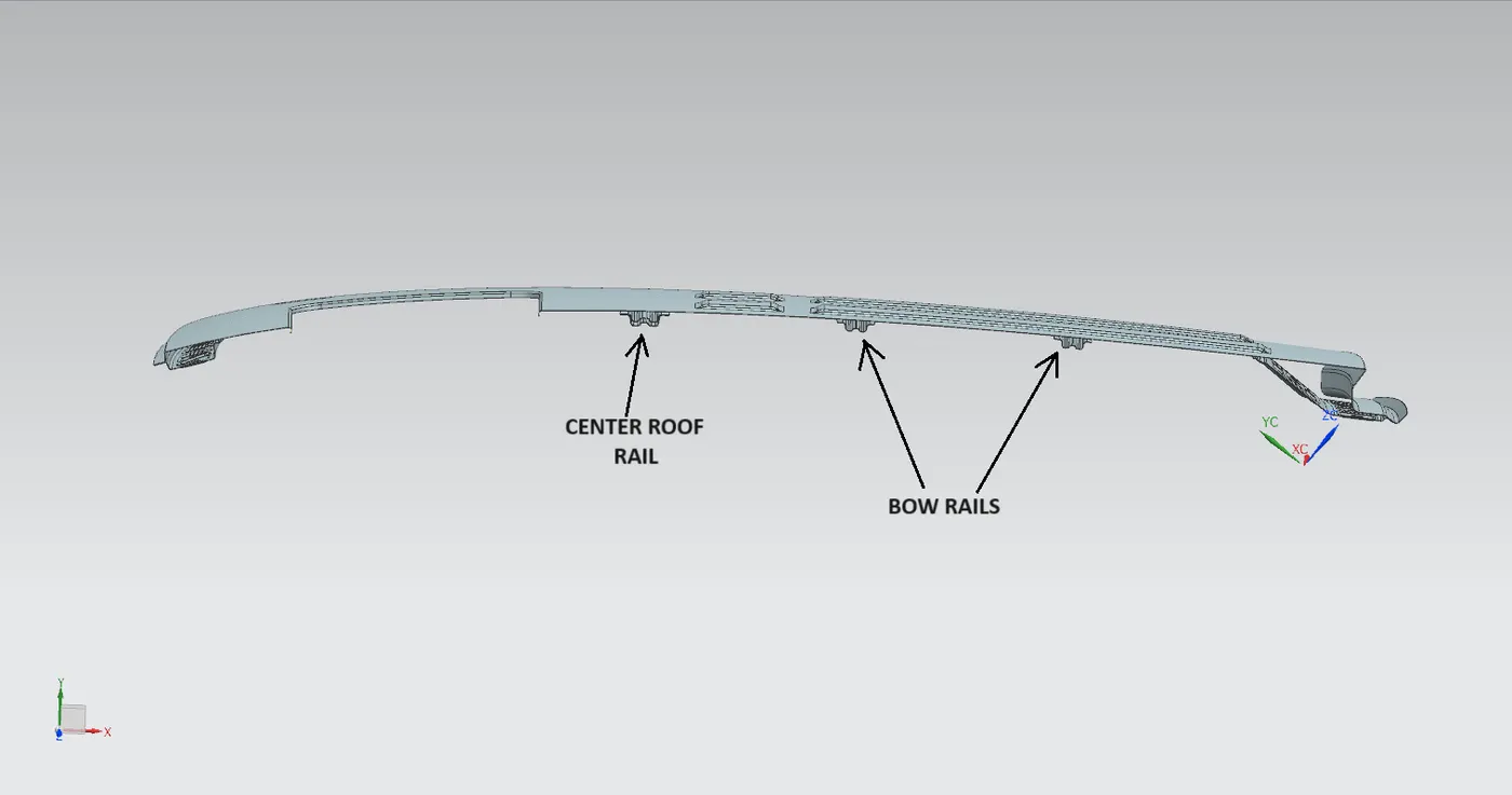
ROOF RAIL POSITIONING
- as we know from the master section the front and rear roof rails will be the positioned in both end as it should be.
- the center roof rail will be position as same as the position of 'B' piller and when we look in the cars we can see that the distance from A to B piller is less the distance between B & C PILLER
- so the center roof rail we have positioned little closer to the front roof rail.
- in our roof panel we gave sunroof cutout and a reinforcement for the center roof rail so we will not be need to give a bow roof rail between front and center roof rail.
- when we observe the outer roof panel its has more curvior on the front half portion and have a flat rear half portion, so we decide to give 2 bow roofs between the center roof rail and rear roof rail.
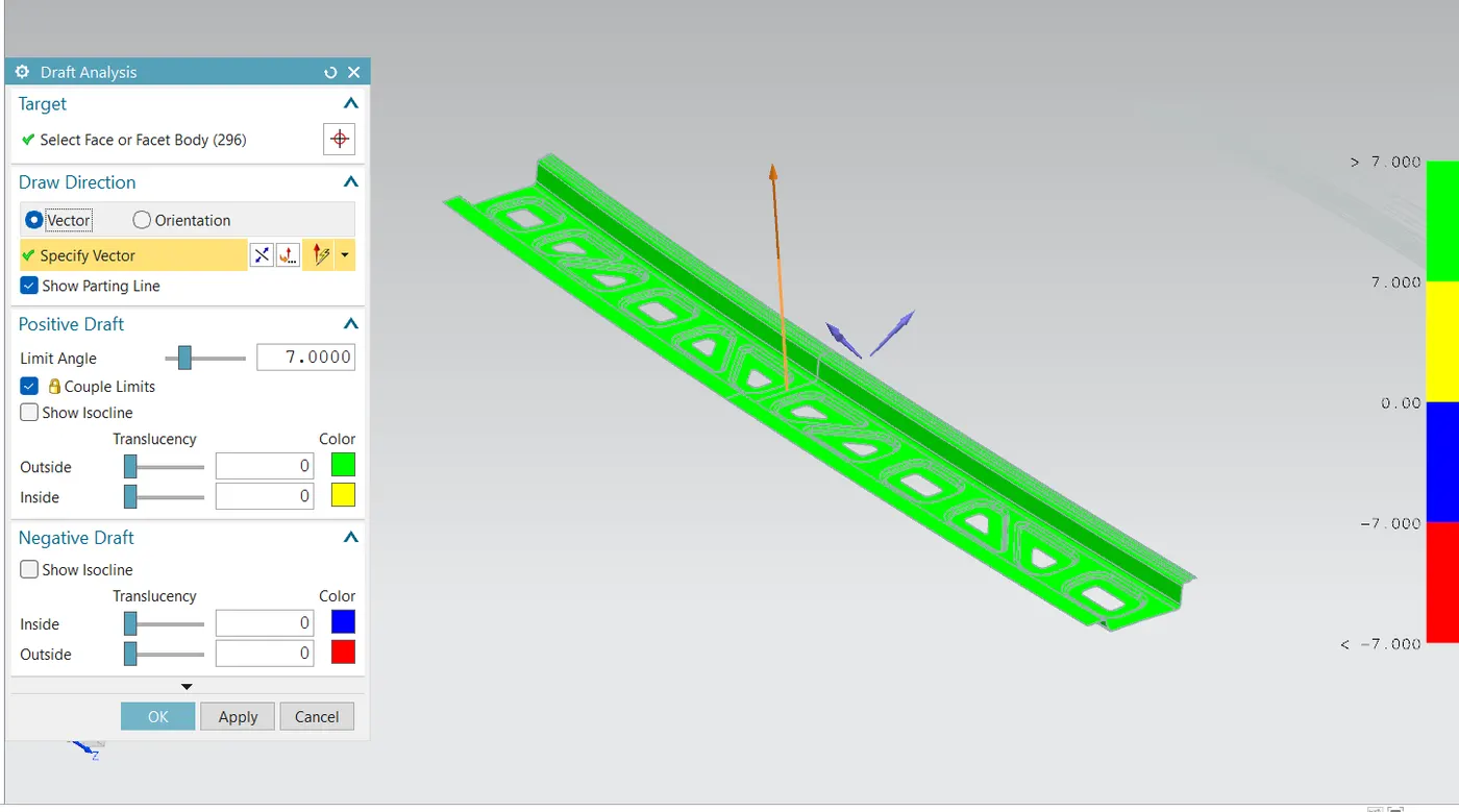
DRAFT ANALYSIS
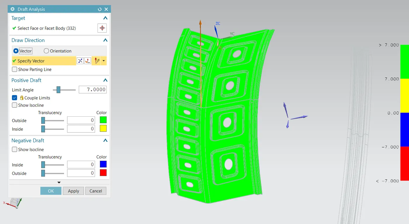
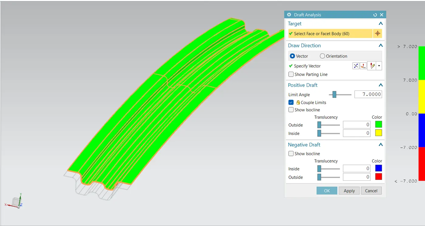
draft analysis has been done for every components and conform the every component is manufaturable with a minimum draft angle of 7 degree
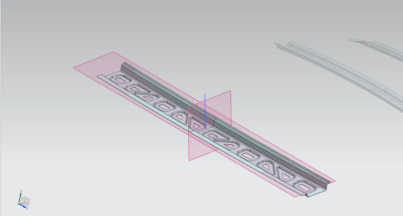
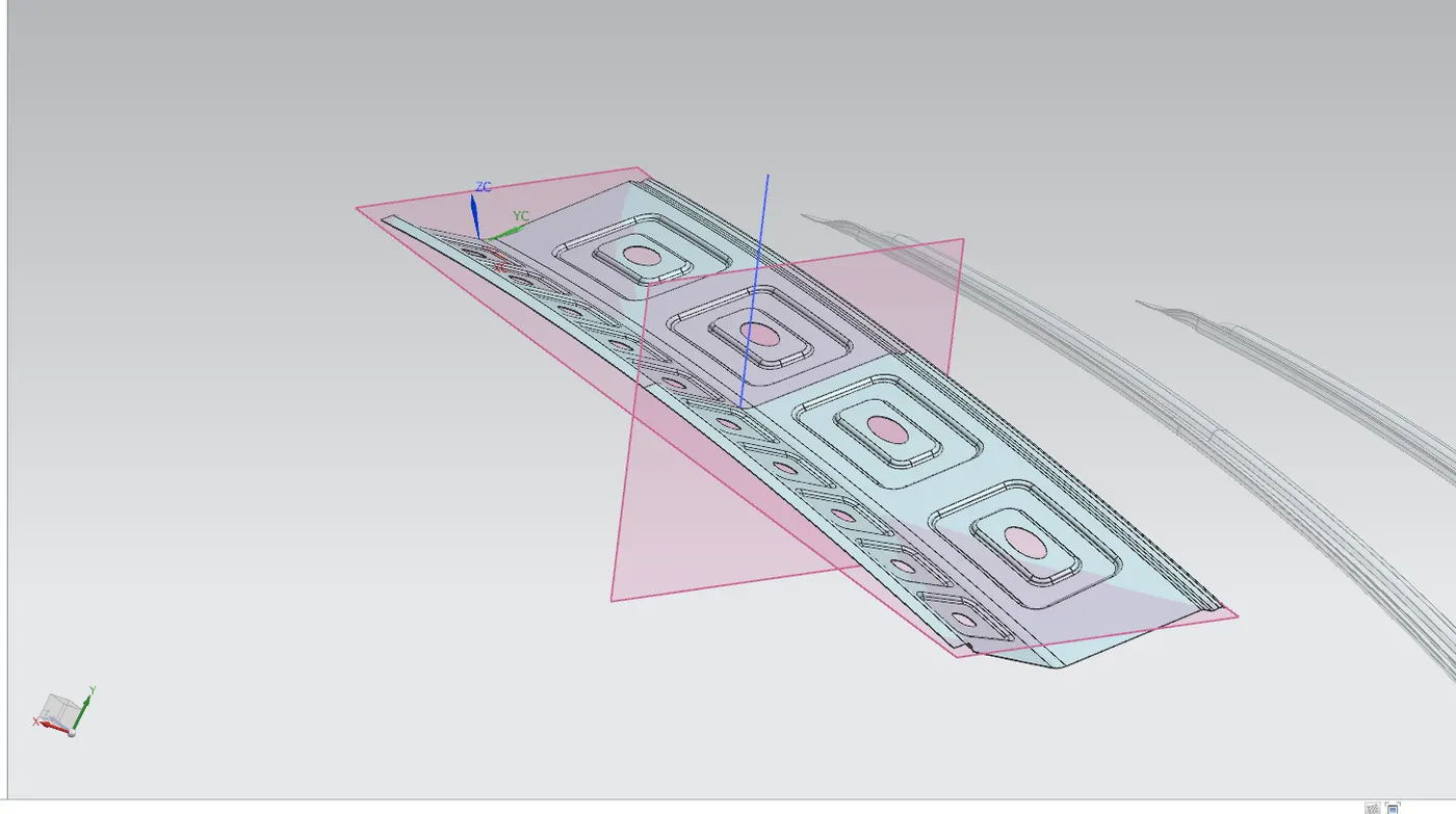
for the center roof rail, reinforcement roof rail and the both bow roof rail is the draft direction is taken as vertical axis. but for the front roof rail and rear roof rail the vertical axis wont clear the draft angle so we created seperate draft direction for the both of them, the images of them has provided below.
front roof rail:-
rear roof rail:-
center roof rail:-
center roof rail inner rail:-
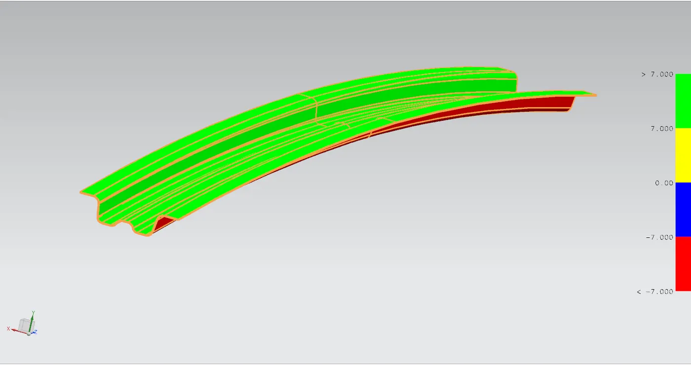
bow roof rails:-
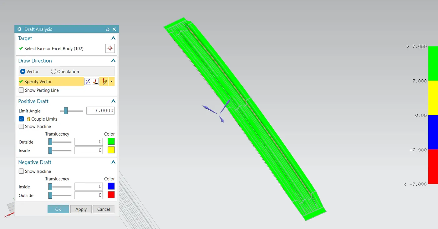
-------------------------------------------------------------------------------------------------------------------------
HEAT DISTORTION CRITERIA
this is a study conducting to find out th eability of roof to with stand at high temprature with respect to the positioning of reinforcement's provided in the roof panel which provided to increse the strength
the hear distortion criteria formula and calculation have given down
W = [1.73 x 10^(-3) x L] + [1.85 x 10^(-8) x (R^2)/t] + [1.10x10^(-3) x l] - 2.68
judgement condition = ok<2>
Were,
L = Roof Length in X-Direction[mm](Roof dimension in 0-Y)
R = Roof curvature
R = 2(Rx*Ry)/(Rx+Ry)
Rx = X curvature
Ry = Y curvature
t = Roof plate thickness [mm]
l = Bow Roof Span [mm]
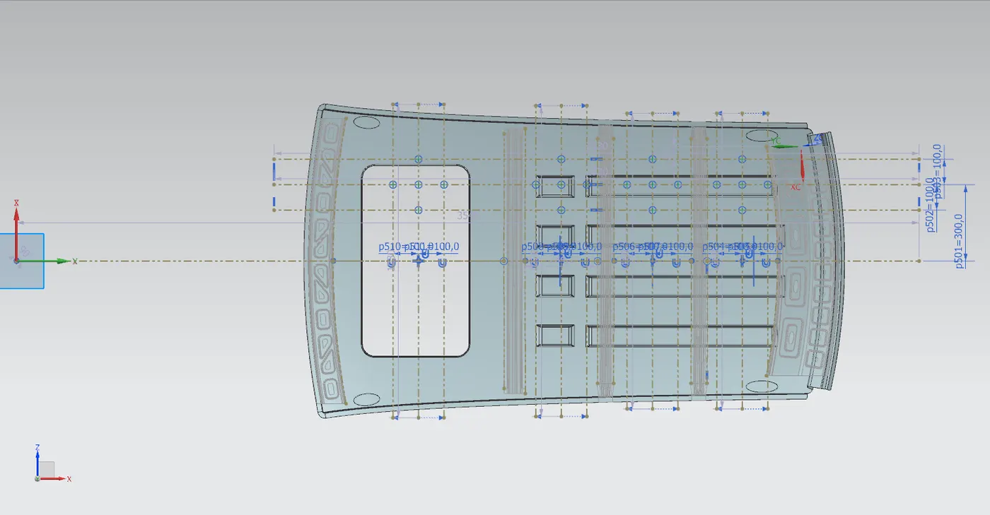
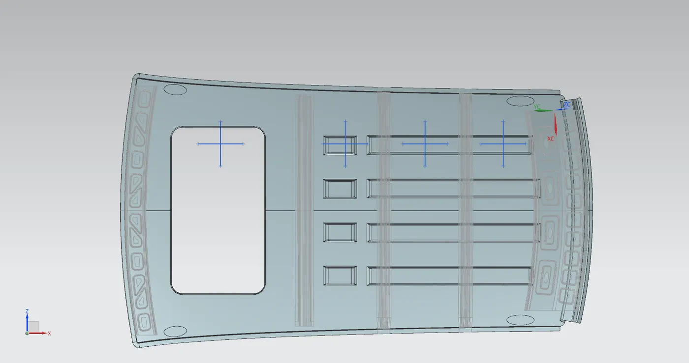
W for first case
L= 2031.115533545
t= 0.75
i= 673.702277530
RX= 5605.654070911
RY= 3593.463870918
R= 2(5605.654070911*3593.463870918)/(5605.654070911+3593.463870918)
= 4,379.488
W = [1.73 x 10^(-3) x L] + [1.85 x 10^(-8) x (R^2)/t] + [1.10x10^(-3) x l] - 2.68
= [1.73 x 10^(-3) x2031.115533545 ] + [1.85 x 10^(-8) x (4,379.488^2)/0.75] + [1.10x10^(-3) x 673.702277530] - 2.68
= 3.51382987303285 + 0.4732 + 0.741072505283 - 2.68
= 2.048
| sl | Bows | Rx | Ry | R | I | L | t | w | OK/NG |
| 1 | FR & CTR | 5605.65 | 5605.65 | 4,379.48 | 673.70 | 2031.11 | 0.75 | 2.048 | OK |
| 2 | CTR & 1ST | 4489.619 | 4489.61 | 5,794.9 | 284.46 | 2031.11 | 0.75 | 1.98 | OK |
| 3 | 1ST & 2ND | 3846.1 | 5,733.96 | 5,733.96 | 304.43 | 2031.11 | 0.75 | 1.98 | OK |
| 4 | 2ND & RR | 3322.38 | 14311.95 | 5,392.87 | 274.7 | 2031.11 | 0.75 | 1.86 | OK |
So after the heat distortion criteria calculation we can see all the values have come under the given judgement condition, so our design have a good heat distortion criteria.
----------------------------------------------------------------------------------------------------------------------------------
SNOW LOAD PREDICTION
the snow load prediction simulation and calculations are done on car roof is to ensure that the roof design can withstand the weight of heavy snow during winter in snowing regions and its ability to return to its original position after the snow is removed.
snow load rediction fourmula
Qr = [Iy x t2] / [α x s x [(Rx + Ry)/2]2 x 10-8]
judement condition = qr < 3>
Where,
α = My x Lx2 x 10-12 , My = Y(Ly-Y)
t = Roof plate thickness [mm]
Ly = Distance between the front and rear roof Rails on the Vehicle along with 0Y[mm]
Length of Roof panel with the center point between Roof rail Front /Rear as the front and rear reference point.
Lx = Distance between the Left and Right end of the roof on the Roof BOW [mm]
The width of the roof panel is exposed on the surface.
Y = Distance front Front Roof Rail to Roof BOW[mm]
s = Distance for which Roof BOW bears divided load [mm]
s = L1/2 + L2/2
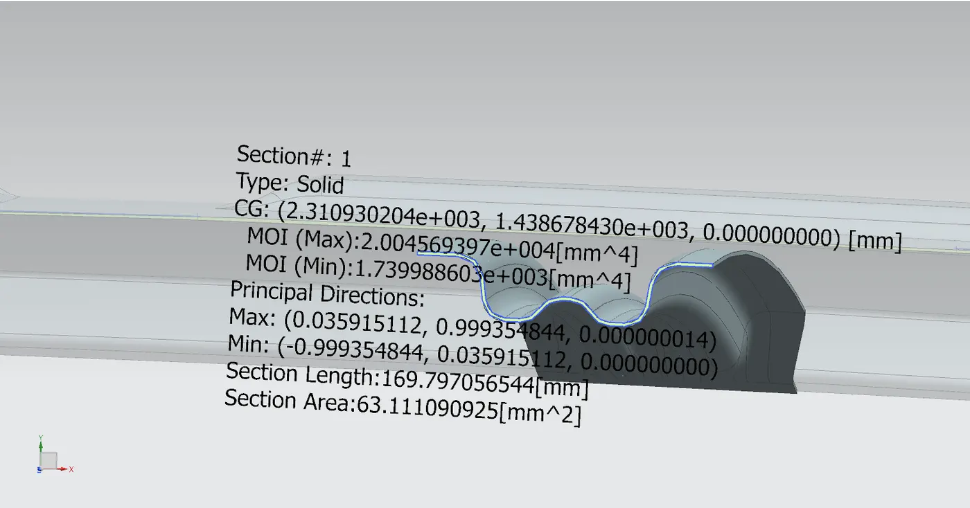
Iy = Geometrical moment of inertia of Roof BOW (Y cross-section )[mm4]
Rx = Lateral direction curvature radius of roof panel Y cross-section on Roof BOW [mm]
Roof panel curvature Radius of the Length Lx in Front view
Ry = Longitudinal Direction curvature radius of the Roof panel X cross-section on Roof BOW [mm]
Roof panel X curvature radius of length s in Side view
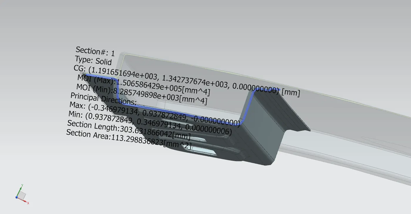
moment of inertia front roof rail:-
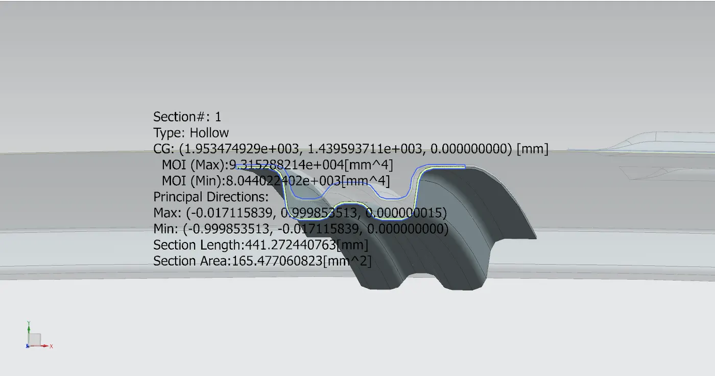
moment of inertia center roof rail:-
moment of inertia bow roof rail:-
------------------
case1
Qr = [Iy x (t)2] / [α x s x [(Rx + Ry)/2]2 x (10)-8]
α = My x LX2 x 10-12 , My = Y(Ly-Y)
= 8,83,971.8 * (1122.18)2* (10)-12
= 1.11 MY = 768.07(1918.97-768.07)
= 8,83,971.8
L1= 768.07
L2= 357.62
s = L1/2 + L2/2
= (768.07/2) + (357.62/2)
= 562.845
T= 0.75
Ly= 1918.97
Lx= 1122.18
IY= center roof= 8.045 (10)3
Y= 768.07
RX= 3976.81
RY= 16563.36
Qr = [Iy x (t)2] / [α x s x [(Rx + Ry)/2]2 x (10)-8]
= 4,525.3125 / 658.96
= 6.9
| sl | bows | ly | a | lx | ly | y | s | rx | ry | t | Qr | ok/ng | |
|
1 |
FR-CTR | 8045 | 1.11 | 1122.18 | 1918.97 | 1918.97 | 562.84 | 3079.64 | 16563.36 | 0.75 | 6.9 | OK | |
| 2 | ctr-1st | 1740 | 1.03 | 1075.3 | 1918.97 | 1493.1 | 362.47 | 4324.01 | 8203.04 | 0.75 | 7.08 | OK | |
| 3 | 1st - 2nd | 1742 | 0.73 | 1058.64 | 1918.97 | 1125.7 | 396.64 | 3964.3 | 11932.9 | 0.75 | 5.12 | OK | |
| 4 | 2nd - RR | 0.0021 | 1047 | 1918.97 | 768.07 | 212.98 | 3976.81 | 12468.9 | 0.75 | 4.16 | OK |
------------------------------------------------------------------
MANUFATURING TECHNIQUES
all these roof components can be manufatured by sheat metal forming processing
Sheet Metal Forming Precess
this is th emost commnly used manufaturing process that help in manufaturing of mass quantity sheet metal for different purposes. the sheet metal forming process is done on a press and the part is formed between two die. in this the sheet metal is cold formed.
CONCLUSION
we have sucesfully designed the roof panel and its components by following the master section requirments and dimensions. and get a sastifying result with the calculation of heat distortion criteria and snow load prediction, the positioning of the roof rail's after the curvature study is very sastifying. and we get the final output with some beautifull styling embosses.
------------------------------------------------------------------------------------------------------------/
since my zip file size is grater them 20 mp its showing a error while uploading, so i atach the google drive link of my project zip file
link:- https://drive.google.com/file/d/1O4VjsGUMoLHLG9XSKAEaH5wEHryQCd3J/view?usp=sharing