Roof Design
AIM - To develop the essential flanges for the given outer roof styling and create reinforcements to it by following the given master sections.
OBJECTIVE
To comprehensively examine and analyze the design parameters for various types of roofs available in the market.
To develop the roof according to the given design parameters and perform draft analysis on each component.
To study about heat distortion and snow load criteria by performing calculations on the developed roof and its reinforcements.
ROOF
In the automotive industry, a roof is the integral structural element that encloses the vehicle's interior cabin. It incorporates robust reinforcements to ensure safety and structural rigidity. Additionally, it adheres to specific design criteria for aerodynamic efficiency and aesthetic considerations, contributing to the overall vehicle's functionality and appearance.
Roof reinforcements are critical structural components, typically made of high-strength materials like steel or aluminum. They enhance vehicle safety by providing strength to withstand impacts, rollovers, and maintain structural integrity during accidents, ensuring passenger protection and contributing to overall vehicle stability.
TYPES OF REINFORCEMENTS IN A ROOF
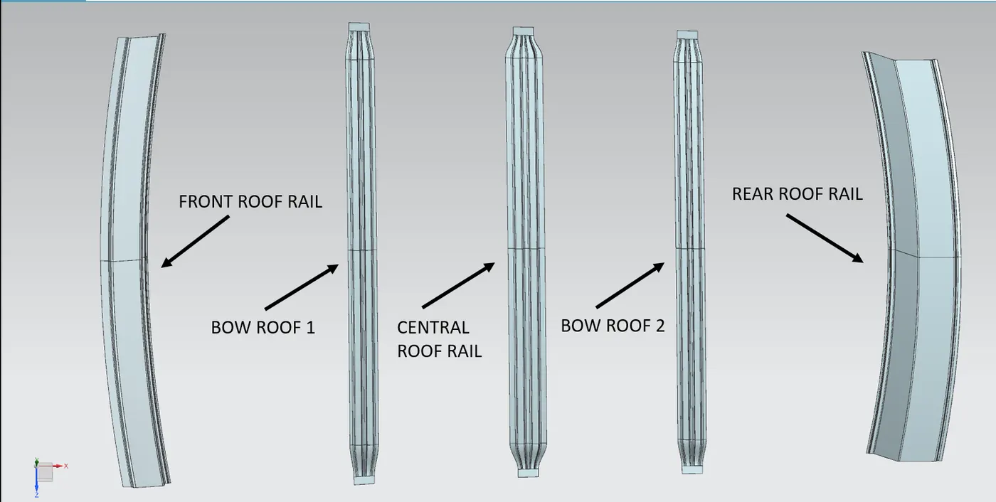
FRONT ROOF RAIL
The front roof rail is a vital structural element positioned along the leading edge of a vehicle's roof. Usually constructed from high-strength materials like steel, it contributes significantly to the vehicle's overall structural integrity and safety. In the event of a collision, the front roof rail serves a critical role by absorbing and dispersing impact forces, thereby safeguarding occupants. Its robust design ensures that it can withstand various loads and pressures, enhancing the vehicle's crashworthiness. Additionally, it provides anchorage points for other safety features and plays a pivotal role in maintaining the vehicle's dimensional stability and occupant protection standards.
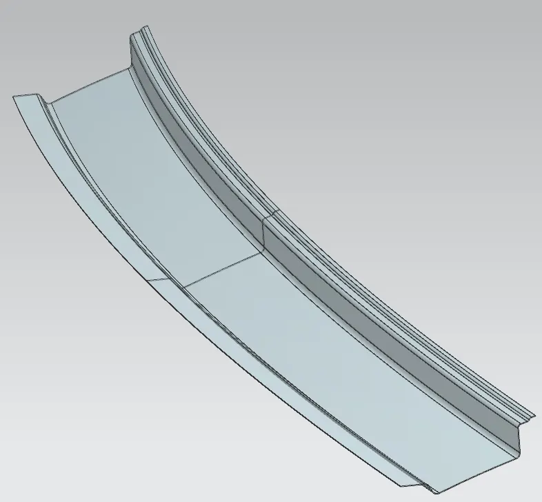
BOW ROOF
It resembles an arched or curved shape, resembling a bow. These bow-like reinforcements are strategically placed within the vehicle's roof structure to enhance its strength and integrity. Bow roof reinforcements serve several essential purposes in car design. Firstly, they contribute to the overall structural rigidity of the vehicle, which is crucial for safety and handling. Secondly, they help distribute impact forces in the event of a collision, thereby enhancing passenger safety. Additionally, bow roof reinforcements may also support the vehicle's roof liner and contribute to noise insulation .Their design and placement are carefully engineered to meet stringent safety standards and crash-test requirements. They play a vital role in ensuring that a car can withstand various types of impacts while safeguarding the occupants within the cabin.
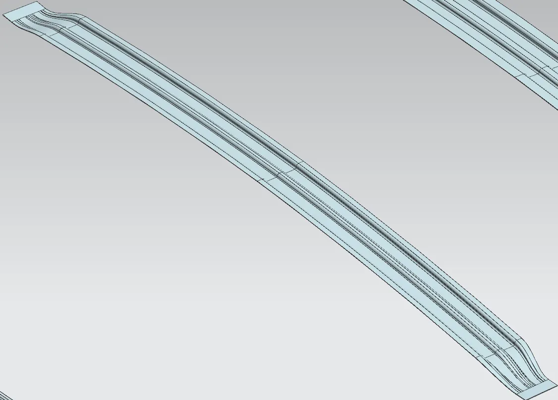
CENTRAL ROOF RAIL
Besides of structural rigidity and distributing the impact forces of a collision, the central roof rail may also have design elements, such as integrated handles or mounting points for accessories like roof racks. These additions make the roof rail both functional and aesthetically pleasing while adhering to safety and design criteria in automotive engineering.
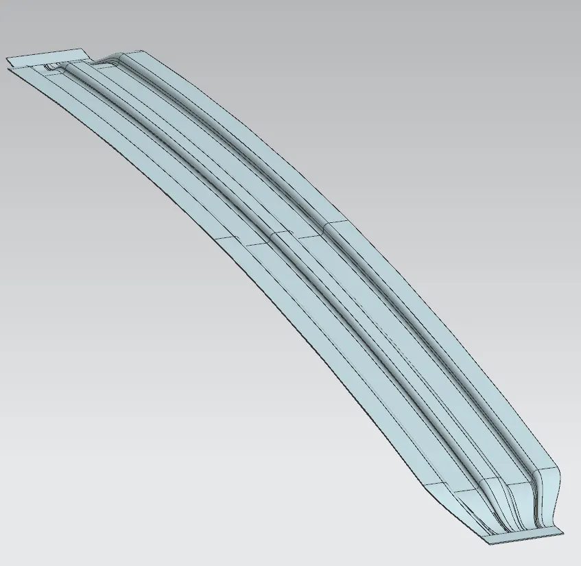
REAR ROOF RAIL
It is a structural component positioned along the back edge of a vehicle's roof. The primary purpose of the rear roof rail is to enhance the vehicle's safety and structural integrity. In the event of a collision or rollover, it helps distribute impact forces, safeguarding the occupants within the car's cabin. Additionally, rear roof rails may serve as anchor points for various accessories, such as roof racks, and they often have design considerations to complement the vehicle's aesthetics while adhering to stringent safety standards in automotive engineering.
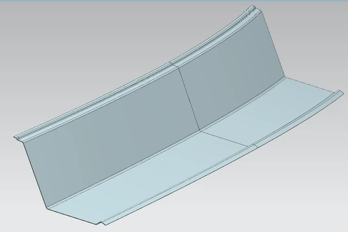
ROOF ASSEMBLY
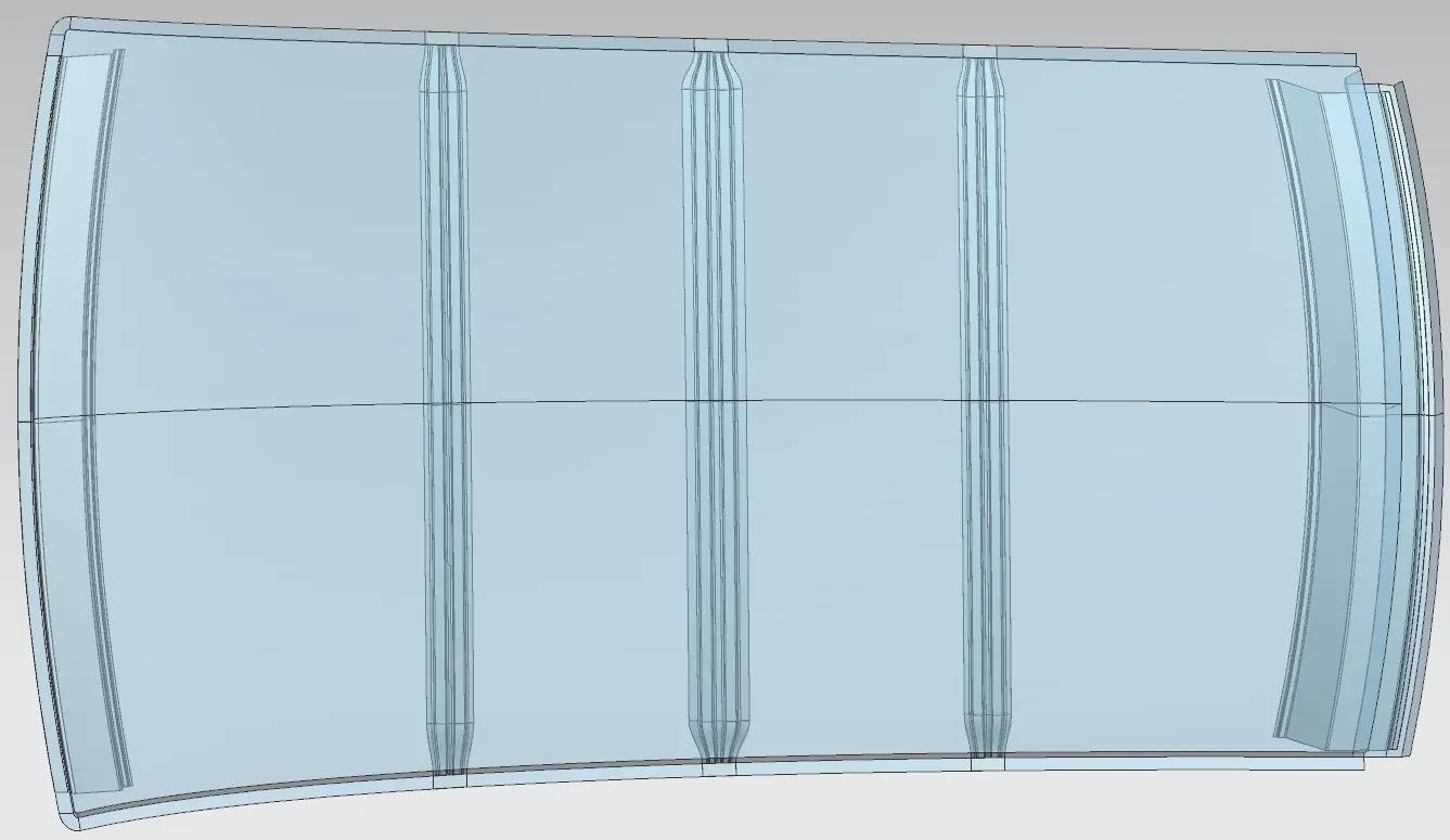
DRAFT ANALYSIS
An analysis was conducted on the designed roof and its associated reinforcements. It was determined that, for the manufacturing of a sheet metal component related to this structure, a minimum draft angle of 7 degrees is necessary. This draft angle is a critical parameter in the manufacturing process, ensuring proper formability and ease of production for the sheet metal component.
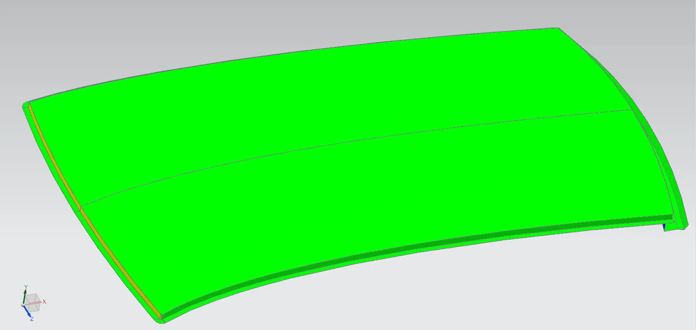
DRAFT ANYSIS ON OUTER ROOF WITH FLANGE
It was observed there is a negative draft at the rear side of the roof , due to the given design cosiderations but it can be cleared out with secondary tooling axis .
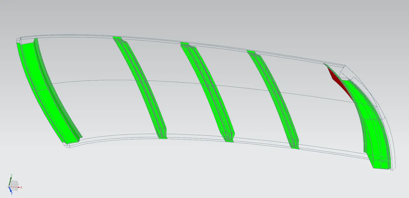
DRAFT ANALYSIS ON REINFORCEMENTS OF THE ROOF
As shown in the picture it was observed all of the reinforcements cleared draft analysis (min draft 7 degrees), so that they have better manufacturability.
HEAT DISTORTION CRITERIA
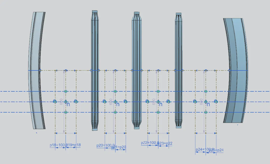
Bow–Roof Prediction Formula
W = [1.73 x 10^(-3) x L] + [1.85 x 10^(-8) x (R^2)/t] + [ 1.10x10^(-3) x l] - 2.68
Where,
L = Roof Length in X-Direction[mm](Roof dimension in 0-Y)
R = Roof curvature
R = 2(Rx*Ry)/(Rx+Ry)
Rx = X curvature
Ry = Y curvature
t = Roof plate thickness [mm]
l = Bow Roof Span [mm]
Judgment Condition
OK< 2>
|
SI:No. |
Bows |
Rx |
Ry |
R |
l |
L |
t |
W |
Result (OK/NG) |
|
1 |
FR & BR1 |
5711.40 |
2873.43 |
2873.43 |
486.99 |
2033.7 |
0.75 |
1.73 |
OK |
|
2 |
BR1 & CTR |
4867.74 |
6617.46 |
5609.31 |
319.83 |
2033.7 |
0.75 |
1.96 |
OK |
|
3 |
CTR & BR2 |
4071.25 |
10109.27 |
5804.77 |
319.63 |
2033.7 |
0.75 |
2.02 |
OK |
|
4 |
BR2 & RR |
3364.25 |
14041.80 |
5428.01 |
447.67 |
2033.7 |
0.75 |
2.05 |
OK |
SNOW LOAD CRITERIA
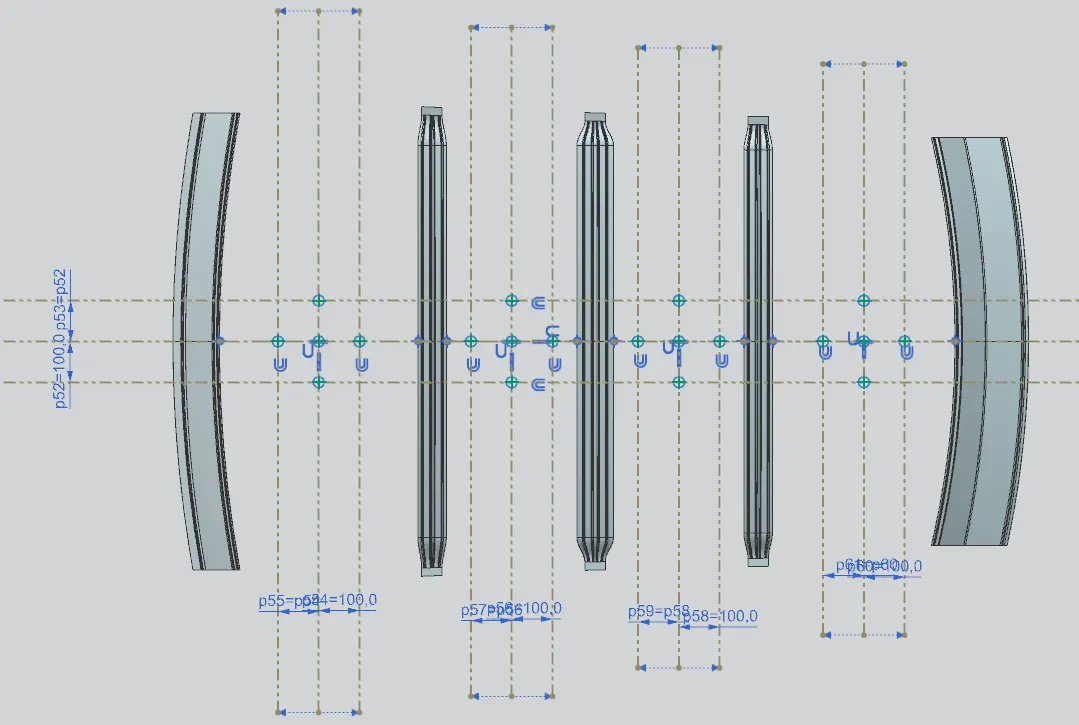
Snow Load Prediction Formula
Qr = [Iy x t2] / [α x s x [(Rx + Ry)/2]2 x 10-8]
Where,
α = My x Lx2 x 10-12 , My = Y(Ly-Y)
t = Roof plate thickness [mm]
Ly = Distance between the front and rear roof Rails on the Vehicle along with 0Y[mm]
Length of Roof panel with the center point between Roof rail Front /Rear as the front and rear reference point.
Lx = Distance between the Left and Right end of the roof on the Roof BOW [mm]
The width of the roof panel is exposed on the surface.
Y = Distance front Front Roof Rail to Roof BOW[mm]
s = Distance for which Roof BOW bears divided load [mm]
s = L1/2 + L2/2
Iy = Geometrical moment of inertia of Roof BOW (Y cross-section )[mm4]
Rx = Lateral direction curvature radius of roof panel Y cross-section on Roof BOW [mm]
Roof panel curvature Radius of the Length Lx in Front view
Ry = Longitudinal Direction curvature radius of the Roof panel X cross-section on Roof BOW [mm]
Roof panel X curvature radius of length s in Side view
Judgment condition
Qr ≥ 3.1
|
S.NO |
BOW |
Iy |
α |
Lx |
Ly |
Y |
S |
Rx |
Ry |
t |
Qr |
OK/NG |
|
1 |
FR to BR1 |
399.35 |
1.0 |
1134.08 |
1932.97 |
573.11 |
486.27 |
4341.07 |
2898.31 |
0.75 |
3.51 |
OK |
|
2 |
BR1 to CTR |
807.20 |
0.72 |
1086.66 |
1932.97 |
399.44 |
399.50 |
3789.92 |
6545.02 |
0.75 |
5.88 |
OK |
|
3 |
CTR to BR2 |
400.67 |
0.69 |
1063.93 |
1932.97 |
399.56 |
480.20 |
4227.97 |
10506.69 |
0.75 |
1.24 |
NG |
|
4 |
BR2 to RR |
- |
0.84 |
1048.83 |
1932.97 |
560.85 |
280.42 |
4127.29 |
15634.04 |
0.75 |
- |
- |