Roof Design
Objective:
The main objective of this challenge is for the Given Roof styling, create an ASSEMBLY by developing the essential flanges for the outer roof and creating the reinforcements.
Introduction
An automobile roof or car top is the portion of an automobile that sits above the passenger compartment, protecting the vehicle occupants from sun, wind, rain, and other external elements. Because the earliest automobiles were designed in an era of horse-drawn carriages, early automobile roofs used similar materials and designs.
Types of Car roofs
• Convertible roofs
• Hardtops
• Sunroofs
• T-tops
• Targa tops
• Vinyl roofs
Safety point of view vehicle roof plays a very crucial role especially roll over kind of accidents, in which vehicle tips over onto its side of the roof. And vehicle rollover crashes are the causes of many fatalities and several heads, neck, and spine trauma around the world. Therefore, passenger safety is also a very important parameter in front of OEMs. It is not only a marketing strategy but also it is an obligation stipulated by international standards that are now placed in several countries, as well as a governmental requirement. Rollover crashes, especially in the country, are usually very destructive events. Vehicle damage often includes the deformation of the roof and its supporting structures. Head and neck injuries are common and associated with roof deformation. Strengthening of the roof is suggested as an appropriate countermeasure for such injuries.
Types of Rollovers
1. Tripped-NHTSA data show that 95% of single-vehicle rollovers are tripped. This happens when a vehicle leaves the roadway and slides sideways, digging its tires into soft soil or striking an object such as a curb or guardrail.
The high tripping force applied to the tires in these situations can cause the vehicle to roll over. E.g. Soft soil, Guardrail, Steep Slope
2. Un-Tripped -On-tripped rollovers are less common than tripped rollovers, occurring less than 5% of the time, and mostly in top-heavy vehicles. Instead of an object serving as a tripping mechanism, un-tripped rollovers usually occur during high-speed collision avoidance maneuvers.
Inputs Given From Styling Team
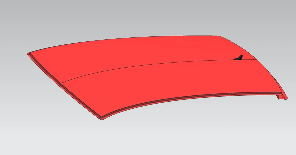
1. A surface with a railing Rack
We want to improve the given roof for the smoother surface by giving fillets on the sharp area and make the roof for the better design approach to the new design, it shown below
Front Roof Rail
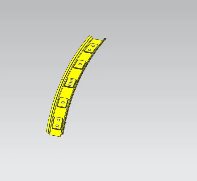
It is the support that is joined the windshield glass. Body side outer and the inner panels. Its thickness is usually 0.75mm. The windshield end flanges are the extract offset of the roof surface. The bottom-most flanges is decided after taking into consideration the visibility criteria. Spot weld is applied at the windshield end of the other end is joined with the roof using Mastics sealants which also contributes to increases strength.
For designing the front roof rail we need to consider some parameters which are as discussed below
a. Visibility of the driver and passenger
We always keep in mind while designing the front roof we do not reduce the visibility available to the driver. While designing a front roof one must stick to the master section dimensions because little change in dimension will have an impact on the visibility of the driver (e.g. small change in angular dimension will lead to a large change in linear dimension)
Front Roof Rail Master section
By using the above master section we'll create the front roof rail,
Rear roof rail
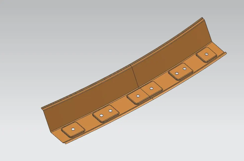
It is the support that is joined to the back door and the Body side outer and the inner panels. it is usually made from body side outer scrap and therefore the thickness of the rail is 0.75mm. Similar to the Front roof rail design. We have to take into consideration the rear headroom clearance and the rear visibility criteria while designing the rear roof rail from the backdoor design and also taken into consideration od the required clearance. Spot welds are applied at the back door end of the rail and the other end is joined with the roof using Mastic sealants.
Master section of the Rear Roof Rail
Bow Roof Rails
Similar to the other design, we have to take into consideration of the headroom clearance and the visibility criteria while designing the centre roof rail and bow roof rail. Here spot weld is not applied for joining these rails of the roofs. Instead mastic sealants are used are introduced at both ends since centre Roofs are fully positioned under the styling surface of the roof. For increasing the strength of the rails, Embossing is done. To reduce the weight of the material used, different styling has been followed with a thickness of 0.75mm.
Master section of Bow Roof
Here I'm using two Bow roofs, they are,
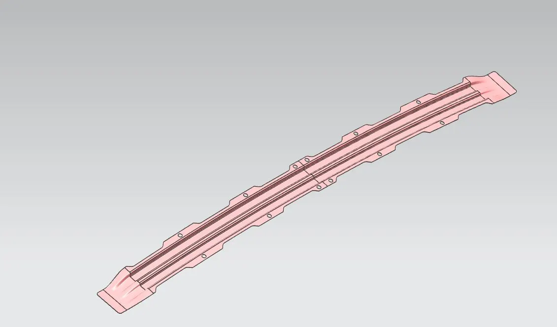
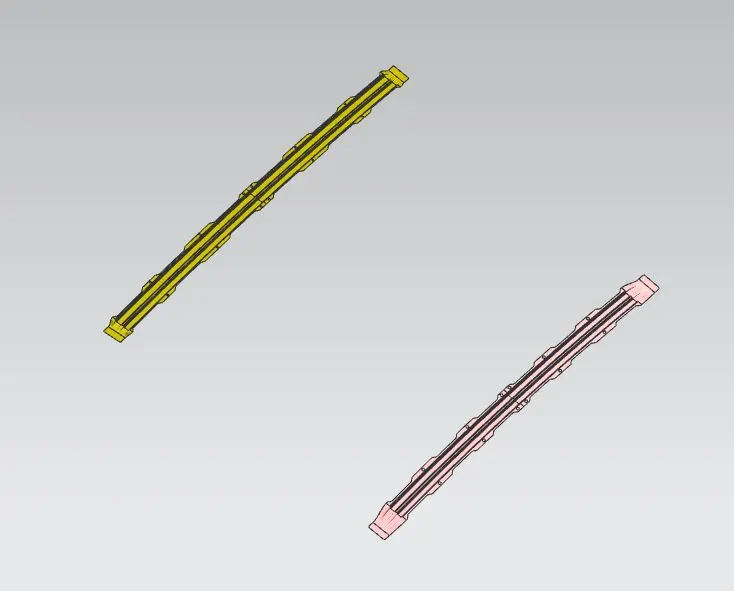
Reinforcement centre rail
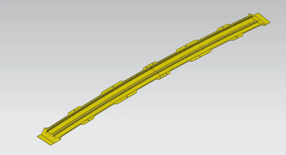
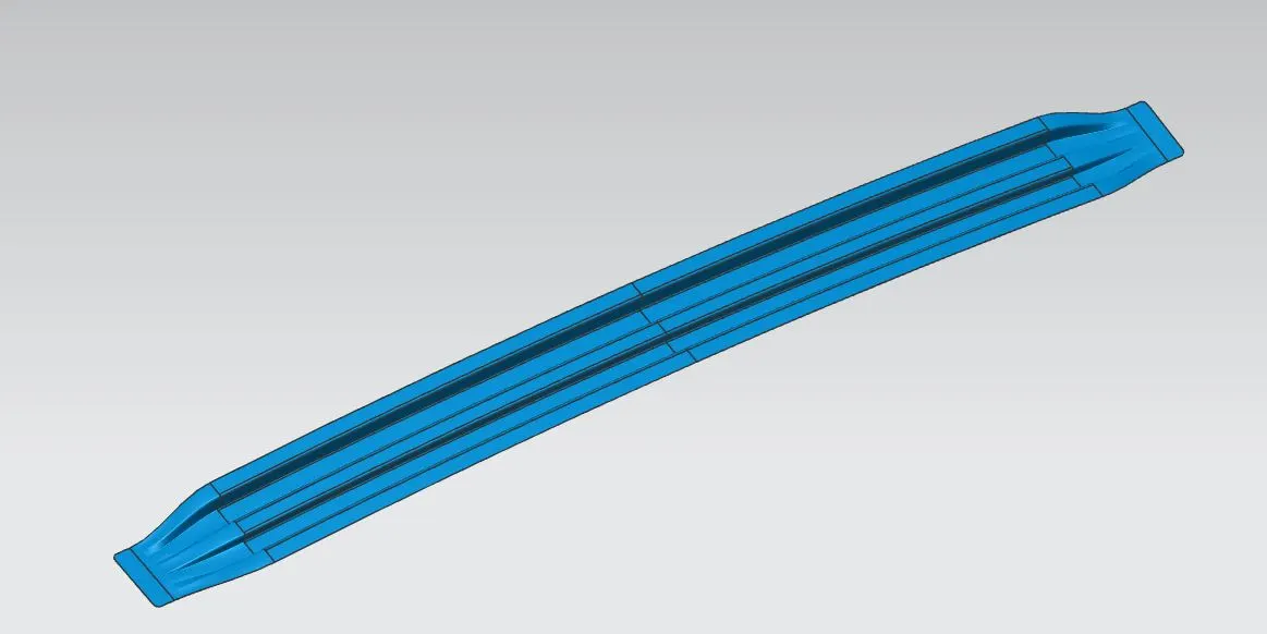
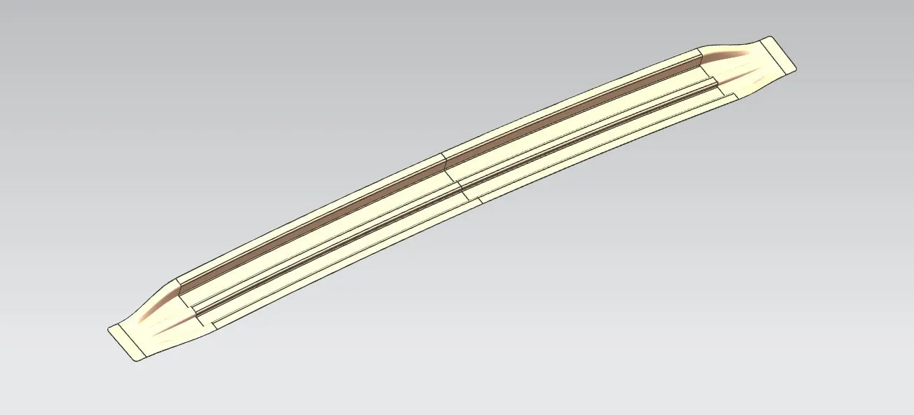
It is the main supporting rod for the roof. Their purpose is to provide an attachment point for crossbars and other devices designed to secure loads carried on the roof of the vehicle, it absorbs energy at the time of the crash. Its thickness is 0.75mm. Here we are using two Reinforcement roof.
Master section of Center Reinforcement Rail
Center Roof :
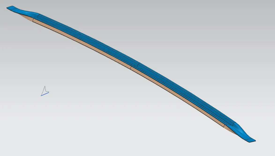
After creating all the parts for the roof on the car we'll do the analysis on it.
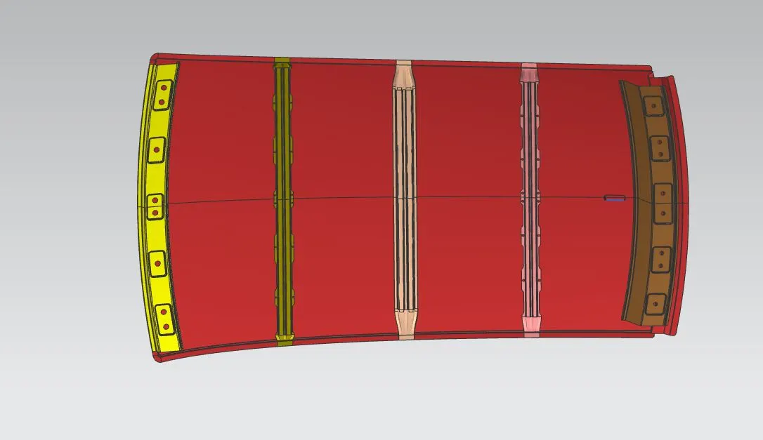
Draft analysis:
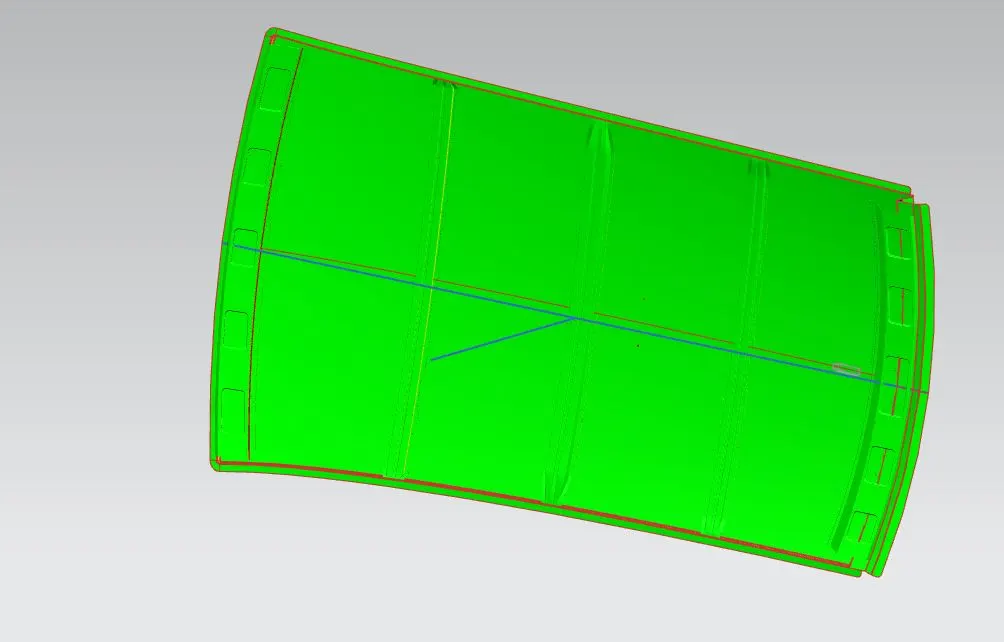
For doing the draft analysis we'll create one line which is for the tooling axis ini the required vector direction.
Roof:
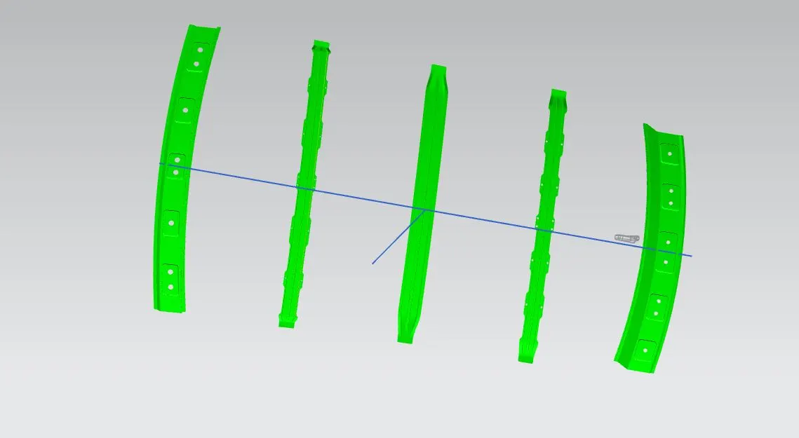
Rail Roofs:
Curvature Analysis:
It is done to justify the positioning of the bow roofs. There are mainly two criteria to fulfill
- 1.Heat distortion criteria
- 2.Snow load criteria
Heat Distortion Criteria:
Introduction
Heat distortion temperature is the temperature at which the metal softens and deforms under a specific load.
This study is done to check the ability of the roof to withstand high temperature with respect to the positioning of the reinforcements which contribute to increased strength.
Why Heat Distortion Criteria?
- The use of high-tensile steel sheets on car bodies has increased, and the weight of bodies has decreased, for enhance fuel economy.
- by fabricating pieces from thinner sheets. The surface areas of outer panels such as a roof panel and door outers are large, so the effects of weight reduction are also large and thereby the needs for thinner panels are high.
- Some studies have noted issues with the outside quality where, when thinner outer panels are employed, the surfaces of shells bend owing to thermal strain during the painting and drying processes in addition to issues with the stamping performance (hence, referred to as thermal distortion).
- The washing, electrodeposition, sealing, and finish coating steps are all included in the painting of a vehicle's body. An automobile body is submerged in an electrocoating solution during the electrodeposition process to create an electrodeposited film.
- The body is then put through the drying process, where hot air from a furnace is used to dry the electrocoating solution. If thermal distortion is discovered, it requires a significant amount of labour -hours for reworking and checks for numerous parts and across multiple manufacturing processes.
- Thermal distortion is frequently evaluated by the exterior check conducted for completed vehicles with various parts installed.
- Countries where the summer is high, there are chances of heat distortion due to sun heat. When the radiation of sun falls on the form of your car, then due to that heat, thermal expansion occurs and due to some thermal expansion, possibility of hanging the roof of the car is more in that area and the roof of your car becomes weak in that area.
- By this calculation we verify these things whether your roof will be able to withstand in that condition or not?
- If so that the area is not able to tolerate this condition then we have to give better support on that area to make your roof stronger.
Bow–Roof Prediction Formula
W = [1.73 x 10^(-3) x L] + [1.85 x 10^(-8) x (R^2)/t] + [ 1.10x10^(-3) x l] - 2.68
Where,
L = Roof Length in X-Direction[mm](Roof dimension in 0-Y)
R = Roof curvature
R = 2(Rx*Ry)/(Rx+Ry)
Rx = X curvature
Ry = Y curvature
t = Roof plate thickness [mm]
l = Bow Roof Span [mm]
Judgment Condition
OK< 2>
For calculating these we want to calculate the variable by using the sketches to create on the roof area and then project it on the surface to get the values,
0-Y which will be the centre line of your roof, from that line you have to create an offset of 300mm which will be your 3-Y, Then 3-Y has to be offset 100mm- 100 mm respectively into up and down direction.
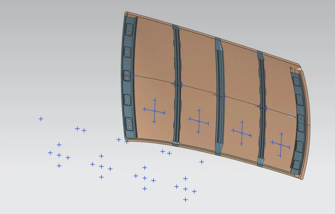
After projecting it on the roof surface and then we can use the 3 point arcs to create the arc on it and then use them to predict the Rx and Ry value.
Finally we'll get this value,

SNOW LOAD PREDICTION
- Snow Load Criteria study is done to check the withstand ability when the snow loads over the roof during winter in snow fall regions. This study will also analyse the roof that whether the permanent deformation occurs after removing the snow load. That it may bend but needs to be bounce back to its original position.
- roof design must pass through these calculations to ensure that it has sufficient stiffness to withstand the load due to accumulation of snow over the roof.
Similar steps you have to repeat to find your R-x and R-y for snow load calculation but you have to do all these operations with zero 0-Y line.
- First of all, we have to create a plane on which we will do all the sketches and that plane should be parallel from your roof outer surface.
Snow Load Prediction Formula
Qr = [Iy x t2] / [α x s x [(Rx + Ry)/2]2 x 10-8]
Note: The Qr value given over here is correct. There was a typo error in the formula given in the video.
Where,
α = My x Lx2 x 10-12 , My = Y(Ly-Y)
t = Roof plate thickness [mm]
Ly = Distance between the front and rear roof Rails on the Vehicle along with 0Y[mm]
Length of Roof panel with the center point between Roof rail Front /Rear as the front and rear reference point.
Lx = Distance between the Left and Right end of the roof on the Roof BOW [mm]
The width of the roof panel is exposed on the surface.
Y = Distance front Front Roof Rail to Roof BOW[mm]
s = Distance for which Roof BOW bears divided load [mm]
s = L1/2 + L2/2
Iy = Geometrical moment of inertia of Roof BOW (Y cross-section )[mm4]
Rx = Lateral direction curvature radius of roof panel Y cross-section on Roof BOW [mm]
Roof panel curvature Radius of the Length Lx in Front view
Ry = Longitudinal Direction curvature radius of the Roof panel X cross-section on Roof BOW [mm]
Roof panel X curvature radius of length s in Side view
Judgment condition
Qr ≥ 3.1
250 ≤ s ≤ 380
For calculating these we want to calculate the variable by using the sketches to create on the roof area and then project it on the surface to get the values,
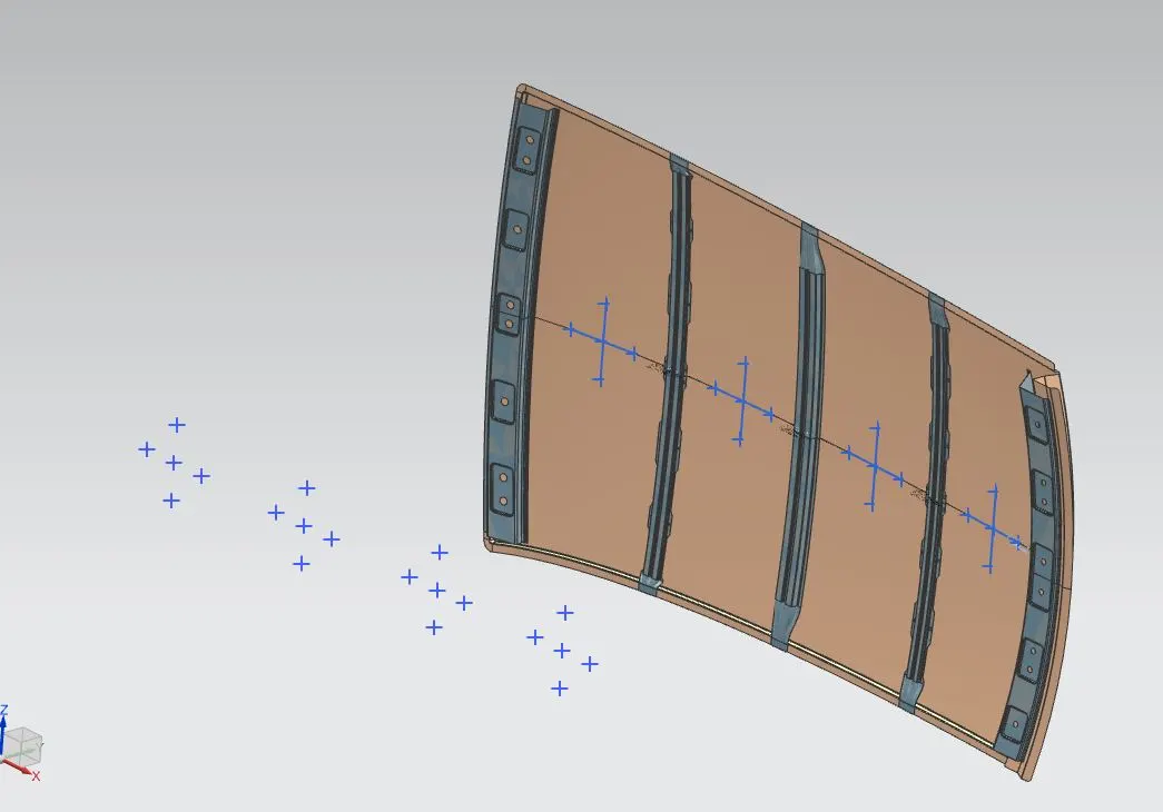
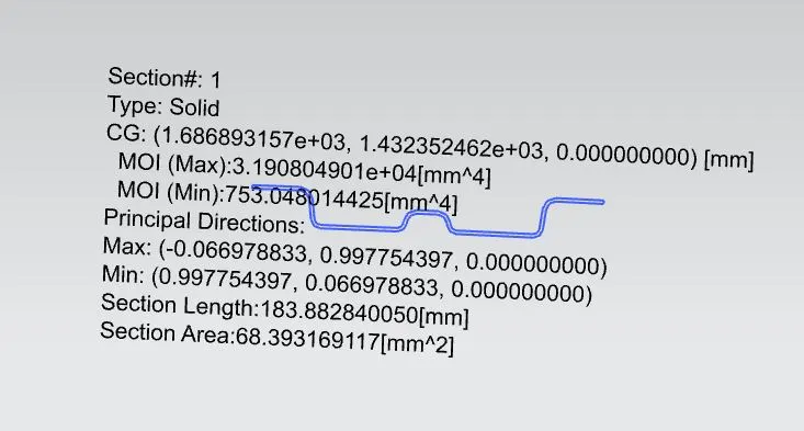
These are used to calculate the Rx and Ry values, and then we'll use the section modulus to find the moment of inertia,
Bow roof -1:
Center Reinforcement Roof:
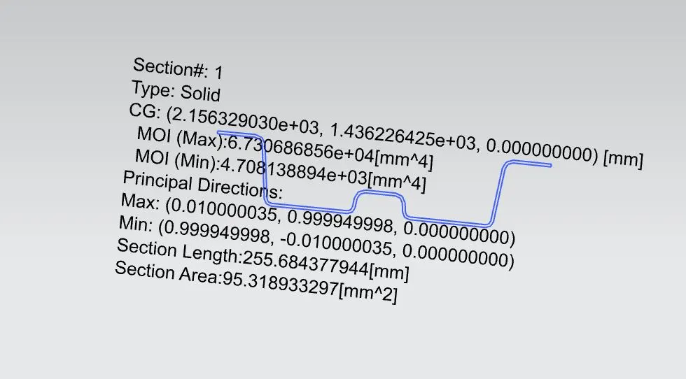
Bow Roof - 2:
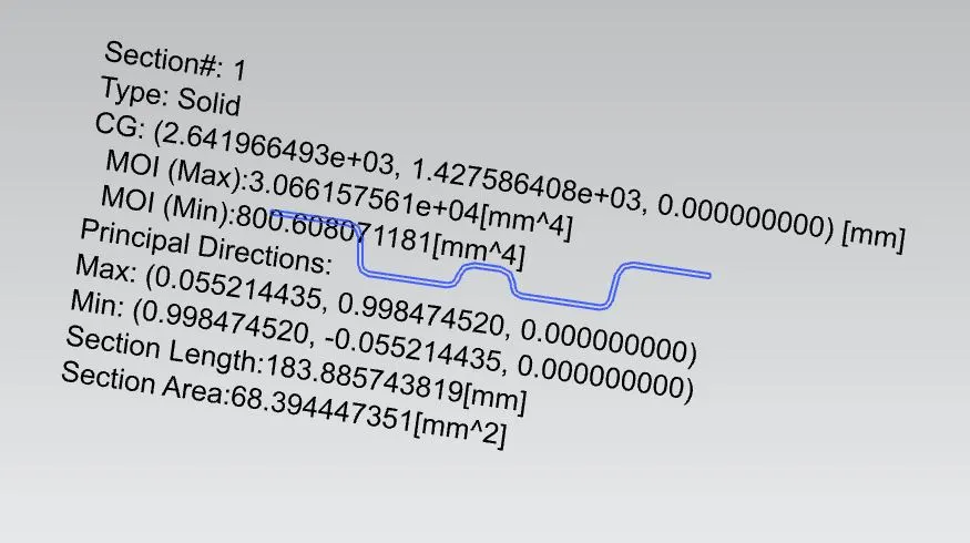
After getting all the values we'll do the calculations and getting the final output as,

Final Roof Design Assembly:
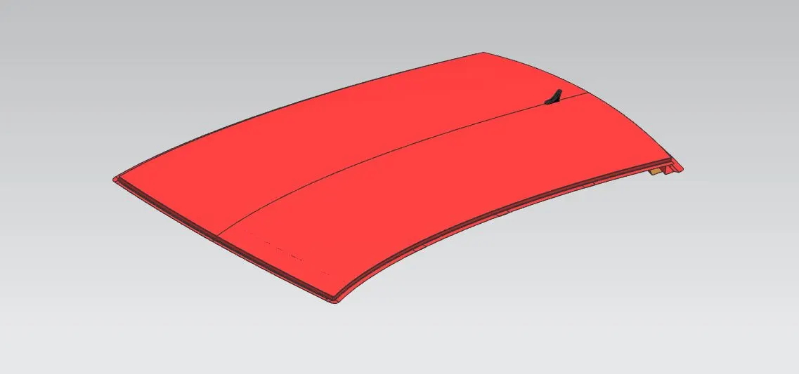
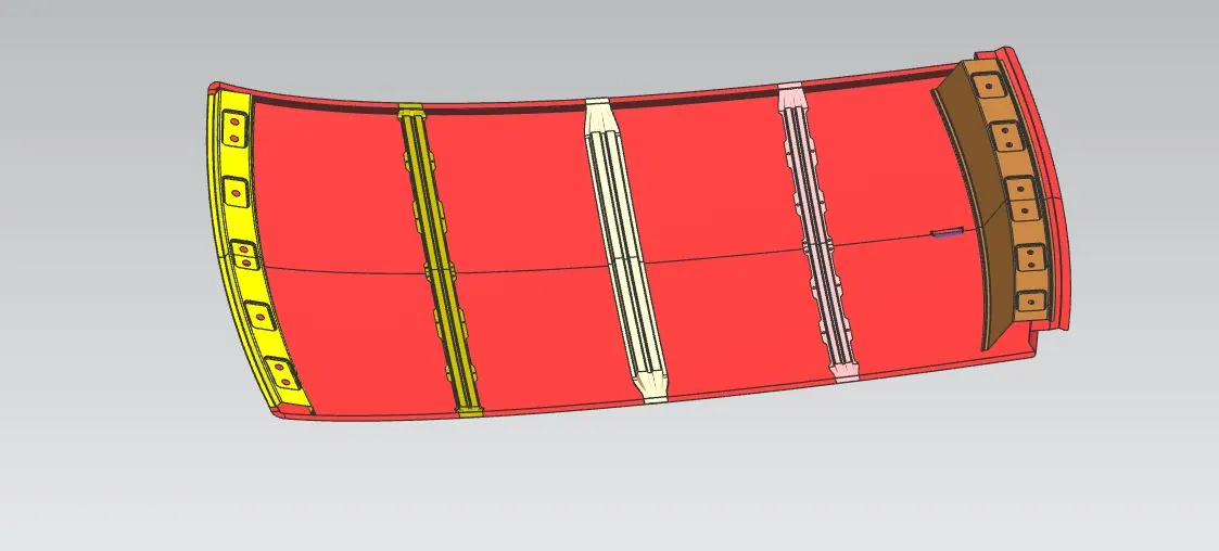
Conclusion-
1. Using all input data we have successfully designed Ditch area flanges, Front roof rail, Bow roof rails 1&2, Rear roof
rail as per the requirement
2. As per heat distortion criteria we come to know all bow roof positions are OK
3. As per Snow load criteria we come to know there is improvement required so we forward this data to our styling colleague to improve and do changes on A surface.
4. All roof rails draft analyses are found OK