Roof Design
Roof Design
OBJECTIVE:
- Study the curvature of the roof class A surface.
- Create the flanges of the roof wrt the master section.
- Create the front and rear roof rails following the master section.
- Create the bow roofs by understanding the curvature of the roof.
- Create the center roof rail along with the reinforcement.
- Perform the heat distortion and snow load study to rectify the positioning of all roof rails.
- Performing the Draft analysis.
ROOF
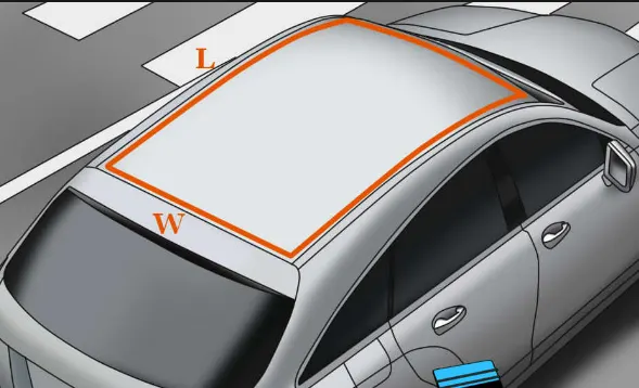
The section of an automobile that sits above the passenger compartment serves the purpose of shielding the vehicle's occupants from the sun, wind, rain, and other external factors. This section is also known as the car roof. The roofs of the earliest automobiles utilized similar materials and designs because they were constructed during the same period as horse-drawn carriages.
By installing appropriate roof rails, the roof also protects the passengers from obstacles or collisions.
TYPES OF CAR ROOF
1) CONVERTIBLE ROOF
A convertible is a traveller vehicle that can be driven regardless of a rooftop set-up. The different models have different ways to store and retract the roof. A convertible permits an outside driving encounter, with the capacity to give a rooftop when required. The reduced structural rigidity of convertibles is one potential drawback. to mitigate the effects of removing a car's roof, requiring significant engineering and modification
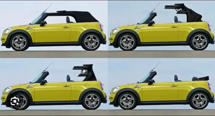
The majority of convertible roofs have a framework that folds down, and the actual roof is made of cloth or another fabric. Retractable hardtops (often made of metal or plastic) and detachable hardtops (where a metal or plastic roof is manually removed and frequently stored in the trunk) are two other types of convertible roofs.
2) SUNROOF
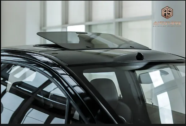
A sunroof is a movable panel that opens to reveal a window in the roof of a car. This lets light and fresh air into the passenger room. Sunroofs come in a variety of shapes, sizes, and designs and can be operated manually or by a motor. While the term sunroof is currently utilized conventionally to portray any glass board on the rooftop, the expression "moonroof" was generally used to depict fixed glass sheets unbendingly mounted in the rooftop board over the traveller compartment. A transparent and frequently tinted glass panel makes up a moonroof. Past terms incorporate Daylight Rooftop, Sliding Head and Sliding Rooftop.
3)HARDTOP
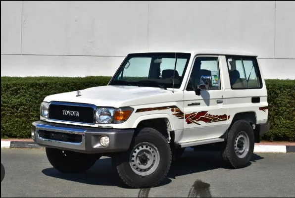
A hardtop is a rigid automobile roof, typically made of metal in modern automobiles. A hardtop roof can be fixed (not removable), detachable for separate storage, or retractable inside the vehicle.
The pillars hardtop, or simply "hardtop," is a body style for cars without a B-pillar that is frequently styled to look like a convertible design.
ROOF DITCH AREA AND FLANGES:
The roof ditch area and flanges are created about visibility criteria, safe head distance, headliner and various other factors which govern the size of the roof rails and also which are related or connected to the roof like a windshield.
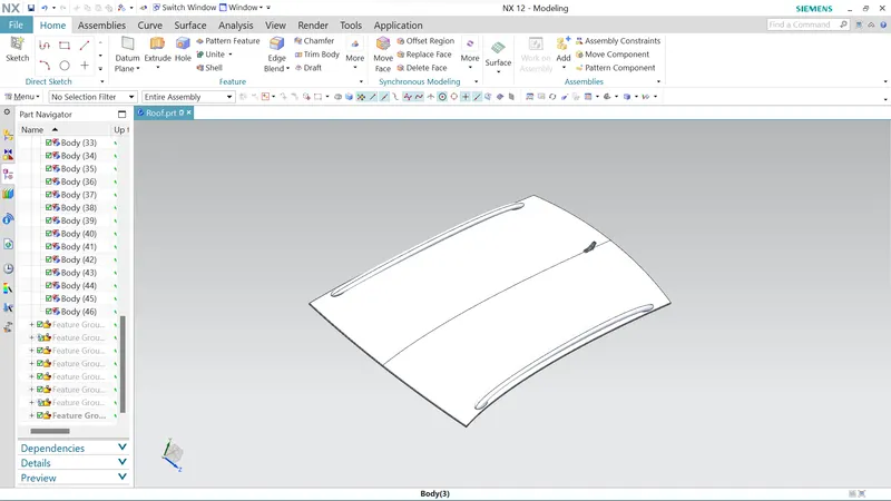
design consideration of roof:
1. Visibility criteria.
2. headroom clearance
3. Curvature study
4. heat distortion and snow load criteria
5. draft analysis
6. Safety parameters
Roof crush test :
From a safety point, the roof of a vehicle plays a crucial role, particularly in rollover accidents, in which a vehicle tips over onto its side roof. Additionally, vehicle rollover accidents account for numerous fatalities and injuries to the head, neck, and spine worldwide. As a result, OEMs place a high value on passenger safety as well. It isn't just a promoting technique yet in addition it is a commitment specified by global norms that are presently placed in a few nations, as well as a legislative prerequisite.
Rollover accidents typically cause a lot of damage, especially in rural areas. Deformation of the roof and its supporting structures is a common result of vehicle damage. Roof deformation is linked to a lot of head and neck injuries. In the event of such injuries, it is suggested that the roof be strengthened.
Types of Rollovers
- TRIPPED-95% of single-vehicle rollovers are tripped, according to NHTSA data. This occurs when a vehicle leaves the roadway and slides sideways, either striking a curb or guardrail or digging its tires into the soft soil. The vehicle may tip over as a result of the high tripping force applied to the tires in these circumstances. Soft soil, guardrail, and steep slope are examples.
- UNTRIPPED-Untripped: Untripped rollovers are less common than tripped rollovers, affecting most top-heavy vehicles less than 5% of the time. Untripped rollovers typically occur during high-speed collision avoidance manoeuvres rather than a tripping object.
Thus, strength is a vital rule for planning vehicle rooftops. The driver's or passenger's side of the test vehicle is chosen for testing after it has been acquired. The test site is selected at random for the majority of vehicles. In any case, for rooftop plans that seem deviated, designing judgment is utilized to choose the side of the rooftop that might bring about a lower top
force
Testing position according to standards:
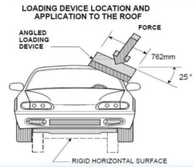
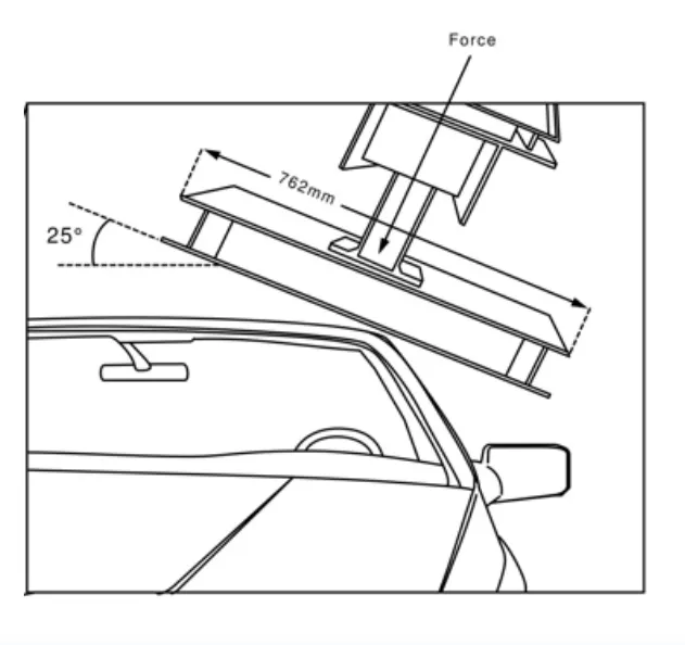
With the vehicle on a level surface, the on-street pitch point at the front entryway ledge is estimated on the two sides of the vehicle. Roof racks and other non-structural items that might come into contact during the test are left as they were when the vehicle was installed unless the manufacturer requests otherwise. If any trim or other parts get in the way of supporting the vehicle along its rocker panels, they are taken out. The vehicle support system consists of one I-beam (HR A-36, W4X13) for each rocker panel on vehicles with vertical pinch weld flanges on the bottom of the rocker panels. Figures 1 and 2 show that each I-beam has a clamping system built into the top that is secured in place by pressing against the pinch weld flange.
More than one I-beam can be used on each side of the vehicle when the pinch weld flange has a bend that makes it impossible to support the sill with just one I-beam. For vehicles with no squeeze weld rib, or with a nonvertical rib point that blocks clipping, mounting by another technique might be fundamental, for example, that depicted in the Public Thruway Traffic Security Organization's Research Center Test Method (2006). Preceding testing, the unparalleled view back as an afterthought being tried is leaned back to forestall connection with the devastating rooftop. Latches hold the rear seats in an upright position. Doors are locked and all windows are locked.
TESTING :
A quasi-static test system made by MGA Research Corporation is used for roof strength testing. The system consists of an upright assembly and a loading head that can be fixed at different heights from the ground and at pitch angles ranging from 5 to +5 degrees to accommodate testing on either the driver's or passenger's side. The roll point is for all time fixed at 25 degrees. The platen's movement is controlled by four hydraulic actuators along two linear guides. The entire system is anchored to the floor of the test facility by a T-slot bed plate.
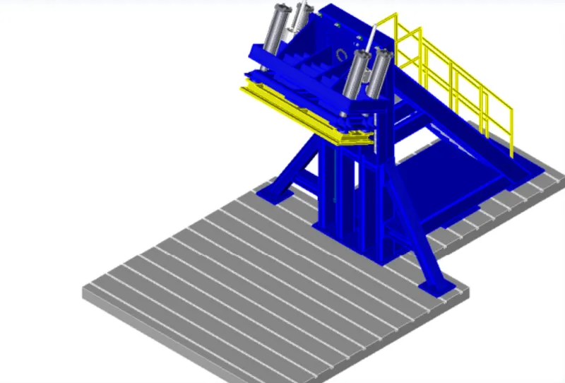
MGA Roof Crush Test System
On the bed plate, perpendicular to the platen's longitudinal axis, are two HR A-36 W10x88 I-beams. The vehicle, with the connected rocker board emotionally supportive network, is put on these shafts.
The vehicle is adjusted so that:
- The longitudinal centerline of the platen is within 10 mm of the underlying rooftop contact point.
- The yaw point of the vehicle compared with the longitudinal pivot of the platen is 0 ± 0.5 degrees.
- The midpoint of the platen's forward edge is 254 ± 10 mm past the most forward place of the rooftop (counting the windshield trim if it covers the rooftop) lying on the vehicle's longitudinal centerline.
To minimize the potential for loading the edge of the platen during the test, there should be a minimum clearance of 150 mm between every point along the forward edge of the platen and the structurally significant body components, when measured normally to the platen’s face
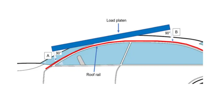
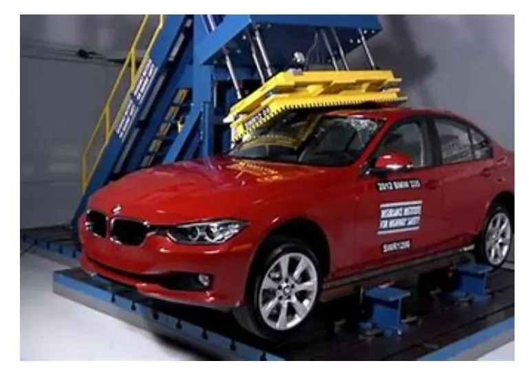
Vehicle Position at the Initial Contact Point
4. The pitch angle of the vehicle matches the on-road angle, while also accounting for any difference between the platen’s pitch angle and the nominal −5 degrees.
components of the roof:
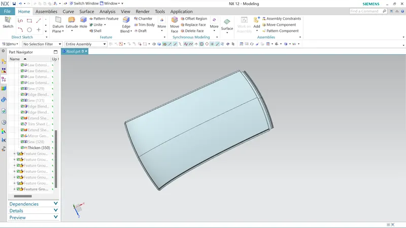
1. Outer roof panel
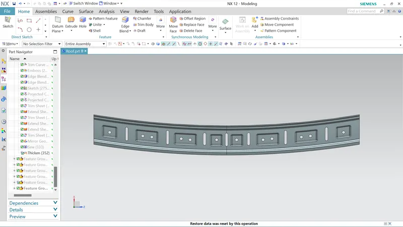
2. front roof rail
3. bow roof rail 1
4. center roof rail
5. bow roof rail 2
6. rear roof rail
Outer roof rail:
Front roof rail:
Bow roof rail :
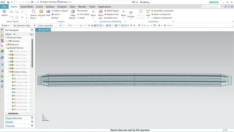
center roof rail:
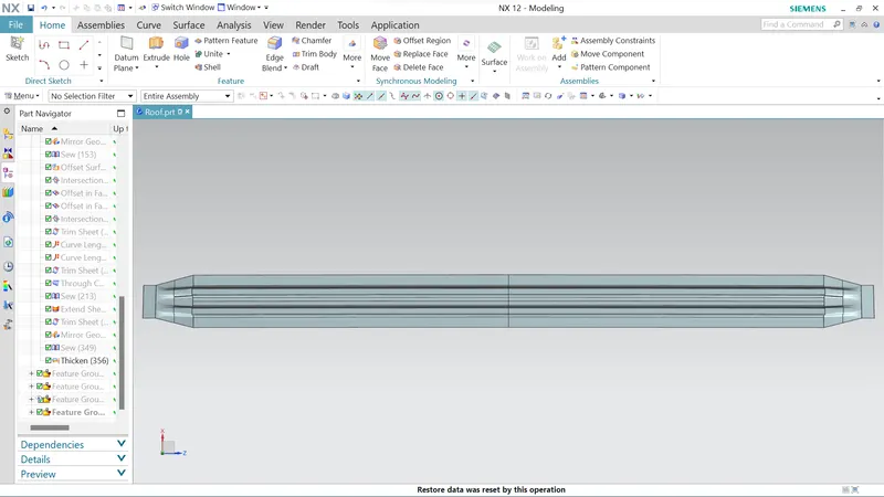
bow roof rail 2:
rear roof rail :
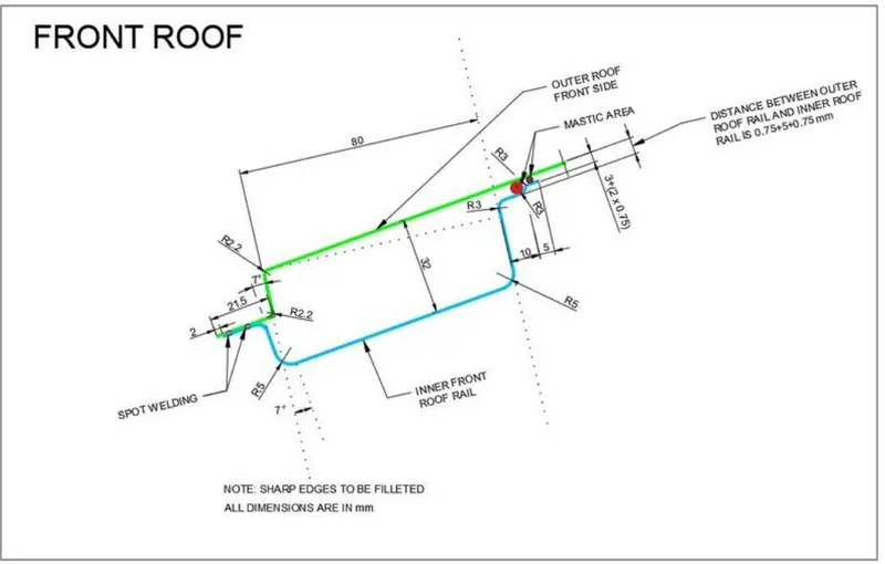
Master sections are given for the reinforcements given above:
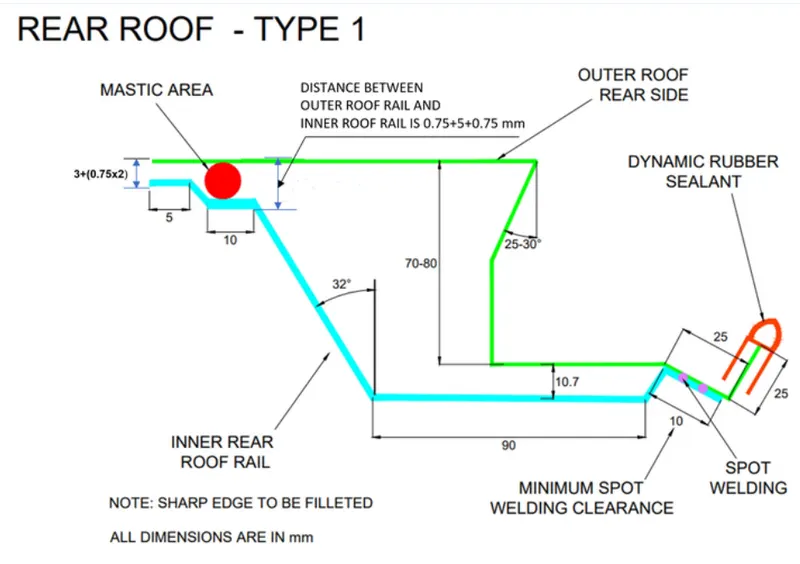
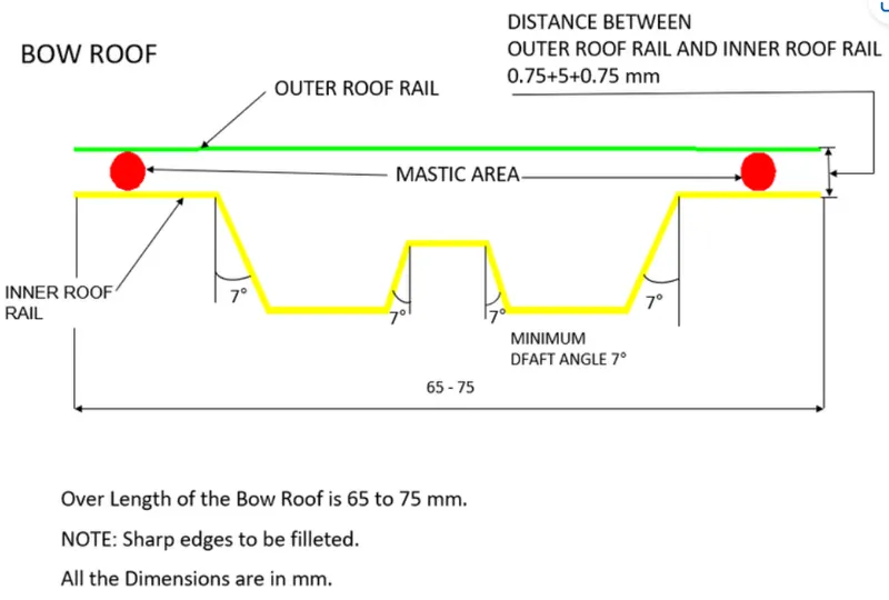
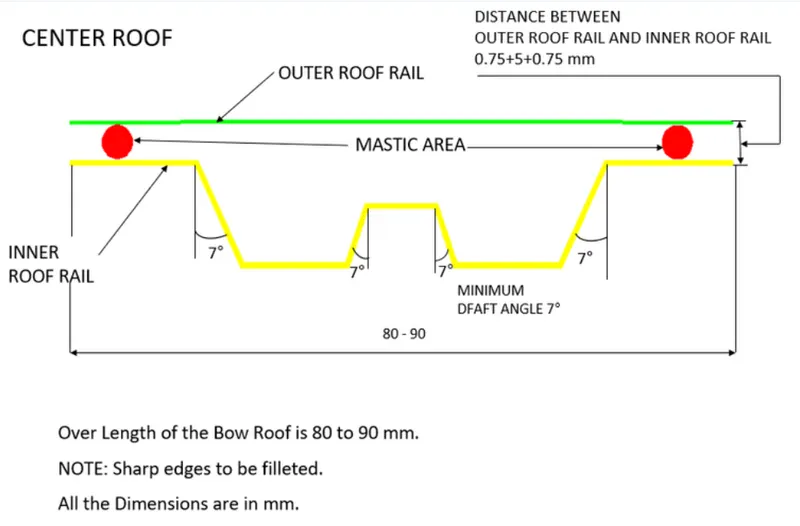
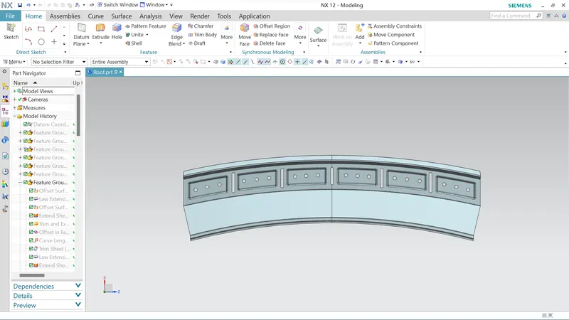
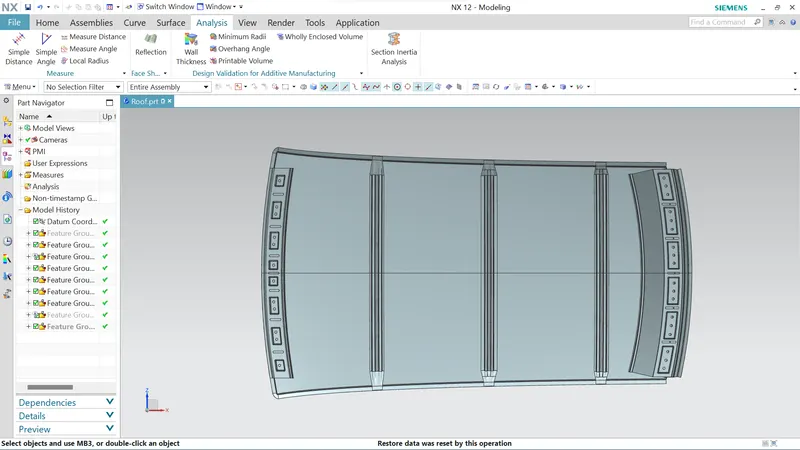
FINAL VIEW
DESIGN CALCULATION OF ROOF:
To ensure the rooftop configuration finishes the examination assessment a portion of the standards is to be viewed as before the plan of bow rails under the rooftop.
they are,
1. Heated distortion study on the roof
2. Snow load condition
HEAT DISTORTION CRITERIA:
Heat distortion temperature is the temperature at which metal softens and deforms under a specified load. These criteria are taken into consideration when designing the roof. When the roof is long and flat, we make bow roofs to make it stronger.
Curvature analysis is used to justify the bow roofs' location.
Bow–Roof Prediction Formula :
W = [1.73 x 10^(-3) x L] + [1.85 x 10^(-8) x (R^2)/t] + [ 1.10x10^(-3) x l] - 2.68
Judgement Condition: OK< 2.7> 3.1
Where,
L = Roof Length in X-Direction[mm](Roof dimension in 0-Y)
R = Roof curvature
R = 2(Rx*Ry)/(Rx+Ry)
Rx = X curvature
Ry = Y curvature
t = Roof plate thickness [mm]
l = Bow Roof Span [mm]
| BOW POSITION | Rx | Ry | R | I | L | W | OK/NOT | |
|
5732.2 | 1905.01 | 1429.82 | 421.36 | 2119.5 | 1.5 | OK | |
|
3553.88 | 4468.14 | 1979.48 | 479.33 | 2119.5 | 1.61 | OK | |
|
2423.88 | 6177.13 | 1740.8 | 479.33 | 2119.5 | 1.58 | OK |
Judgment Condition
W< 2.7
SNOW LOAD PREDICTION FORMULA:
The weight of accumulated snow and ice exerts a downward force on a car's roof, known as snow load. If the snow load is greater than the roof was designed to support, the roof may fail. Or, if the roof was poorly constructed or designed.
- To calculate the snow load condition, we have a snow load formula
- To measure the required values
- Created a sketch and draw a line on the OY axis from the center of the roof
- From that line draw a parallel line distance of 100mm on both sides
- Then make intersection points of these lines and draw a three-point arc
Therefore, there is a formula for predicting the roof's strength.
Qr = [Iy x t2] / [α x s x [(Rx + Ry)/2]2 x 10-8]
Where, α = My * Lx2 * 10-12 , My = Y (Ly – Y)
t: Roof plate thickness (mm).
Ly: Distance between FRR and RRR at 0Y (mm).
Lx: Distance between Left and Right end of the roof (Width) (mm).
Y: Distance Between FRR centre and BOW centre (mm).
s: Distance for which roof Bow bears divided load (mm)
s = (L1 / 2)+ (L2 / 2).
Ln = Centre to centre distance between consecutive Bows.
Iy: Geometric moment of inertia of roof BOW (Y Section) (mm4).
Rx: X Curvature.
Ry: Y Curvature.

Judgment condition
Qr ≥ 3.1
250 ≤ s ≤ 380
Now that we have these values for the snow load, the condition is not met.
Therefore, to strengthen the roof, we make embosses on it.
DRAFT ANALYSIS
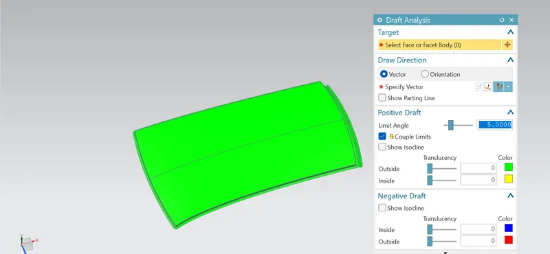
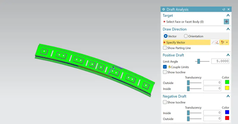
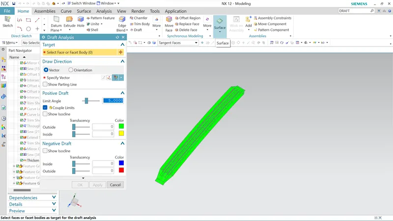
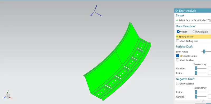
The designed features meet the "green" minimum draft angle.
CONCLUSION:
As a result, the design and development of the roof's ditch area and the necessary reinforcement were based on the provided styling.
The roof's curvature was examined using heat distortion and snow load standards.
The draft investigation was finished to check the toolablilty.