Roof Design Using siemens NX
A Report on Roof Design
Aim- To study Design and analysie the Roof
Objective - 1.To study parts of roof
2. To Study manufactureing process for roof
3. To Design Roof by following standard considerations
4 . To Analys the roof curvature and draft of the Roof
Theory -
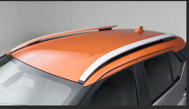
Sheet metal of 0.75 mm is used as a raw material which is followed by Stamping process to give desired shape to it
.
.
Components of Roof
1. outer roof
2.front roof rail
3.Bow roof 1
4. Centre bow roof
5. Bow roof 2
6.Rear roof rail
1. OUTER ROOF
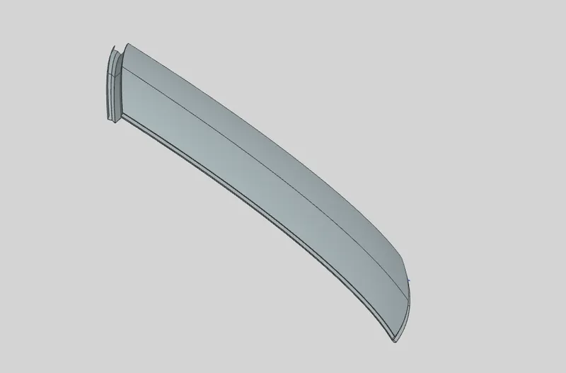
This is the outer most part of the roof which is asthetically important to the car body.
2.Front roof rail
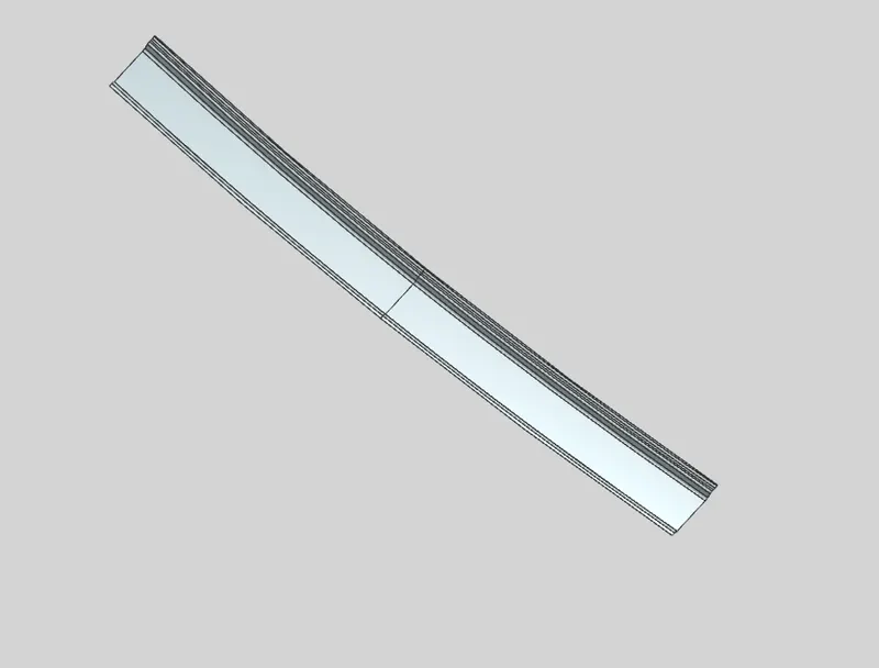
Front roof rail is the one which joins the wind shield glass , body side outer and the inner panel also. Here the front roof rail is designed based up on the master section given.
3.Bow roof
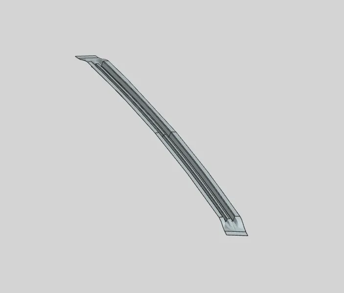
The bow roofs are give to improve the torsional stiffness and load bearing capacity of the roof structure . The number of bow roof present is depends on the overall size of the roof . Presently in this project two bow roofs are added.
4.Centre Roof Rail
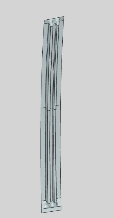
central roof rail helps in providing effectively support to the flat area of the roof as it is more susceptible to failure under the action of load . generally central roof rail is placed at the center of the roof which is connected to the B-pillar support structure . This central roof rail helps in adding the strength to the roof during the rool- over test.
Joining processes for diffrent components
Mastics are introduced between the roof outer panel and the reinforcements for joining . where ever the mastic are introduced there is remarkable improve of the strength
Spot welding is also introduced to join the reinforcements and the outer panel
Design considerations for roof design
1.Curvature study
2.Heat distortion and snow load condition criteria
3.Draft analysis
4. Section analysis
Analysis of Roof for Heat distortion
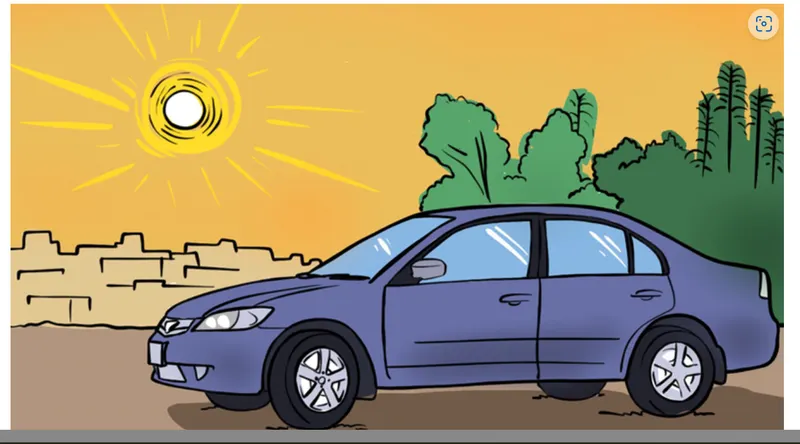
Metal softens and deforms under heat and load conditions . to evaluate the ability of sheet metal to withstand the high temperature and specific load conditions Heat distortion analysis is done .
Countries where summer heat is more there is chances of heat distortion is more due to heat distortion the specific area of roof becomes weak .
By heat distortion calculation we can find out whether the roof will withstand the conditions at that area .
if it is not withstanding the conditions we have to provide support to it .
W = [1.73 x 10^(-3) x L] + [1.85 x 10^(-8) x (R^2)/t] + [ 1.10x10^(-3) x l] - 2.68
Where
L = Roof Length in X-Direction[mm](Roof dimension in 0-Y)
R = Roof curvature
R = 2(Rx*Ry)/(Rx+Ry)
Rx = X curvature
Ry = Y curvature
t = Roof plate thickness [mm]
l = Bow Roof Span [mm]
Judgement Condition : OK< 2.7> 3.1
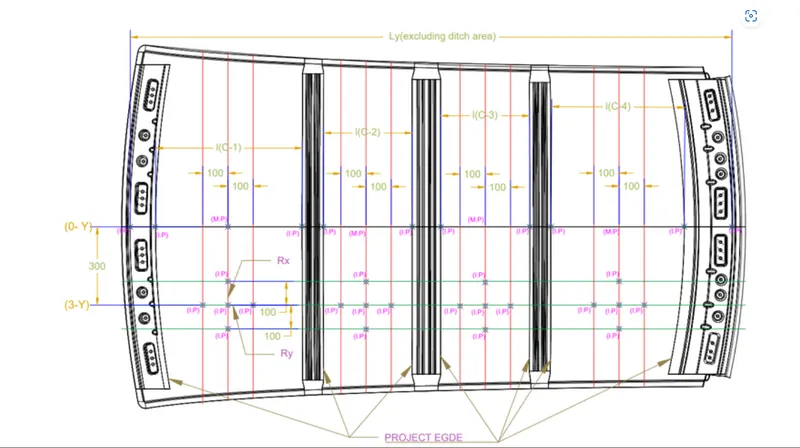
based upon the calculations the following results were observed.
| Roof rail | Rx(mm) | Ry(mm) | Rx.Ry(mm) | Rx+Ry | R(mm) | L(mm) | t(mm) | W | Result |
| Bow roof 1 | 2767.4 | 3999.69 | 11068742.11 | 6767.09 | 3271.345 | 2023.175 | 0.75 | 1.560065 | pass |
| centre roof rail | 6123.42 | 3634.76 | 22257162.08 | 9758.18 | 4561.745 | 2023.175 | 0.75 | 1.728712 | pass |
| bow roof 2 | 5997.86 | 3027.34 | 18157561.49 | 9025.2 | 4023.747 | 2023.175 | 0.75 | 1.509225 | pass |
| rear roof rail; | 4587.24 | 2629.78 | 12063432.01 | 7217.02 | 3343.051 | 2023.175 | 0.75 | 1.279101 | pass |
Conclusion
The observed values for heat distortion (W) at all section i.e bow roofs and rear roof rails is below 2.7mm thus our designed roof will sustain the heat distortion
Snow load criteria
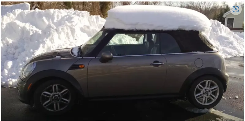
European countries suffers majar snow fall in winter season , in this seasion all the regions are covered with snow .car rooofs are also covered with snow.
Snow load criteria is followed to check/ evaluate the ability of roof to resist the permanant deformation after removal of snow over the car roof
Qr = [Iy x t2] / [α x s x [(Rx + Ry)/2]2 x 10-8]
Where
α = My x Lx2 x 10-12 , My = Y(Ly-Y)
Judgement condition = Qr ≥ 3.1
250 ≤ s ≤ 380
t = Roof plate thickness [mm]
Ly = Distance between the front and rear roof Rails on the Vehicle along with 0Y[mm]
Length of Roof panel with the center point between Roof rail Front /Rear as the reference point of the front and the rear.
Lx = Distance between the Left and Right end of the roof on the Roof BOW [mm]
Width of the roof panel exposed on the surface.
Y = Distance front Front Roof Rail to Roof BOW[mm]
s = Distance for which Roof BOW bears divided load [mm]
s = L1/2 + L2/2
Iy = Geometrical moment of inertia of Roof BOW (Y cross-section )[mm4]
Rx = Lateral direction curvature radius of roof panel Y cross-section on Roof BOW [mm]
Roof panel curvature Radius of the Length Lx in Front view
Ry = Longitudinal Direction curvature radius of the Roof panel X cross-section on Roof BOW [mm]
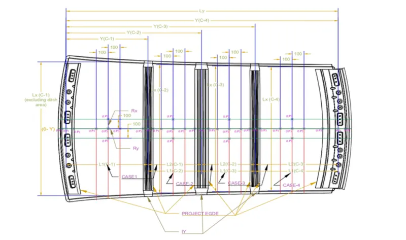
Snow load calculations parameters observations
| Roof Rails | Iy(mm) | Lx(mm) | Ly(mm) | L1 | L2 | Rx | Ry | T | Y | s | My | alpha | ((Rx+Ry)/2)^2*10^-8) | (Iy*t^2) | Qr | Result |
| Bow roof 1 | 4190 | 1144.753 | 1522.97 | 405.41 | 608.46 | 2340.25 | 4726.62 | 0.75 | 405.41 | 506.935 | 453070 | 0.59373 | 0.124851629 | 2356.875 | 62.7193 | Pass |
| centre roof rail | 8690 | 1087.354 | 1522.97 | 608.46 | 507.48 | 6061.84 | 3762.71 | 0.75 | 1013.87 | 557.97 | 516161.2 | 0.610278 | 0.241304457 | 4888.125 | 59.48925 | pass |
| bow roof 2 | 11100 | 1056.9 | 1522.97 | 507.48 | 408.46 | 4302.69 | 11494.2 | 0.75 | 1521.32 | 457.97 | 2510.178 | 0.002804 | 0.623854334 | 6243.75 | 7793.867 | pass |
Conclusion-
Roof is clearing snow load criteria Qr> 3.1
Section analysis
Section moment of inertia is used to predict the amount of deformation and deflection of a part. A higher moment of inertia is preferable as it reduces the amount of deflection for a given force. The thickness of the part and addition of flanges and embosses increase the section inertia of the part. Here the master sections of the roof and roof rails and their section analysis are given.
Section analysis of Bow roof 1
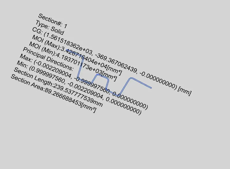
Moment of inertia max =3.42*10^4
Moment of inertia min=4.19*10^3
Section Analysis of Centre roof rail
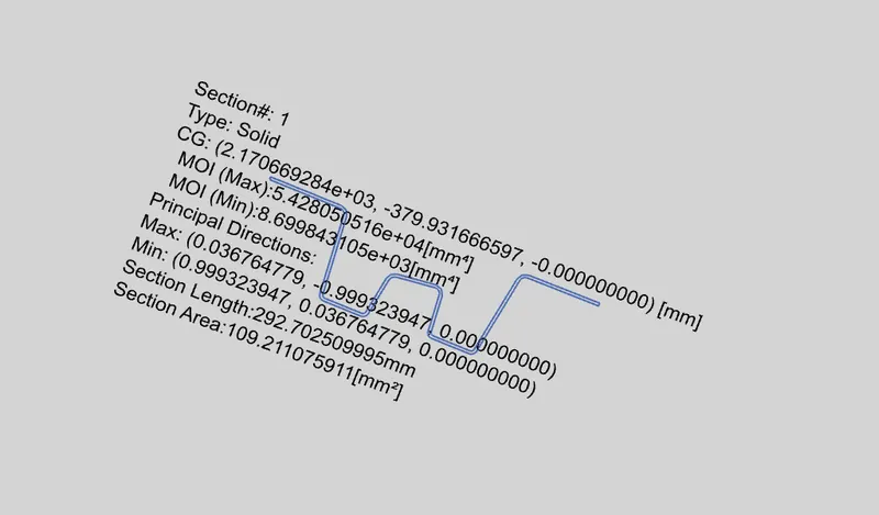
Max moment of inertia =5.42*10^4
min . moment of inertia = 8.69*10^4
Section analysis of bow roof 2
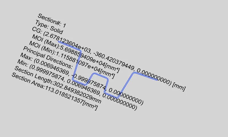
max . moment of inertia =5.69*10^4
min. moment of inertia =1.11*10^4
Section analysis of rear roof rail
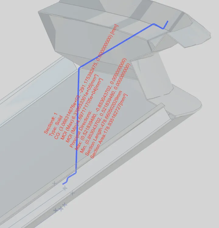
Moi max=6.33*10^5
moi min=4.69*10^4
Draft analysis
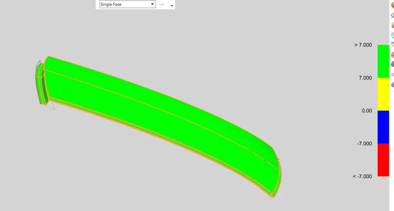
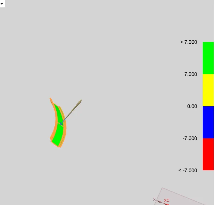
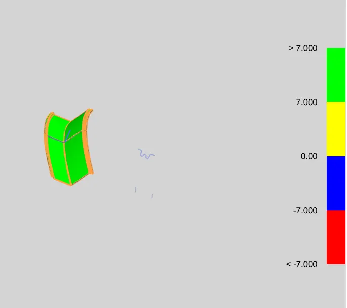
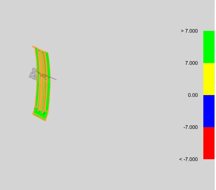
Minimum draft angle of 7 degrees is provided to all components.