Roof Design
AIM:
To Design a Roof with its components by following the master sections with all the design parameter and perform a curvature study on the roof and perform calculations to determine the position of the Bow-roofs. Also perfrom Draft analysis for all the components.
Roof:
An automobile roof or car top is the part of an automobile that positioned above the passenger compartment,It covers and protect the vehicle occupants/passenger from sun, wind, rain, and other external elements.It has given some reinforcement to give strength to this part.It is made curved because if the roof is flat then it will more prone to bend if some load applied. Roof is considered as an integral part of BIW (body in white) design. It also helps in aerodynamics of vehicle.
Roof outer panel is supported by different roof rails like front roof rail, rear roof rail, etc to provide more strength to the roof. Outer panel is also a styling surface of vehicle.
Roof Assembly Components:
- Roof Front Rail
- Bow roof Rail
- Center Roof Rail
- Rear Roof Rail
Types of Roofs:
There are diffrent types of roofs used in vehicles.
1. Hard Tops
These roofs are generally made of metal or plastics. they are rigid in nature.
2. Sunroof
A sunroof is an operable type of roof that allows for an opening in the roof of an automobile. Window like structure is present on the roof which allows air and sunight in the car.
3. Convertibles
Convertibles are passenger cars that can be driven with or without the entire roof in place. In this the roof can be fold or detach, and can be unfold of attachwhnever it is required.
Design considerations for roof:
- Material selection
- Visibility criteria
- Head room clearance
- Mastic distance
- Draft Analysis
- Depth Hight of the Reinforcements
- Weight and Strength
- Positioning of reinforcement
1) Material selection
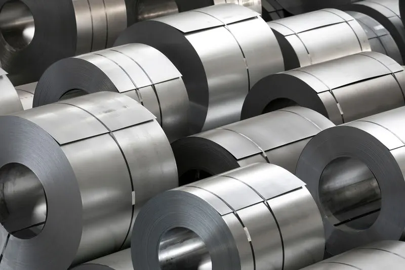
BIW is expected to possess a number of significant properties. It must have high tensile strength as well as high stiffness—bending, torsional, static, and dynamic. It must also provide good quality safety both to the car body and to its occupants against crashes of all kinds—front, rear, side, or even rollover, meeting the Federal Motor Vehicle Safety Standard No. 208 [44]. It should also be able to protect occupants from noise, vibration, and/or harshness (NVH) by absorbing or reducing these conditions. Also, it should be easy to weld and form, as well as be highly paintable and easy to design. It should provide a good surface finish that is smooth, and should also be corrosion resistant. Improvement of fuel economy also necessitates the use of lightweight materials in BIW, as it constitutes a significant share of car’s weight; in addition, given environmental concerns in recent times, it is also expected to be recyclable. Given such extensive requirements, only steel and aluminum have been used for making BIW; the former is preferred for its high strength and low cost, while the latter is preferred for its lower density that helps reduce car weight .
2) Visibility criteria
Visibility of the driver in an automotive is one of the major design consideration. Thus the Visibility criteria lines should be given to a Design engineer from the project team in order to consider it in his/her designs.
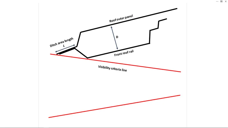
While designing the Roof outer panel and the front roof rail we need to consider the visibility criteria. The picture below gives a clear understanding about this visibility criteria
Here as the length L ‘which is the length of the front ditch area ‘ increases , its going to reduce the visibility. So it is one of the consideration here
Also as the depth of the Front roof rail D increases , again the visibility decreases. This is the second consideration
So its mandatory to maintain the visibility criteria which is given from the project management team in Both of these designs.
3) Head Room Clearance
Here the Factor which effects the head room clearance is the width of the Front Roof Rail. As the width of the Front Roof rail increases ,the Head room clearance is getting reduced.so its necessary to maintain the width of the Front Roof Rail according to the Head room clearance data given by the project team.
4) Mastic Distance
Mastics are the rubber compounds which is applied in between two sheet metal BIW components where spot welding is not applicable.
Mastic distance here is the distance between the roof outer panel and the surface of the reinforcement where the mastic are applied. This distance must be maintained in between 2 mm to 8 mm
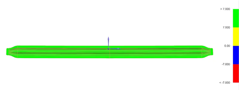
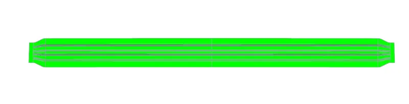
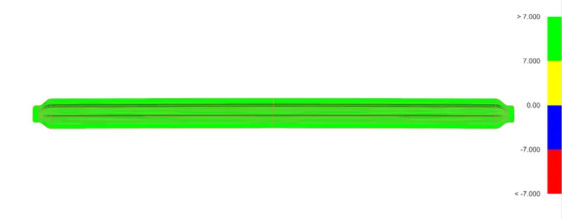
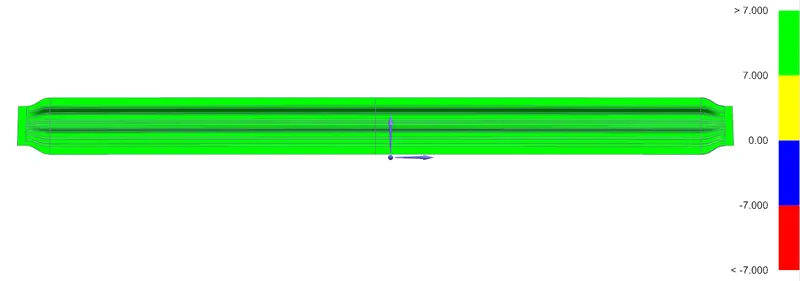
5)Draft Analysis
Draft analysis helps to know about the manufacturability of component. Design engineer need to consider the draft angle while creating the component and also ensure the design using Draft analysis of component.
6) Depth Hight of the Reinforcements
Depth or the height of the reinforcements (Bow roofs) are another design consideration. In a car the Bow roofs lies in between the Head liner and the Roof outer panel. So as the depth of the bow roof increase the interior space is get reduced. In common cases the depth of the bow roofs doesn’t exceed 15 mm , But in some cases it changes according to cars.
7) Weight and Strength
This factor is compulsory considered in each and every components of BIW. Because todays car manufactures mostly focusing on reducing the over all weight of the car with out compromising the strength of the parts . So its better to remove some extra materials from the designs with out losing its strength. One of the method used to strengthen the parts are the Embosses
8) Positioning of Reinforcements
Positioning of the bow roofs have the major role in the strength of the Roof. The roof must be capable to withstand high temperature and load with respect to the positioning of Reinforcements which contributes more strength.
So we have two criteria to check whether the position of the Bow roof are correct or not. They are
Heat distortion Criteria
The heat distortion value ‘W’ must be less than 2.7 to ensure that , the roof can withstand high temperature .
Snow Load Criteria
In the winder season , in some countries there will be a huge load of snow on the roof top of the car. So for the roof it is necessary to have enough strength to bear this snow load. Thus the snow load value ‘Qr’ for the roof must be grater than 3.1
To check design, CAE team performs various analysis and simulation to validate the desig and after the validation final design is manufactured.
Roof Crush Test-
ROOF CRUSH TEST:
OVERVIEW OF THE TEST:
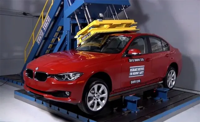
Roof strength evaluations consist of a quasi-static test conducted on a vehicle’s roof in a manner similar to tests used to determine compliance with Federal Motor Vehicle Safety Standards 216 (Office of the Federal Register, 2009). The main difference between the procedure specified by the Insurance Institute for Highway Safety (IIHS) and that specified by the U.S. federal government is that the IIHS procedure is,
- Specifies testing one side of a vehicle’s roof
- Does not include a headroom criterion
- Specify testing for a given displacement instead of a given force level
- Specify setting the vehicle’s pitch angle during testing based on the measured on-road pitch angle.
- An overall rating is assigned based on the peak strength-to-weight ratio (SWR) measured within 127 mm of plate displacement.
CURB WEIGHT MEASUREMENT:
Curb weight values used for calculating the SWR are based on IIHS measurements of a vehicle, not the manufacturer’s specified curb weight.
Vehicle curb weight is measured with full fluid levels using scales manufactured by Longacre Racing Products (Computer scales DX series 72634).
TEST VEHICLE SELECTION:
For information on how we select vehicles for our crash test programs, including how we define typically equipped vehicles, see Test Vehicle Selection (IIHS, 2021). Whenever possible, the vehicle acquired for testing is the same vehicle used for the curb weight measurement.
At times, it is necessary to test a vehicle that does not meet the IIHS definition of a typically equipped vehicle, and the curb weight measurement is applied from another vehicle that does meet the definition. In these cases, the test vehicle does not differ from our typically equipped vehicle definition in any way that might influence the roof strength (e.g., a vehicle with a sunroof would not be tested if the typically equipped vehicle lacks this option).
Once the test vehicle has been acquired, either the driver or passenger side of the vehicle will be selected for testing. For most vehicles, the test side is chosen at random. However, for roof designs that appear asymmetrical, engineering judgment is used to select the sides of the roof that may result in a lower peak force.
TEST VEHICLE PREPARATION:
With the vehicle on a level surface, the on-road pitch angle at the front door sill is measured on both sides of the vehicle. Unless the vehicle manufacturer requests otherwise, roof racks and other non-structural items that may be contacted during the test are left as installed from the factory.
Any trim or other components are removed if they interfere with supporting the vehicle along its locker panels. For vehicles with vertical pinch weld flanges on the bottom of the locker panels, the vehicle support system consists of one I-beam (HR A-36 W4X13) for each locker panel.
Each I-beam has a clamping system incorporated on the top that is tightened against the pinch weld flange to clamp the system in place. When the pinch weld flange has a bend that prevents supporting the sill with one I-beam, more than one I-beam can be used on each side of the vehicle.
For vehicles with no pinch weld flange, or with a no vertical flange angle that precludes clamping, mounting by another method may be necessary, such as that described in the National Highway Traffic Safety Administration’s Laboratory Test Procedure (2006).
Prior to testing, the front-row seat back on the side being tested was reclined to prevent interaction with the crushing roof. The rear seats are latched into their upright position. All windows are closed and doors are locked.
TESTING ROOF:
Roof strength evaluations are conducted on a quasi-static test system manufactured by MGA Research Corporation
The system consists of an upright assembly and an attached loading head that can be fixed at varying heights from the ground as well as at pitch angles ranging from −5 to +5 degrees to accommodate testing on the driver or passenger side.
The roll angle is permanently fixed at 25 degrees. Four hydraulic actuators control the movement of the plant along two linear guides. The entire system is mounted on a T-slot bed plate anchored to the floor of the test facility.
Roof Curvature Study
Heat Distortion Criteria:
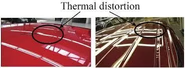
- What Is Heat Distortion/ Thermal Distortion:
Heat distortion temperature is the temperature at which the metal softens and deforms under a specific load.
Roof of a car is probably the only component which is exposed to sun for almost all the time, so this study is done to check the ability of the roof to withstand high temperature with respect to the positioning of the reinforcements which contribute to increased strength.
- Calculation:
W = [1.73 x 10^(-3) x L] + [1.85 x 10^(-8) x (R^2)/t] + [ 1.10x10^(-3) x l] - 2.68
Where,
L = Roof Length in X-Direction[mm](Roof dimension in 0-Y)
R = Roof curvature
R = 2(Rx*Ry)/(Rx+Ry)
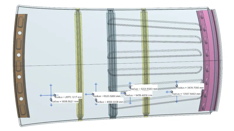
Rx = X curvature
Ry = Y curvature
t = Roof plate thickness [mm]
l = Bow Roof Span [mm]
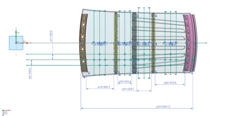
Rx and Ry Calculation:
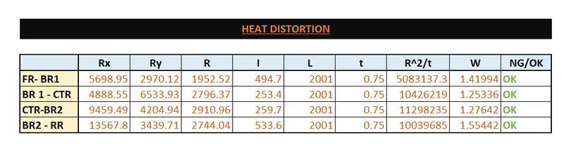
Result:
From above table,
The value of W is less than 2.7 in all the cases. Therefore the design is OK and we can proceed for further.
Snow Load Condition
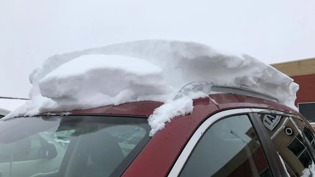
This study is useful to check the roofs stiffnes in snowfall regions. In some countries heavy snowfall occurs. So using this we can check whether the roof can sustain for the snow load or will there be any deformation after removing the snow.
Calculation:
Qr = [Iy x t2] / [α x s x [(Rx + Ry)/2]2 x 10-8]
Where,
α = My x Lx2 x 10-12 , My = Y(Ly-Y)
t = Roof plate thickness [mm]
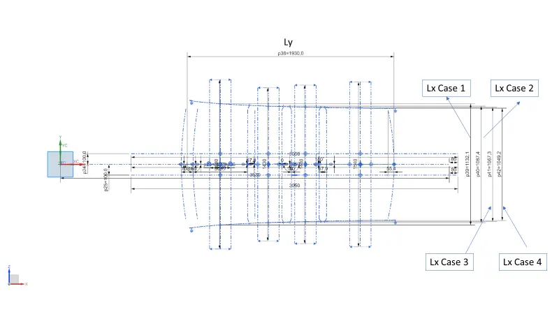
Ly = Distance between the front and rear roof Rails on the Vehicle along with 0Y[mm]
Length of Roof panel with the center point between Roof rail Front /Rear as the front and rear reference point.
Lx = Distance between the Left and Right end of the roof on the Roof BOW [mm]
The width of the roof panel is exposed on the surface.
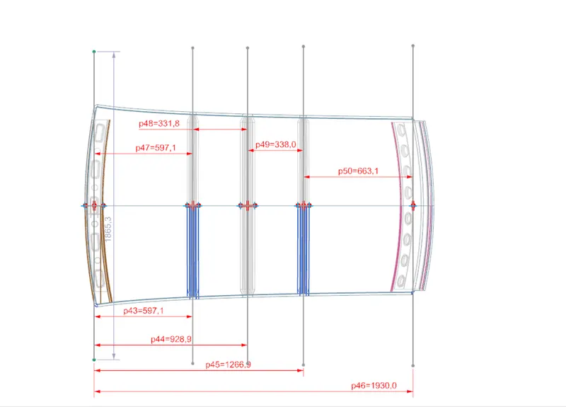
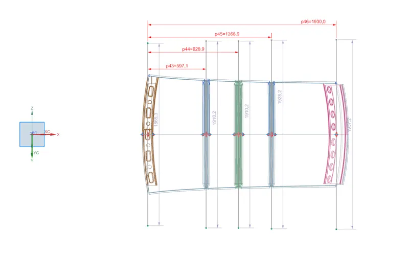
Y = Distance front Front Roof Rail to Roof BOW[mm]
s = Distance for which Roof BOW bears divided load [mm]
s = L1/2 + L2/2
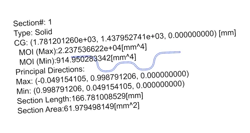
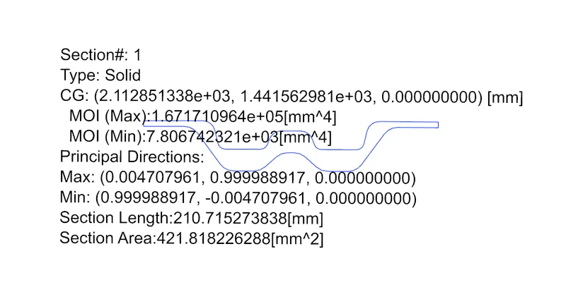
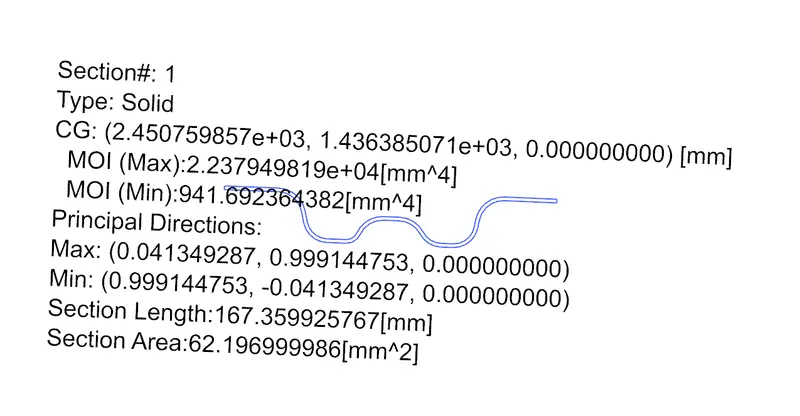
Iy = Geometrical moment of inertia of Roof BOW (Y cross-section )[mm4]
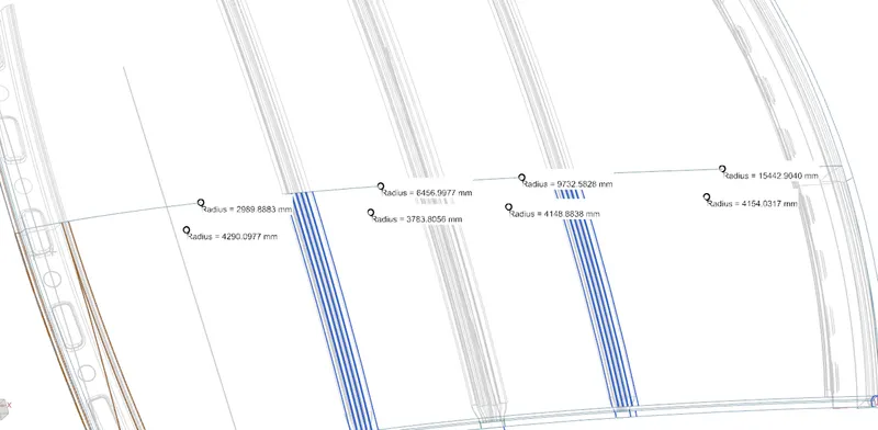
Rx = Lateral direction curvature radius of roof panel Y cross-section on Roof BOW [mm]
Roof panel curvature Radius of the Length Lx in Front view
Ry = Longitudinal Direction curvature radius of the Roof panel X cross-section on Roof BOW [mm]
Roof panel X curvature radius of length s in Side view
Calculations:
Lx And Ly Calculation
Rx and Ry Calculation:
Y and L1 and L2 calculation:
Y calculation:
Moment Of Inertia Calculation using Section Analysis Option:
Moment Of Inertia of Bow Roof 1-
Moment Of Inertia of Center Bow Roof-
Moment Of Inertia of Bow Roof 1-
Calcuation of Qr-
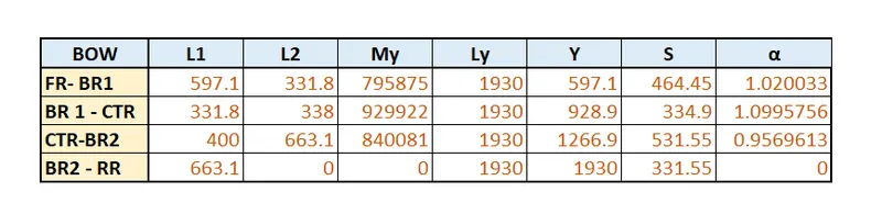
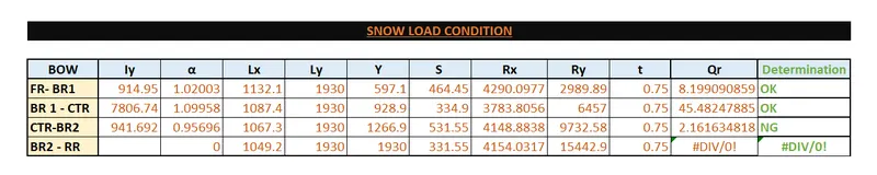
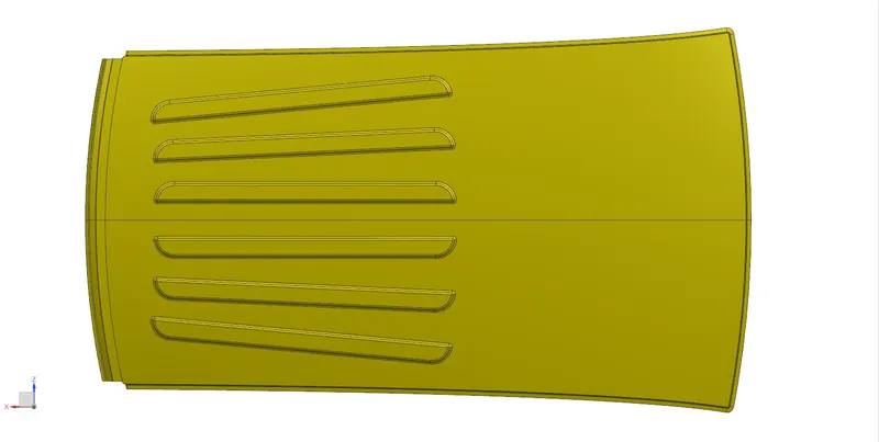
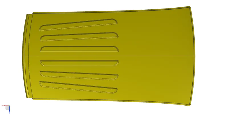
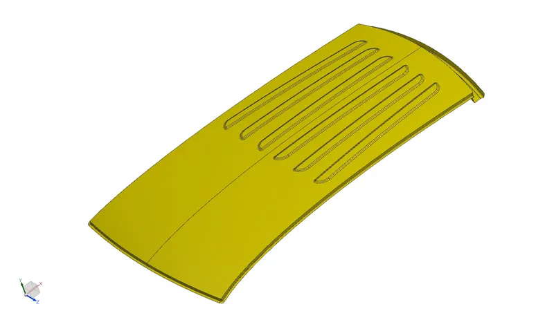
From the calculation we found that the Qr value is greater than 3.1. So it is satisfying the condition. But for 3rd case it is not satisfying, so to gain more strength the roof outer panel need to emboss
Final Design Screenshots:-
Roof-
Front Roof Rail-
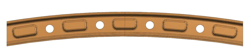
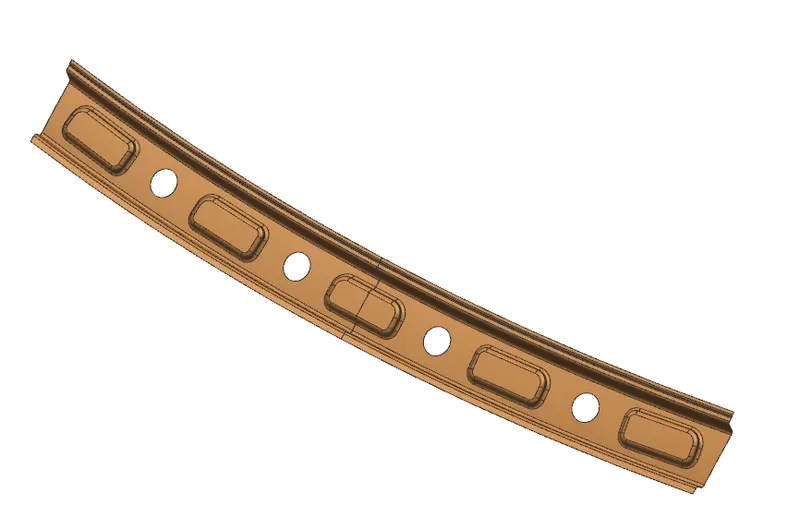
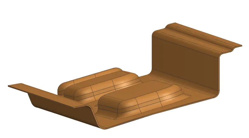
Bow Roof 1-
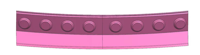
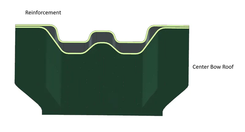
Center Roof with reinforcement-


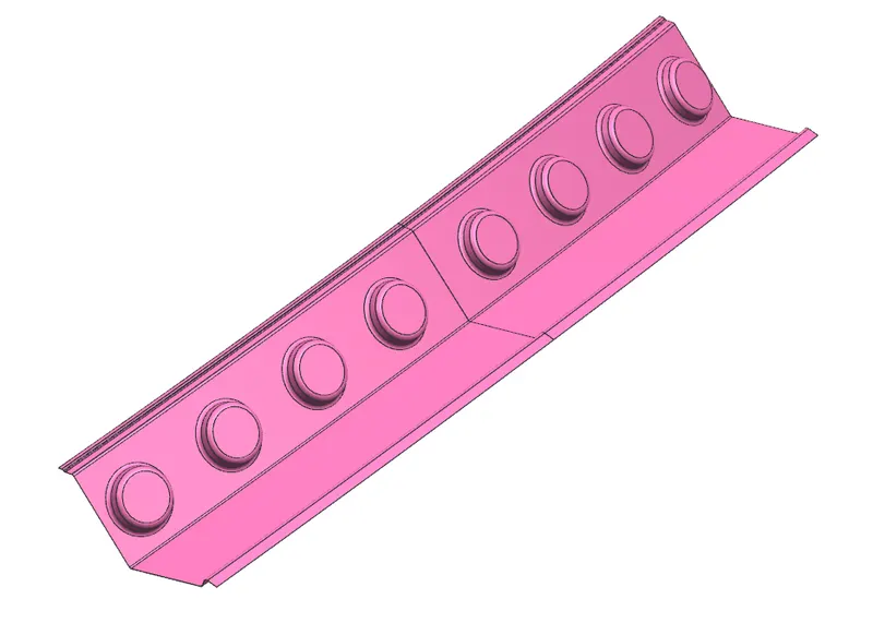
Bow Roof 2-

Rear Roof Rail-
Roof Assembly-
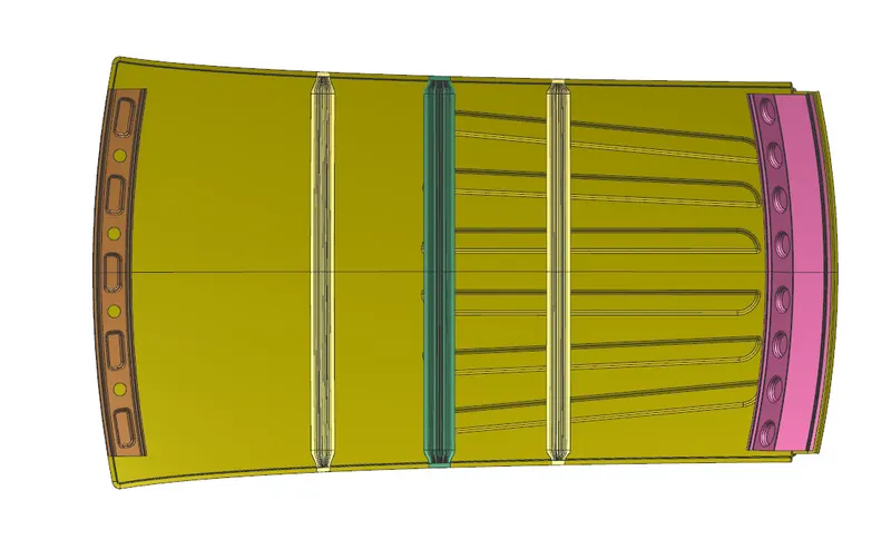
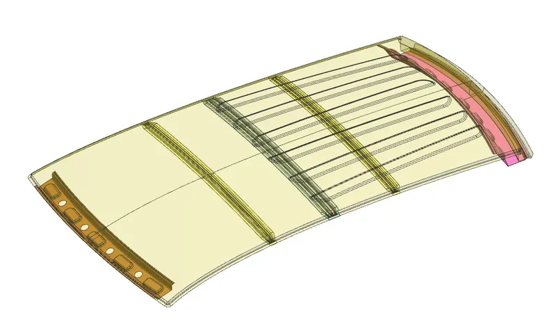
Draft Analysis
CONCLUSION:
Succcessfully
- Created the roof assembly from given master sections.
- Performed the draft analysis.
- Done the curvature study and confirmed the locations of bow roofs.