Roof Design
IN THIS PROJECT WE WILL LEARN HOW TO DESIGN ROOF DITCH AREA,FRONT ROOF RAIL, BOW ROOFS,AND REAR ROOF RAIL.
CREATING THE ROOF DITCH AREA:
First we will recieve the input of class A of the roof from that we have to make the rest of the things. the roof outer panel is as follows:
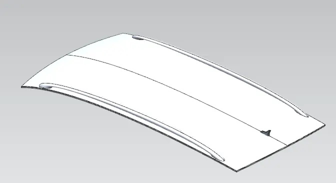
But before creating the ditch area we have to extract the geometry and untrim the unwanted surfaces and we want only half of the surface because the other half is symmetric.
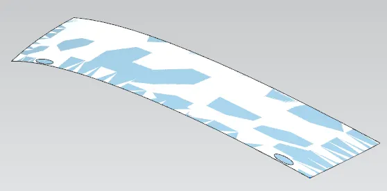
after doing the untrim we have to trim all the sharp corners. So now we will create the outer panel as per the master section but before creating the outer panel we have to do our design in such a way that we can modify our design at any time without disturbing other components.
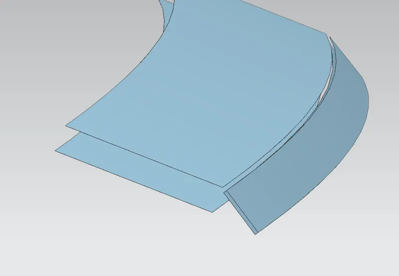
so for that we will use law extension and for us the given opening angle for the ditch area is 7 degrees so we will use law extion on the curves of the outerpanel and then we will recieve the output as follows:
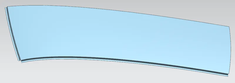
after getting this we have a open at the corner to close that corner we have to use the through curve mesh and we will recieve the output as follows:
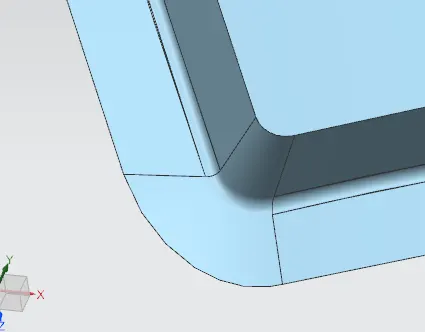
so once if we done upto here we have got the pitch area.
CREATING THE REAR END OF THE ROOF OUTER PANEL:
so as per the master section we have to create the rear end of the roof outer panel so for that also we will use the law extension of the and we will get the output as follows:
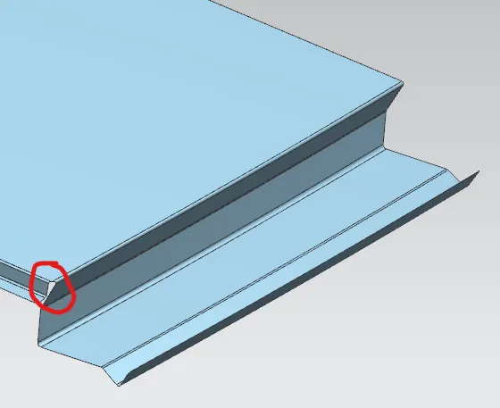
after creating the rear end of the roof outer panel we will give a relief over the end of the ditch area and the rear end of the outer panel. and we will apply the required blends and we will get a complete roof outer panel.
REASON FOR CREATING THE ROOF DITCH AREA.
the roof ditch area is the area which connects the front glass and with hood and the A pillar is also connencted to the roof.
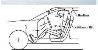
the roof has to be designed in such a way that we have to consider head room clearence also.
what is HEAD ROOM CLEARENCE:
The measurement of headroom is the distance from a vehicle's roof to its seat bottom. Sometimes, you'll see maximum and minimum values for this car spec published since most automobiles have seats that adjust up and down.
CREATING THE FRONT ROOF RAIL:
for creating the front roof rail we have the master section so the cfreating steps are as follows:
1.first we will create a exact surface like the outer panel by using the wave link geometry.
2.and then we will offset the surface as per the required distance.
3.we will use a datum plane to the curve of the offsetted surface for required distance to trim the extra portions.
4.and then we will use the offset curve in face and we will give the distance as per the datum plane and we will trim the extra portions.
5.after that we will create the falnges using law extension as per mastersection.
6.after creating all the flanges we will usew them all together and provide the necessari blends.
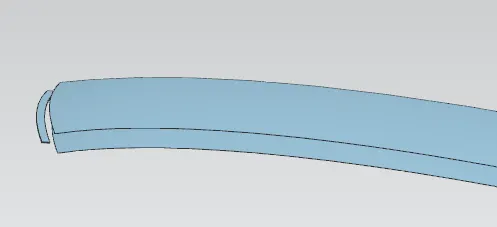
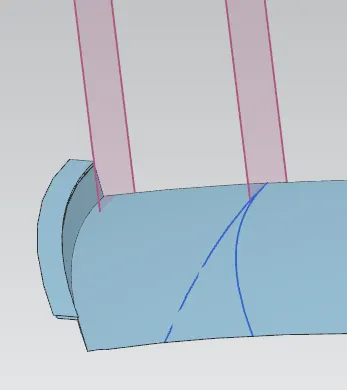
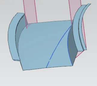
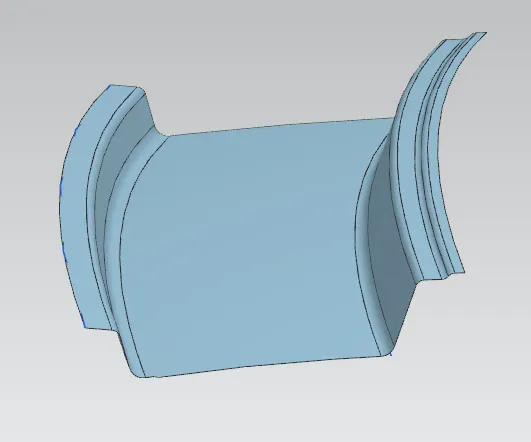
after creating all the above things we have to leave the space for the A pillar mounting but the A pillar mounting size is not given so we will leave the space approximately by trimming the front roof rail a littlt abit by using a datum plane.
CRAETING THE CENTRE ROOF RAIL:
for creating the centre roof rail we have to place the roof in the centre of the roof but in our roof the curvature is more in front than the rear end so we will create the out centre in somewhere centre but not exactly centre so it will be place somewhere on the 55 to 60% of the roof.
for the centre roof rail also we have the master section and we will create the mcentre roof rail as per it.
the offseting and trimming the surface steps all are same as the front roof rail here we have maintain the distance. and the rest of the steps are same as the front roof rail.
to find the 55% of the roof we will use the datum plane on the curve and then we will give arc length as 55% and then we will take the intersection curve and then we will offset the surface to the required distance and then we will project the intersection curve on the offsetted surface and then we willl offset the projected curve on the surface to the required distance and then we will trim the sheet.
after trimming the sheet we will use law extension to get the flanges then we will offset the surface and use trimand extend and after all that we will sew all them together and then we will give the necessary blends..
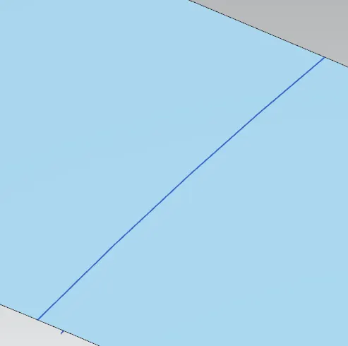
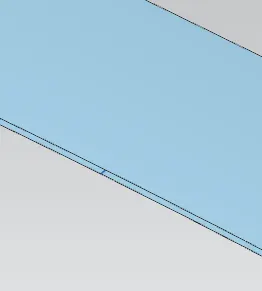
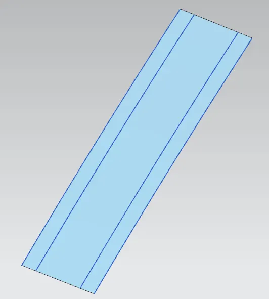
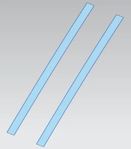
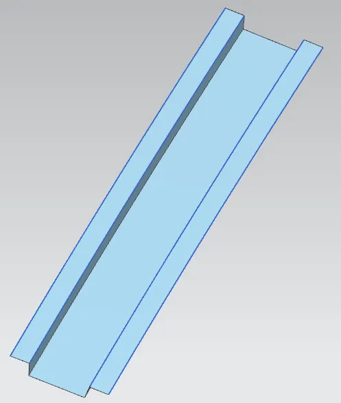
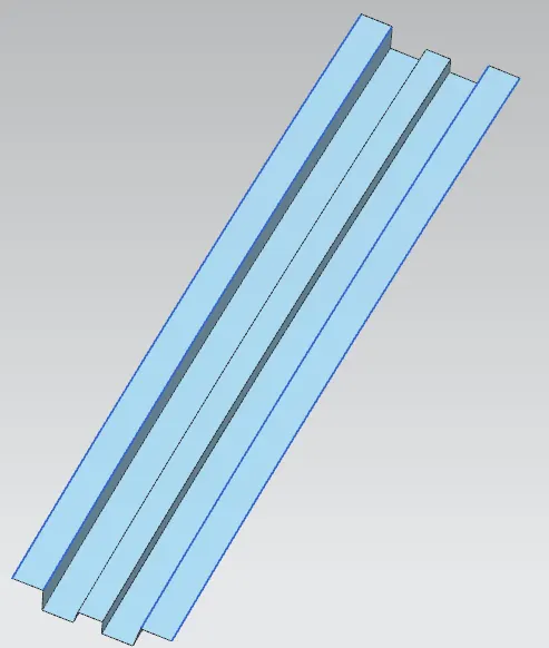
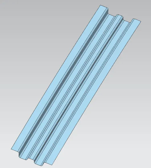
after creating all these we have to cut a little portion of roof ditch area and a little area of centre roof rail and then we have to create the bridge curve on the edges of the both surface and then we have use the swept command and then we have to join then all by sew and we will recieve the output as follows:
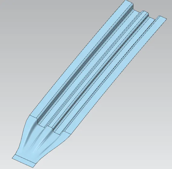
CREATING REAR ROOF RAIL:
the rear roof rail is the part which will be connected with the back door as well as the C pillar and it will be help full for the rear side of the roof to make the roof stronger and it will be having the emboss to mount the other things also
for creating the rear roof rail we have the master section so the steps are as follows:
1.first we will extract all the needed faces of roof for the rear roof rail
2.then we will create the the extra surfaces as per the master section by using law extension and the angle and the measurments are given in the master section
3.we will create all the flanges which is looking vertical by law extension.
4.after creating all the falnges we will give the required blends.
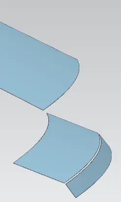
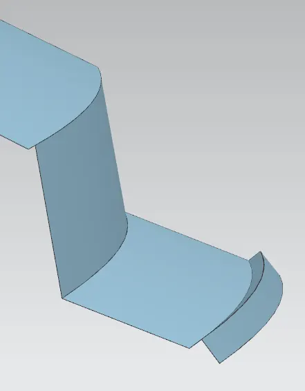
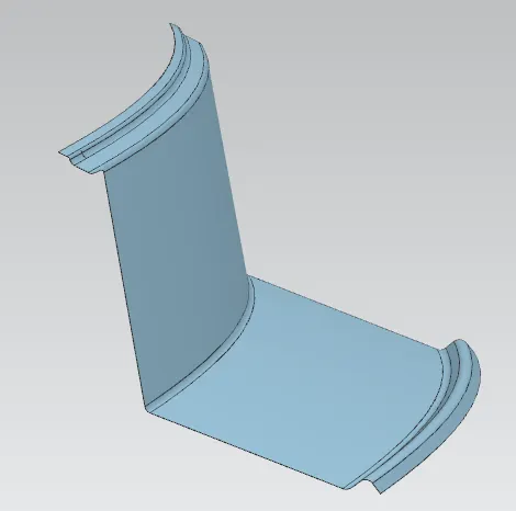
here also we need to give the gap for C OR D pillar hence we are not having the data of C pillar so we will give a approximate gap by creating the plane on the curve and trimming the sheet with the plane.
CREATING THE BOW ROOFS:
use of bow roof:A Roof Bow is a sheet metal part, usually spot welded to the BIW inner frame, forming the inner structure of the vehicle body. Its primary function is to supporting the roof panel loads, such as Oil Canning and local stiffness.
for our model the we are going to locate the bow in the middle of front roof rail and centre roof rail and then from centre roof rail to rear roof rail.for locating the middle point we have simply take a point on the rear edge of the front roof rail and front edge of the centre roof rail and then we have to take a midpoint and that will be our mid point for bow roof 1.
the steps all are same as the centre roof rail only the measurments varies.
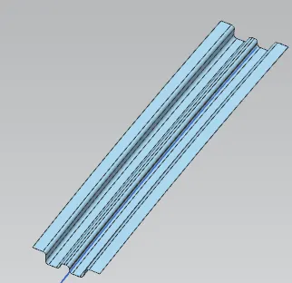
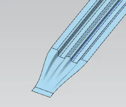
like the same procedure we have to do for the bow roof 2 also. after all these we have to extend the sheet a little bit and then we have to trim the sheet acoording to the mid plane and then we have to mirror it according to the midplane and then we have to sew them together to make it as a single plane.
after doing all these we have to check the draft analysis for our components.
CHECKING DRAFT ANALYSIS FOR DIFFERENT COMPONENTS IN OUR ROOF ASSEMBLY:
ROOF:steps for doing draft analysis
1.first we have to select the object and then we have to select the vertical vector(tooling direction).
the minimum draft angle for our component is 7 degree
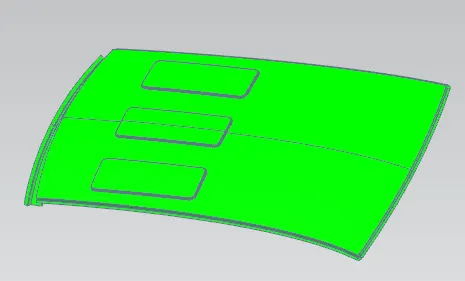
FRONT ROOF RAIL:
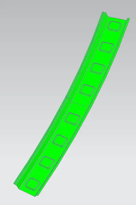
REAR ROOF RAIL:
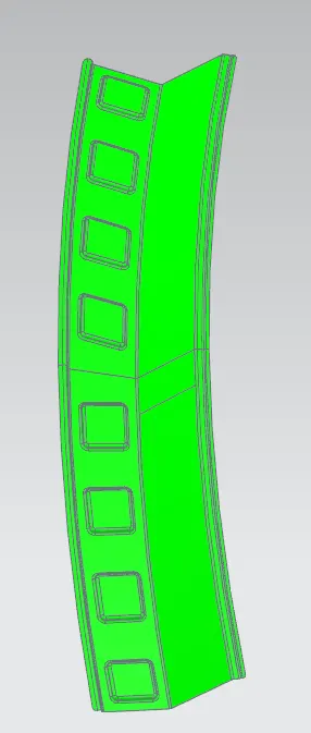
CENTRE ROOF RAIL:
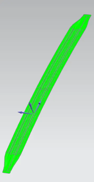
BOW ROOF 1 AND 2:
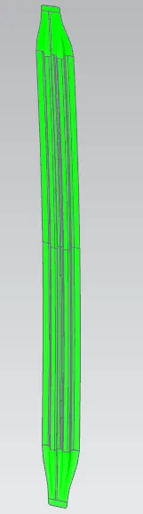
HEAT DISTORTION:
Heat distortion condition: Heat distortion temperature is the temperature at which the metal softens and deforms under a specific load.
for calculating the heat distortion we have a formula the formula is as follows:
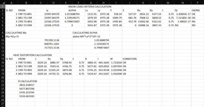
Qr = [Iy x t2] / [α x s x [(Rx + Ry)/2]2 x 10-8]
where,
α = My x Lx2 x 10-12 , My = Y(Ly-Y)
t = Roof plate thickness [mm]
Ly = Distance between the front and rear roof Rails on the Vehicle along with 0Y[mm]
Length of Roof panel with the center point between Roof rail Front /Rear as the front and rear reference point.
Lx = Distance between the Left and Right end of the roof on the Roof BOW [mm]
The width of the roof panel is exposed on the surface.
Y = Distance front Front Roof Rail to Roof BOW[mm]
s = Distance for which Roof BOW bears divided load [mm]
s = L1/2 + L2/2
Iy = Geometrical moment of inertia of Roof BOW (Y cross-section )[mm4]
Rx = Lateral direction curvature radius of roof panel Y cross-section on Roof BOW [mm]
Roof panel curvature Radius of the Length Lx in Front view
Ry = Longitudinal Direction curvature radius of the Roof panel X cross-section on Roof BOW [mm]
Roof panel X curvature radius of length s in Side view
and the judgement condition is Qr≥ 3.1
so let us calculate
so first we will calculate the ly which is from the front edge of the styling surface and the rear edge of the styling surface in 0Y direction.
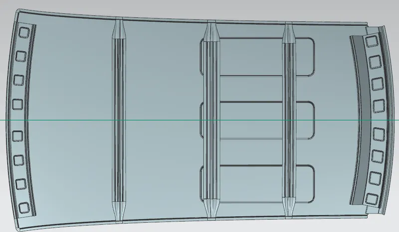
from that 0Y line we will offset that line downward 300 mm and then we will offset the 300mm line for 100 mm upwards and downwards
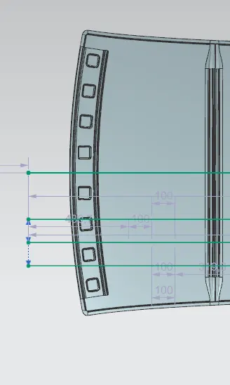
and after that we will take a point on the rear end of the front roof rail and the point on the front end of the bow roof 1 and then we will take a mid point from that two point and then we will make vertical line from that vertical line we will offset that line 100mm right and left
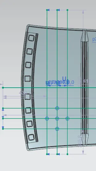
after getting these lines we will take intersection points on the threee lines and we will project that intersection points on the roof and we will recieve the output as follows:
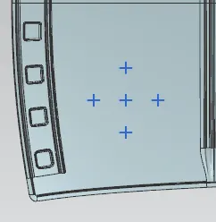
after projecting the points we will create a three point arc on the points vertically and horizontally
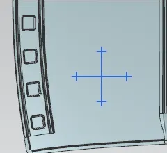
and the vertical arc will be our Ry and the horizontal arc will Rx
CALCULATIONS OF SNOW LOAD AND HEAT DISTORTION: