Roof Design
AIM : To
i)Create an assembly for the given Roof styling by developing the essential flanges for the outer roof and creating the reinforcements
ii)Provide appropriate dimensions and to check for Draft analysis.
iii)Do a curvature study on the roof and perform calculations to determine the position of the Bow-roofs.
iv) Suggest and implement remedies in the design if the creation is not full-filling
Start with the creation of a roof ditch area with a tool opening angle of 7 degrees.
Develop the reinforcements as separate parts
CAR ROOF :
An automobile roof or car top is the portion of an automobile that sits above the passenger compartment, protecting the vehicle occupants from sun, wind, rain, and other external elements.
Roof is the structure above the wind shield glass having the reinforcements to provide the strength to the overall structure and to with stand the over head forces like snow
When it is seeing from outside of the car, it is just closing the top portion. But in design point of view, it is hard to create the design. Because of you have to create no of support rails for enough strength to withstand the load. Bow roofs are primarily fixed in flatter region to enhance strength.
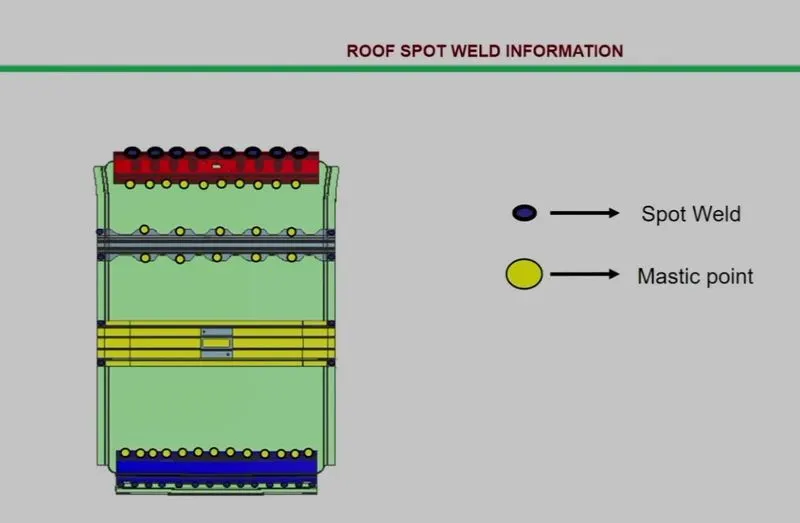
Front roof and rear roof rails are fixed to the ditch area using spot weld operation. But front, rear bow roof and center roof rails are fixed to roof using mastic sealants. We don’t want so much gap between roof rails and bow roof area. So, we reducing the NVH issues.
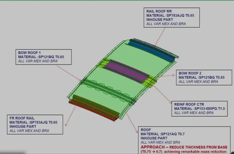
Reinforcements:
Different types of reinforcements that the car has are :
- Front roof rail
- Bow roofs
- Central roof rail and
- Rear roof rail
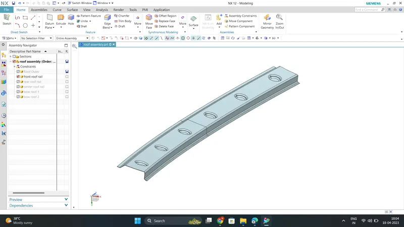
1)Front roof rail
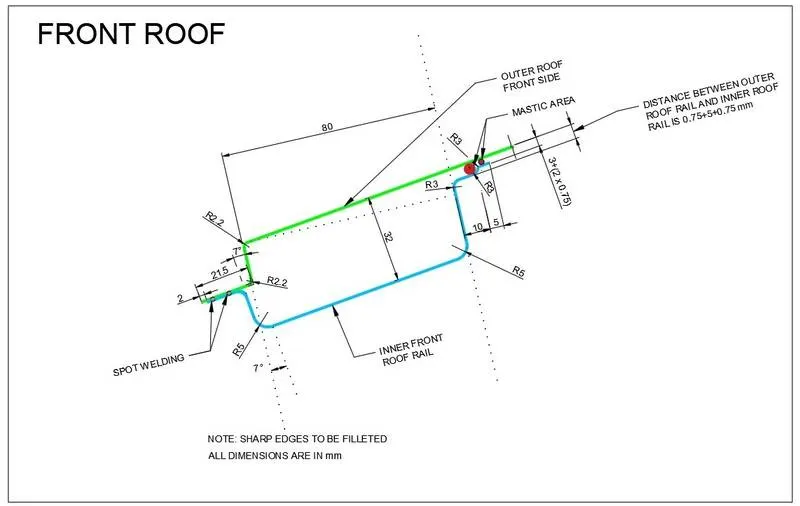
Front roof rail is the one which joins the wind shield glass , body side outer and the inner panel also. Here the front roof rail is designed based up on the master section given
2)Bow Roofs
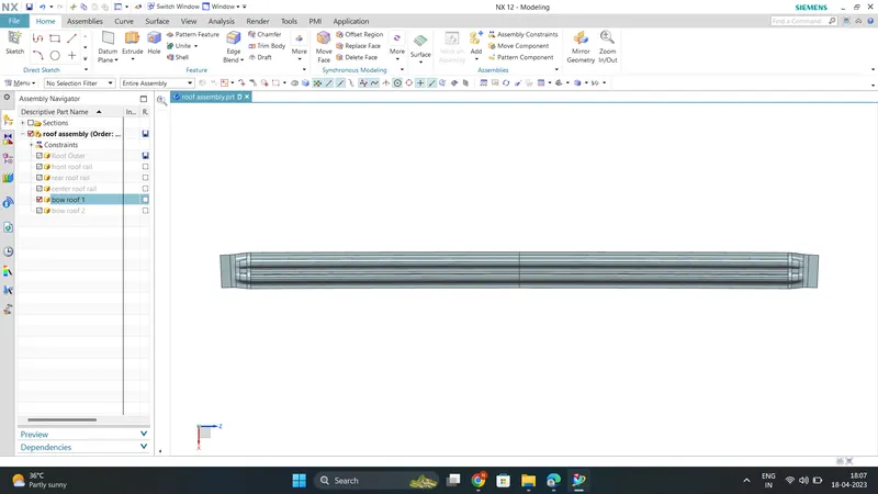
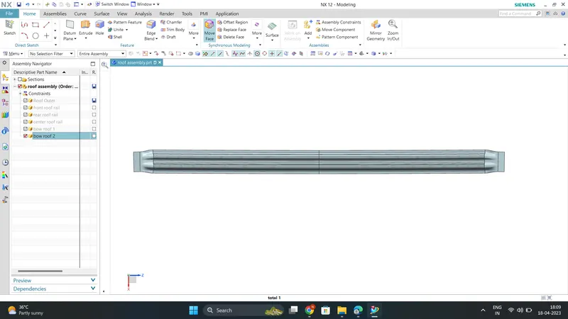
The bow roofs are give to improve the torsional stiffness and load bearing capacity of the roof structure . The number of bow roof present is depends on the overall size of the roof .
Presently in this project two bow roofs are added.
Bow Roof-1
Bow Roof-2
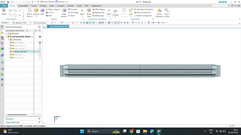
Centre Roof Rail
Centre roof rail helps in providing effectively support to the flat area of the roof as it is more susceptible to failure under the action of load .
Generally central roof rail is placed at the center of the roof which is connected to the B-pillar support structure .
This central roof rail helps in adding the strength to the roof during the rool- over test. The thickness of the central roof rail is 1.25 mm .
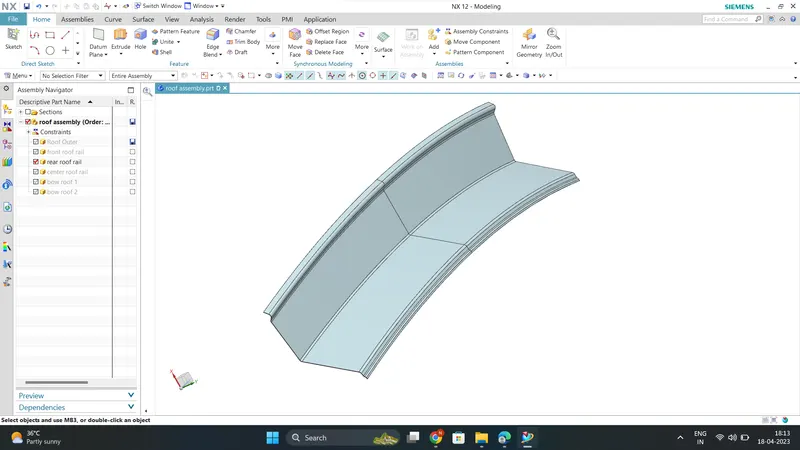
Rear Roof Rail
Rear roof rail is the one which joins the back door and the body side outer
DESIGN CONSIDERATIONS FOR A ROOF :
- Visibility criteria
- Head clearance
- Bow roof positions
- Heat distortion and snow load criteria
- Draft analysis
ROOF CRUSH TEST :
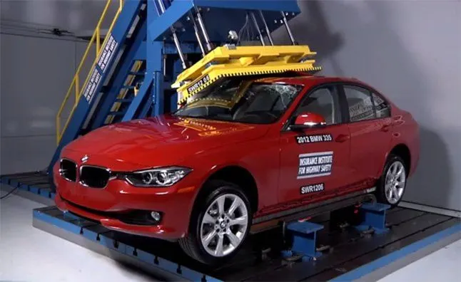
Roof crush test is the design given by the IIHS ( insurance institute of highway safety ) . After analyzing the many accidents IIHS has then fixed some regulations , that how to perform the crush test .
IIHS gives the rating based up on this test . For this they consider two points while giving the rating
- How fast the car can reforms to its original shape after the roll over and
- How deep is the protrusion after the roll over
GOAL OF ROOF CRUSH TEST :
To minimize the protrusion into the occupant compartment , so that the seat belts and air bags can do there job in protecting the occupant
CONDITIONS TO FOLLOW FOR ROOF CRUSH TEST :
There are two conditions that should be followed for the roof crush test , they are
INITIAL CONDITION :
- Close and lock all the doors
- Close all the windows
SECOND CONDITION :
Fix the body sill or chassis frame on a hard lever surface horizontally
METHOD OF APPLYING THE FORCE :
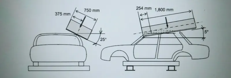
The load is applied in such a way that 50 is tilted from the front end to the rear end and the load will be in 1800 mm in length and 750 mm in width . The load is applied at the position of 250 from the flatness of the roof . The load is applied on the roof for almost 120 sec and the crush speed at which the load applied is 13 mm/sec or less than that
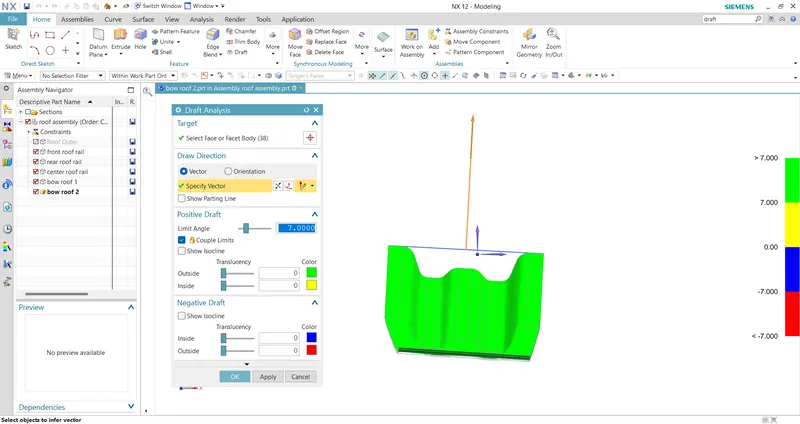
- Perform Draft Analysis for all the parts and include the snapshot in the report
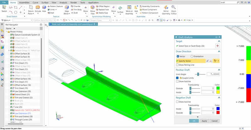
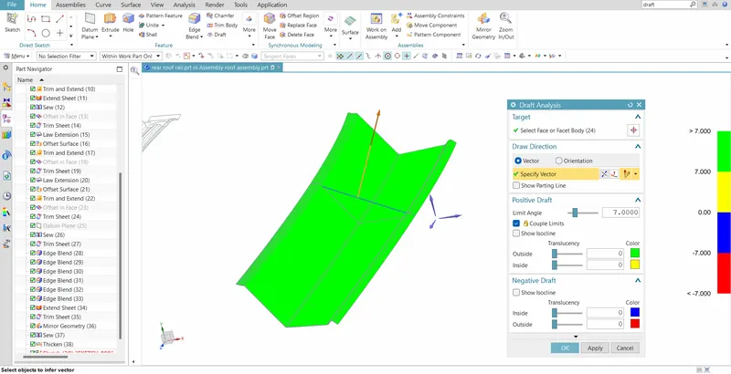
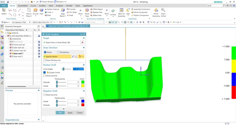
The Draft Analysis command enables you to detect if the part you drafted will be easily removed or not . This type of analysis is performed based on color ranges identifying zones on the analyzed element where the deviation from the draft direction at any point, corresponds to specified values.
Minimum draft angle of 70 is considered for analysis . Green colour infer on the parts that all face along the tooling direction has positive draft angle .
1)Front Roof rail
2)Rear Roof rail
3)Bow Roof-1
4)Centre Roof Rail
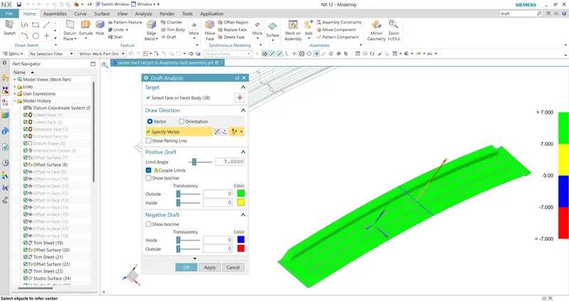
5)Bow Roof-2
- Manufacturing techniques : The various Manufacturing Techniques are
1) Stamping :
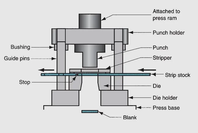
The working Components are the punch and die, which perform the cutting operation. They are attached to the upper and lower portions of the die set, respectively called the punch holder(or upper shoe) and
die holder (lower shoe). The die set also includes guide pins and bushings to ensure proper alignment between the punch and die during the stamping operation. The die holder is attached to the base of the press, and the punch holder is attached to the ram. Actuation of the ram accomplishes the pressworking operation.
In addition to these components, a die used for blanking or hole-punching must include a means of preventing the sheet metal from sticking to the punch when it is retracted upward
after the operation. The newly created hole in the stock is the same size as the punch, and it tends to cling to the punch on its withdrawal. The device in the die that strips the sheet metal
from the punch is called a stripper. It is often a simple plate attached to the die with a hole slightly larger than the punch diameter.
For dies that process strips or coils of sheetmetal, a deviceis required to stop the sheet metal as it advances through the die between press cycles. That device is called a stop.
Stops range from simple solid pins located in the path of the strip to block its forward motion, to more complex mechanisms synchronized to rise and retract with the actuation of
the press.
2)Embossing :
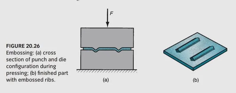
Embossing is a forming operation used to create indentations in the sheet, such as raised (or indented) lettering or strengthening ribs . Some stretching and thinning of the metal are involved. This operation may seem similar to coining. However, embossing dies possess matching cavity contours, the punch containing the positive contour and the die containing the negative; whereas coining dies may have quite different cavities in the two die halves, thus causing more significant metal deformation than embossing.
3) Bending:
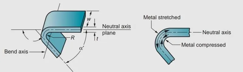
Bending in sheet-metal work is defined as the straining of the metal around a straight axis . During the bending operation, the metal on the inside of the neutral plane is
compressed, while the metal on the outside of the neutral plane is stretched. The metal is plastically deformed so that the bend
takes a permanent set upon removal of the stresses that caused it. Bending produces little or no change in the thickness of the sheet metal.
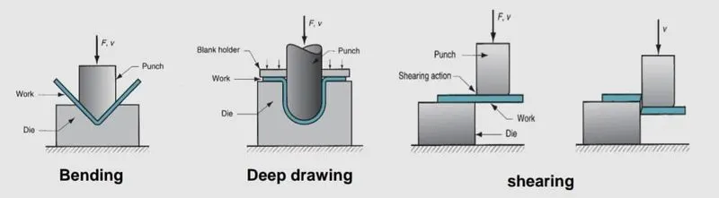
Bending operations are performed using punch and die tooling. The two common bending methods and associated tooling are V-bending, performed with a V-die; and
edge bending, performed with a wiping die.
In V-bending, the sheet metal is bent between a V-shaped punch and die. Included angles ranging from very obtuse to very acute can be made with V-dies.
V-bending is generally used for low-production operations. It is often performed on a press brake and the associated V-dies are relatively simple and inexpensive.
Edge bending involves cantilever loading of the sheet metal. A pressure pad is used to apply a force to hold the base of the part against the die, while the punch forces the
part to yield and bend over the edge of the die. In the setup edge bending is limited to bends of 90degrees or less. More complicated wiping dies can be
designed for bend angles greater than 90degrees. Because of the pressure pad, wiping dies are more complicated and costly than V-dies and are generally used for high-production work.
4)Deep-Drawing:
In this operation, forming of a flat metal sheet into a hollow or concave shape like a cup, is performed by stretching the metal in some regions. A blank-holder is used to clamp the blank on the die, while the punch pushes into the sheet metal. The sheet is drawn into the die hole taking the shape of the cavity.
Stages in deep drawing:
(i) As the punch pushes the sheet, it is subjected to a bending operation. Bending of sheet occurs over the punch corner and die corner. The outside perimeter of the blank
moves slightly inwards toward the cup center.
(ii) In this stage, the sheet region that was bent over the die corner will be straightened in the clearance region at this stage, so that it will become cup wall region. In order to
compensate the presence of sheet in cup wall, more metal will be pulled from the sheet edge, i.e., more metal moves into the die opening.
(iii) Friction between the sheet and the die, blank holder surfaces restricts the movement of sheet into the die opening. The blank holding force also influences the
movement. Lubricants or drawing compounds are generally used to reduce friction forces.
(iv) Other than friction, compression occurs at the edge of the sheet. Since the perimeter is reduced, the sheet is squeezed into the die opening. Because volume remains constant, with
reduction in perimeter, thickening occurs at the edge.
In thin sheets, this is reflected in the form of wrinkling. This also occurs in case of low blank holding force. If BHF very small, wrinkling occurs. If it is high, it prevents the
sheet from flowing properly toward the die hole, resulting in stretching and tearing of sheet.
(v) The final cup part will have some thinning in side wall.
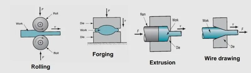
Rolling: In this process, the workpiece in the form of slab or plate is compressed between two rotating rolls in the thickness direction, so that the thickness is reduced. The rotating rolls draw
the slab into the gap and compresses it. The final product is in the form of sheet.
Forging: It is a deformation process in which the work piece is compressed between two
dies, using either impact load or hydraulic load (or gradual load) to deform it.
• It is used to make a variety of high-strength components for automotive, aerospace, and other applications. The components include engine crankshafts, connecting rods,
gears, aircraft structural components, jet engine turbine parts etc.
The workpiece is compressed between two dies containing shaped contours. The die shapes are imparted into the final part.
Extrusion: In this, the workpiece is compressed or pushed into the die opening to produce the desired crossectional shape .
Wire or rod drawing: similar to extrusion, except that the workpiece is pulled through the die
opening to take the cross-section.
Hemming : It is also a manufacturing process (mainly used in case of car Hood) which involves bending the edge of the sheet over on itself, in more than one
bending step.Thisis often done to eliminate the sharp edge on the piece, toincrease stiffness,
and to improve appearance.
JOINING PROCESS :
- Mastics are introduced between the roof outer panel and the reinforcements for joining . Where ever the mastic are introduced there is remarkable improve of the strength .
The Mastic sealant or the Mastic point is an elastic compound that behaves like a rubber. The mastic sealants are applied at the many places like roof outer to front roof rail, rear roof rail, bow roof and reinforcement center roofs. They help the roof outer panel to come back to its original shape after it gets deformed. The mastic has an influence area of 80mm.
It will give the three methods in one operation, it fills the gap between the two or more substrates, it forms a barrier through the physical properties of the sealant itself, and by adhesion to substrates.
- Spot welding is also introduced to join the reinforcements and the outer panel
CALCULATIONS
1)Heat Distortion Study On Roof :
The heat distortion study plays a major role in sheet metal usage . heat distortion temperature is a temperature limit above which the material cannot be used for the structural applications . This study is used to predict the heat distortion temperature at where the material starts to soften when exposed to a fixed load at elevated temperature . In order to avoid bending or damages on the roof, based on the heat distortion temperature , this study will predict the bow roof position which helps to strengthen the roof .
Bow–Roof Prediction Formula
W = [1.73 x 10^(-3) x L] + [1.85 x 10^(-8) x (R^2)/t] + [ 1.10x10^(-3) x l] - 2.68
Where,
L = Roof Length in X-Direction[mm](Roof dimension in 0-Y)
R = Roof curvature
R = 2(Rx*Ry)/(Rx+Ry)
Rx = X curvature
Ry = Y curvature
t = Roof plate thickness [mm]
l = Bow Roof Span [mm]
Judgment Condition
OK< 2.7
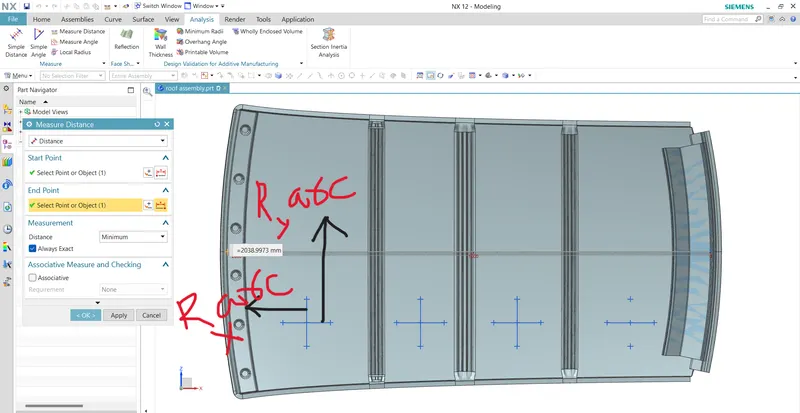
- In order to find the Heat Distortion Criteria ,apply all the necessary values from all the sections of the roof in the given formula
RESULTS
- Now the results are tabulated as follows
| Roof Rails | Rx(mm) | Ry(mm) | R(mm) | L(mm) | t(mm) | l(mm) | W(mm) | Result |
| Front Roof - Bow Roof1 | 5700.77 | 2949.22 | 3887.36 | 2038.99 | 0.75 | 522.5102 | 1.791 | PASS |
| Bow Roof1-Centre Roof | 4828.247 | 6771.763 | 5637.192 | 2038.99 | 0.75 | 294.2516 | 1.953 | PASS |
| Centre Roof-Bow Roof2 | 4039.694 | 10261.594 | 5797.199 | 2038.99 | 0.75 | 364.3426 | 2.07 | PASS |
| Bow Roof2-Rear Roof | 3305.541 | 14415.059 | 5377.86 | 2038.99 | 0.75 | 398.0740 | 1.9973 | PAS |
- From the above table it can be concluded that all values of W<2.7 and also not W >3.1 .
So thus infers that current positioning of Bow rows are good in state as per design and found ok .
2)Snow Load Criteria
This test is done to know how is the roof behaving when there is a snow over . normally due to the snow weight the dent will happen. But the roof should be designed in such a way that when the snow is removal the roof should go it its original position . This is the basic requirements for snow load criteria .
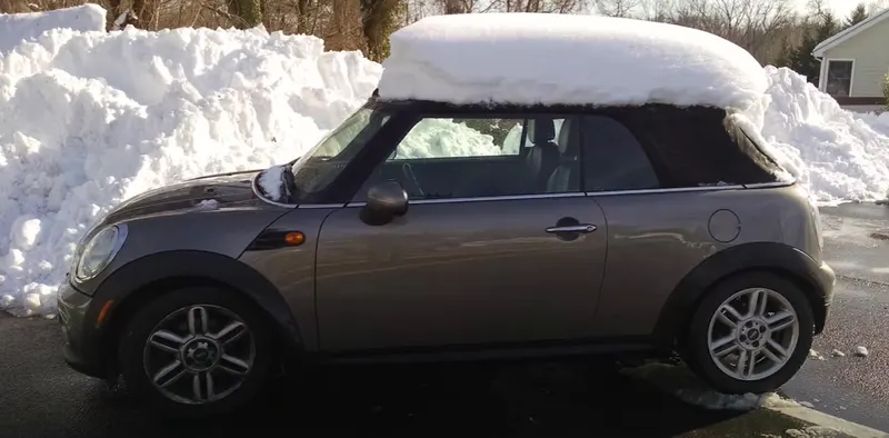
Snow Load Prediction Formula :
Qr = [Iy x t2] / [α x s x [(Rx + Ry)/2]2 x 10-8]
Where,
α = My x Lx2 x 10-12 , My = Y(Ly-Y)
t = Roof plate thickness [mm]
Ly = Distance between the front and rear roof Rails on the Vehicle along with 0Y[mm]
Length of Roof panel with the center point between Roof rail Front /Rear as the front and rear reference point.
Lx = Distance between the Left and Right end of the roof on the Roof BOW [mm]
The width of the roof panel is exposed on the surface.
Y = Distance front Front Roof Rail to Roof BOW[mm]
s = Distance for which Roof BOW bears divided load [mm]
s = L1/2 + L2/2
Iy = Geometrical moment of inertia of Roof BOW (Y cross-section )[mm4]
Rx = Lateral direction curvature radius of roof panel Y cross-section on Roof BOW [mm]
Roof panel curvature Radius of the Length Lx in Front view
Ry = Longitudinal Direction curvature radius of the Roof panel X cross-section on Roof BOW [mm]
Roof panel X curvature radius of length s in Side view
Judgment condition
Qr ≥ 3.1
250 ≤ s ≤ 380
Section Inertial Analysis:
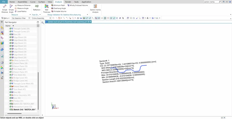
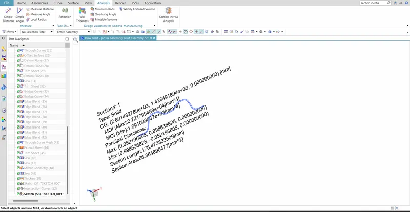
Sectional moment of inertia is used to predict the amount of deformation and deflection of a part. A higher moment of inertia is preferable as it reduces the amount of deflection for a given force. The thickness of the part and addition of flanges and embosses increase the section inertia of the part. Here the master sections of the roof and roof rails and their section analysis are given.
Front Roof Rail
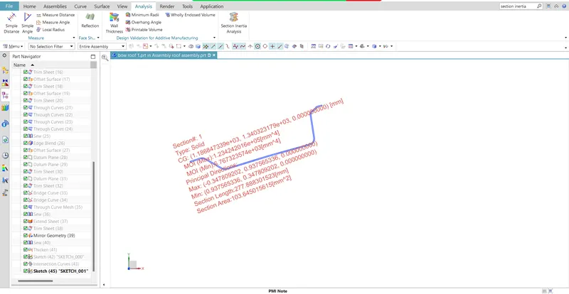
Bow Roof 1
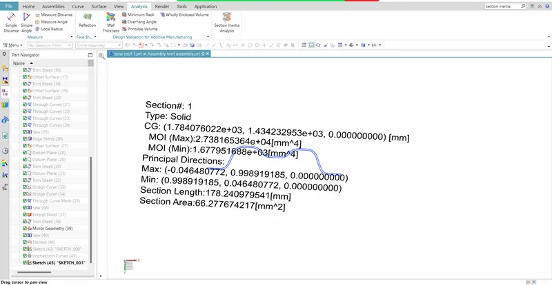
Centre Roof Rail
Bow Roof2
- In order to find the Snow Load Criteria ,apply all the necessary values including the moment of inertia using 'Section Inertial Analysis ' from possible sections of the roof in the given formula
RESULTS
Now the results are tabulated as follows
| Roof Rails |
Iy*10^3 (mm^4) |
Lx(mm) | Ly(mm) | L1(mm) | L2(mm) | Rx(mm) | Ry(mm) | t(mm) | Y(mm) | s(mm) | My(mm^2) | σ | Qr | RESULT |
| FR-BR 1 | 6.767 | 1114.7224 | 1921.078 | 591.2176 | 375.5316 | 4304.853 | 2429.084 | 0.75 | 591.2176 | 483.37 | 786232.144 | 0.976 | 71 | PASS |
| BR1-CR | 1.677 | 1114.7224 | 1921.078 | 375.5316 | 442.5011 | 5320.558 | 6720.859 | 0.75 | 966.7492 | 409.01 | 922588.98 | 1.146 | 5.55 | PASS |
| CR-BR2 | 2.229 | 1114.7224 | 1921.078 | 442.5011 | 511.8276 | 4045.8 | 10709.419 | 0.75 | 1409.25 | 477.16 | 721282.539 | 0.896 | 5.24 | PASS |
From the above table it is observed that obtained values of QR > 3.1 . Hence it satisfy the Snowload Criteria .
CONCLUSION:
- Hence the roof , front roof rail, bow roof rails , central roof rail and the rear roof rail is designed by following the master sections and the moment of inertia and draft analysis are carried out to check feasibility manufacturing.
- The roof design has satisfied both Heat distortion criteria and the Snow load Criteria