Roof Design
ROOF CHALLENGE
Objective:
For the Given Roof styling, create essential flanges and reinforcements with appropriate dimension and check for Draft analysis, Bow roof and Snow Load Prediction.
Create each part separately so that it can be assembled together in Assembly drawing.
Start with the creation of a roof ditch area the tool opening angle is only 7 degrees.
Roof:
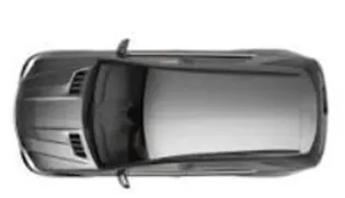
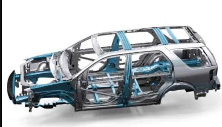
Roof of a car is structure which covers the top of the passenger compartment. It provides cover against sun, Wind, Debris etc. Also provide aerodynamics and provide visual aesthetics to the car body. It should also be structurally Rigid and should have minimum load bearing capacity for Loading on Roof Also, should protect in case of car topple over.
Types of Cars Roof:
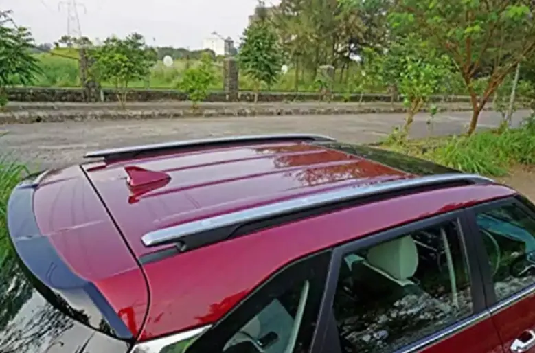
Hard Top:
A hardtop is a rigid form of automobile roof, which for modern cars is typically constructed from metal. A hardtop roof can be either fixed (i.e. not removable), detachable for separate storing or retractable within the vehicle itself.
Convertible roofs:
A convertible or cabriolet is a passenger car that can be driven with or without a roof in place. The methods of retracting and storing the roof vary among eras and manufacturers.
Convertible is of many types Hard top, Soft Top, Removable Etc.
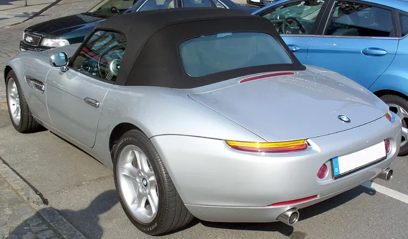
Soft Top:
Early convertibles used cotton canvas woven so tightly that it is waterproof.
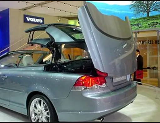
Retractable hardtop:
A retractable hardtop is a car with an automatically operated, self-storing hardtop.
The benefits of improved climate control and security are traded off against increased mechanical complexity, cost, weight, and often reduced luggage capacity.
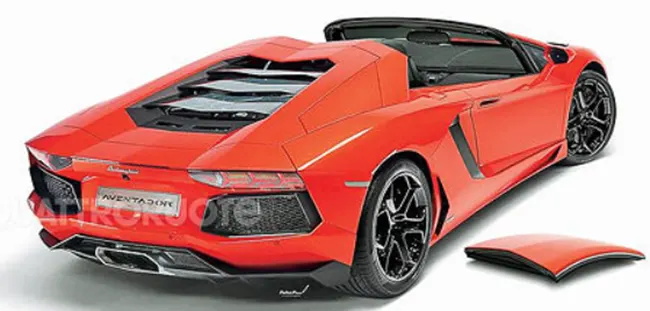
Detachable hardtop
Rigid removable hardtops, many of which store in a car's trunk/boot. These normally provide superior weatherproofing, soundproofing, and durability compared to fabric-based tops; some are available with integrated rear-window defrosters and windscreens.
Safety Standards: (Courtesy: Online Research Paper)
Safety point of view vehicle roof plays very crucial role specially roll over kind of accidents, in which vehicle tips over onto its side of roof. And vehicle rollover crashes are the causes of many fatalities and several head, neck and spine trauma around the world. Therefore, passenger safety is also very important parameter in front of OEM’s. It is not only a marketing strategy but also it is a obligation stipulated by international standards that are now place in several countries, as well as a governmental requirement.
The strength of the roof structure to occupant protection in real world rollover crashes, requiring the maximum moving distance of the roof structure should be less than 127 mm (5 in.) when the induced load is 1.5 times of the vehicle weight.
For the test the passenger car shall be rigidly placed or positioned on a horizontal surface with the doors locked and the window closed. Furthermore, a flat, rigid block with lower surface a rectangle measuring 30 inches wide by 72 inches long (762mm X 1829mm) shall not move more than 5 inches(127mm), measured as the distance between the original location of the lower surface of the test device and its location as the specified force level is reached, when it is used to apply a force of 1.5 times the unloaded vehicle weight (UVW) or 5000 lbs(22224N),whichever is less ,to either side or forward edge of the vehicle. This test can be conducted on either side of the roof structure, the front left or the front right side but not on both sides in one single test and still meet the requirements of the test. The rigid plate shall not move faster than 0.5 inches/second and the force applied on the plate shall not exceed the lesser of 1.5 times the unloaded vehicle weight (UVW) expressed in kilograms multiplied by 9.8 or 5000lbs (22240N). Also, the direction of the force shall be downward and perpendicular to the lower surface of the rigid plate and such that it moves in a straight line without rotation. Duration of the test shall not exceed 120 seconds.
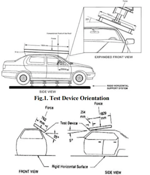
The orientation of the test device is as described below:
- The longitudinal axis of the plate is pitched forward at a 5º angle as viewed from the side of the passenger car.
- The lateral axis or the roll of the plate is such that it forms a 25º outboard angle with a horizontal surface as viewed from front of the passenger car.
- The lower surface of the plate shall always maintain a tangential contact with the surface of the roof.
- The initial point contact is 10 inches (254 mm) from the leading edge of the plate and in line with the longitudinal axis on the lower side of the plate.
Design of Roof:
Roof typical has many members such as Roof Rail, Bow Roof and Centre Roof. The arrangement changes depending upon the design such use of sun roof, Panoramic roof will have impact on number of members used.
Typically for a vehicle body includes a roof opening defined by a pair of spaced-apart side rails (Front and Rear), each having a flange extending inwardly and being vertically offset below the roof surface, and by front and rear headers, each having a flange defining a window opening.
A roof panel assembly includes a roof outer panel and reinforcement rails which underlie the outer side edges of the roof outer panel.
Outer panel is spot welded or bonded using mastic depending upon the region.
Manufacturing:
All these parts are produced by means of Stamping Process.
Master Sections:
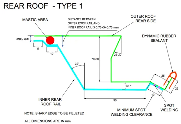
Outer Roof Panel:
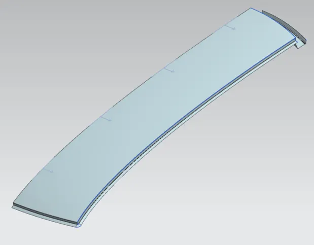
From the skin data provided, we will first create outer panel with ditch area. first create the flanges or the ditch area at the four sides with the required open angle.
Front end of the Roof need clearance for the windshield and the panel is boded together with Roof rail by Spot welding on windshield side and Mastic on the inner side.
Follow the same procedure of the rear end of the Roof panel.
Front Roof Rail:
Front Roof rail is the reinforcement for the roof outer panel and as well as it joins the Roof panel with the Windshield glass and A-pillar and also supports the bracket map lamp and room lamp mounting.
Key Parameters to be considered for Front Roof Rail design, we always keep in mind while designing the front roof we do not reduce the visibility available to driver. There should be enough space between roof rail and head position of driver so when accident will happen head will not hit to the front roof rail.
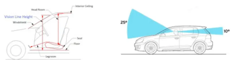
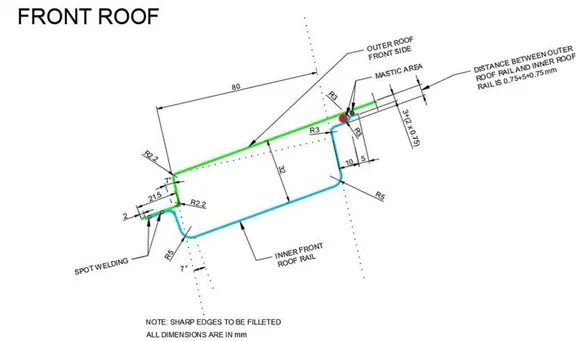
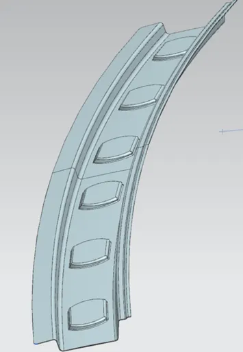
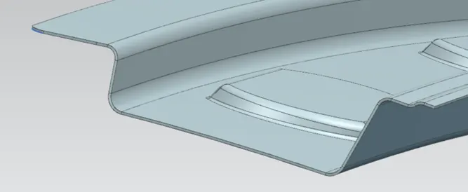
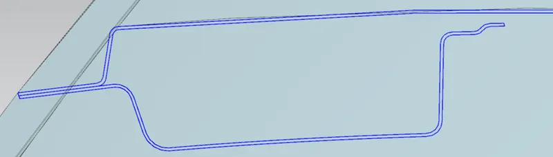
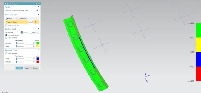
Front roof rail created based on the master section which is developed with above mentioned functional requirements of tool opening angle, required clearance for to join with the windshield glass, visibility criteria, the deepness based on the head room clearances and the clearance mastic joining. See the below master section used for the Front Roof Rail and the Front roof rail design based on the master section. Material used for this part is SP783AJQ. Selection of Materials play key role in any structure design considering factors such as tensile strength, bending, static and dynamic loading etc.
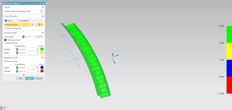
Tool opening angle of 7º is maintained.
Front Roof master with outer panel:
Drafting Analysis:
Rear Roof Rail:
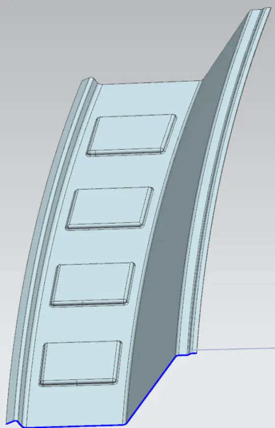
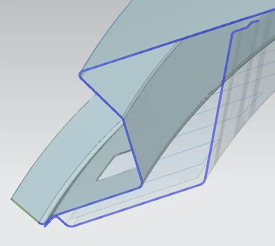
Rear Roof rail is also the reinforcement for the outer panel and it joins the backdoor and the body side outer. For designing the Rear roof rail also, we have developed a master section based on the functional requirements which are Rear visibility criteria, Rear head room clearance, Tool opening and mastic clearance.
Rear most end of Rail is spot welded with outer Roof and Inner most end of rail is bonded via mastic. Because spot weld affects visual aesthetics of the roof. Same as Front roof SP783AJQ material is used.
Drafting Analysis:
Bow roof and Centre Roof:
I have selected the combination 2 Bow Roof and 1 Centre Roof. Roof design in consideration is Hard Top roof without sunroof. So, for even Load distribution all the Bow roof and Centre roof are equally spaced at 531mm.
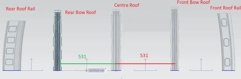
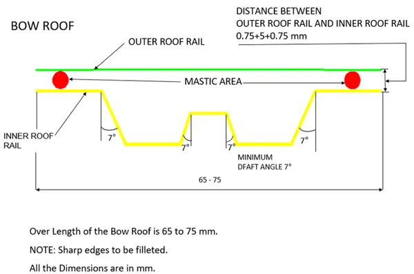
Front and Rear Bow Roof:
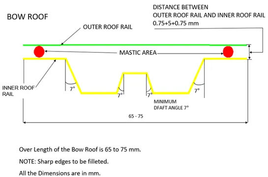
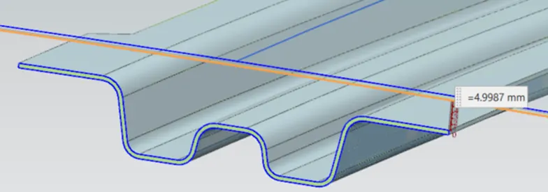
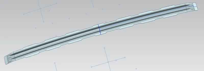
Bow roof is sheet metal component which is used to add more structural strength to the roof. On the basis of the curvature of the roof bow roof is provided.
They are joined to the Roof panel with the help of mastic sealant to the roof panel and connects to the body side using the spot-welding. Front and Rear bow roof are manufactured by SP121BQ material.
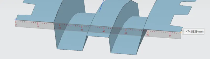
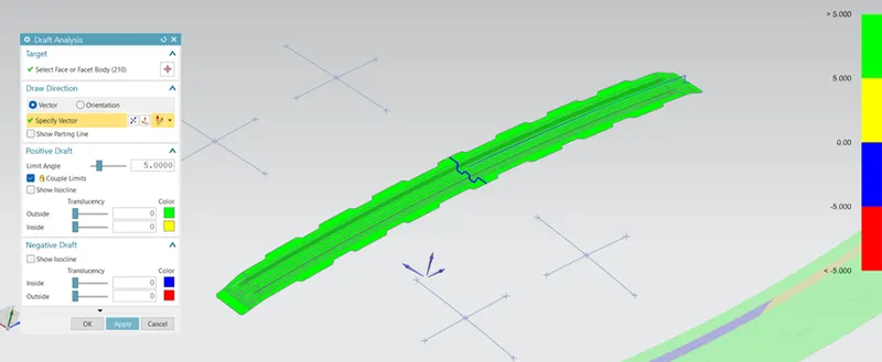
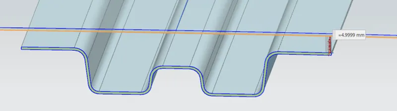
Draft angle of 7º is maintained and Maximum flange width of Bow roof is fixed at 75mm.
Front Bow Roof:
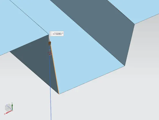
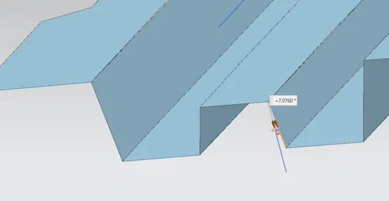
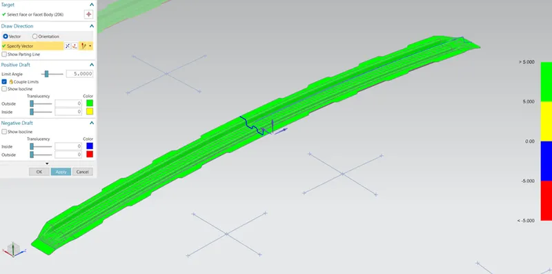
Drafting Analysis:
Rear Bow Roof:
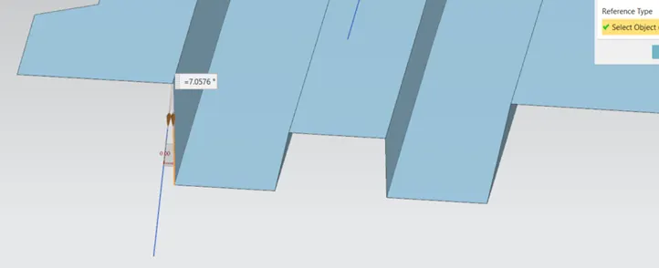
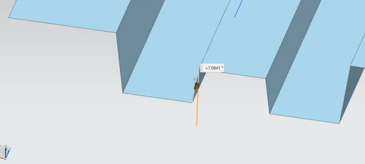
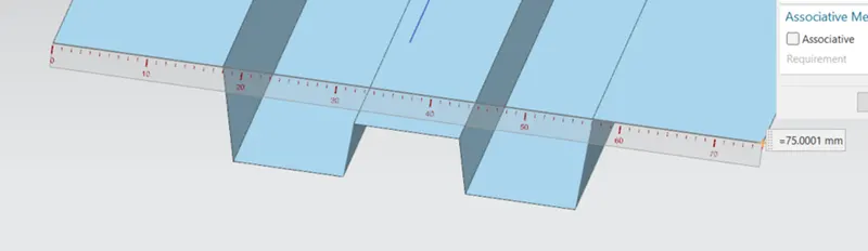
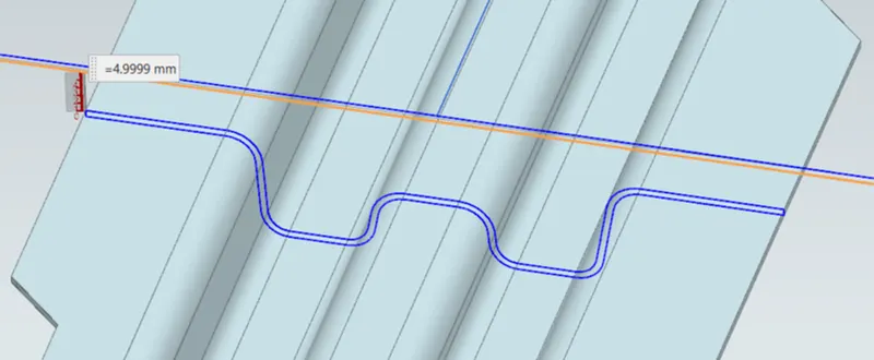

Draft Analysis:
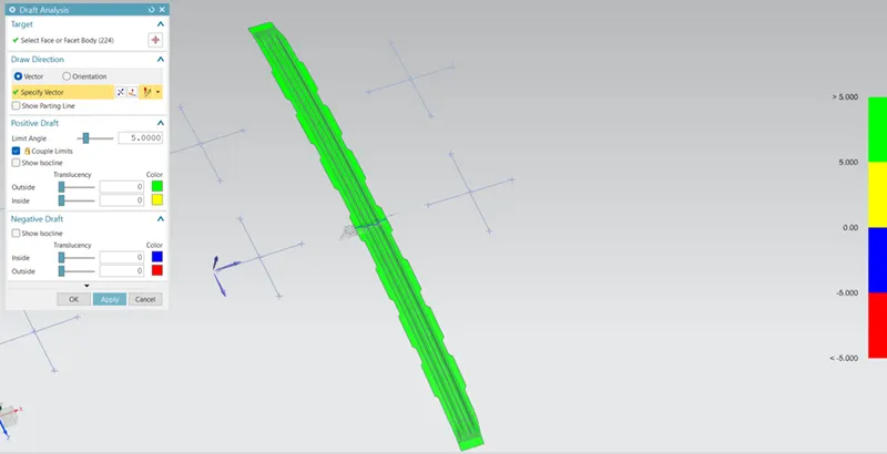
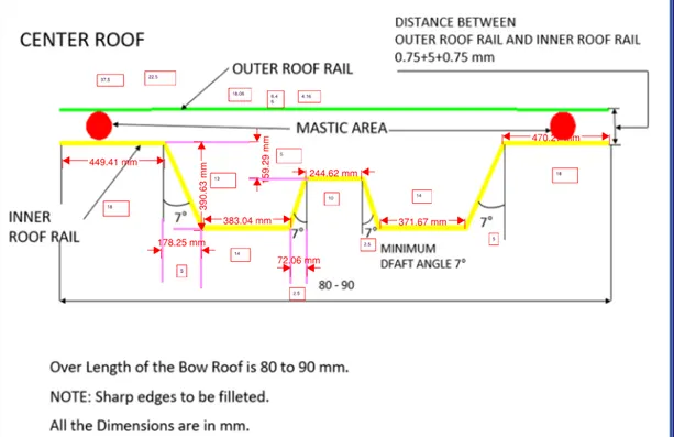
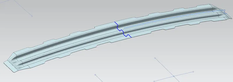
Center Roof:
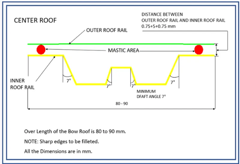
Centre Roof selection criteria. Since I choose Hard top fixed roof with out sun roof I prefer Roof without additional reinforcement. Roof panel is held with the help of mastic sealant to the roof panel and connects to the body side using the spot-welding technique. Center bow roof is made of SP153-98OPQ material.
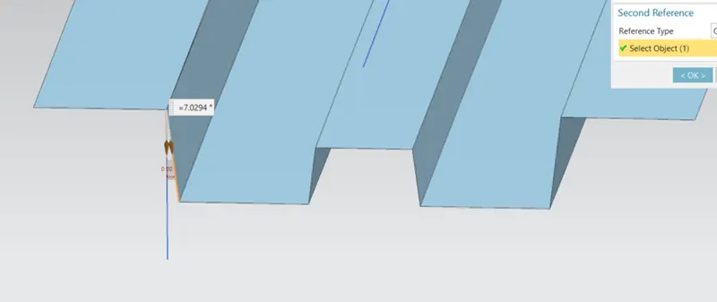
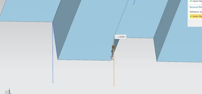
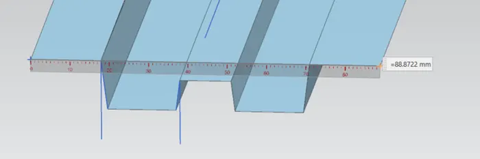
Over all width of Bow roof is 89mm. Draft angle of 7º is maintained.
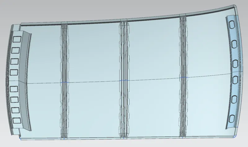
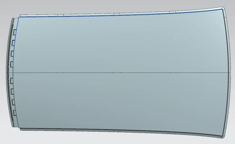
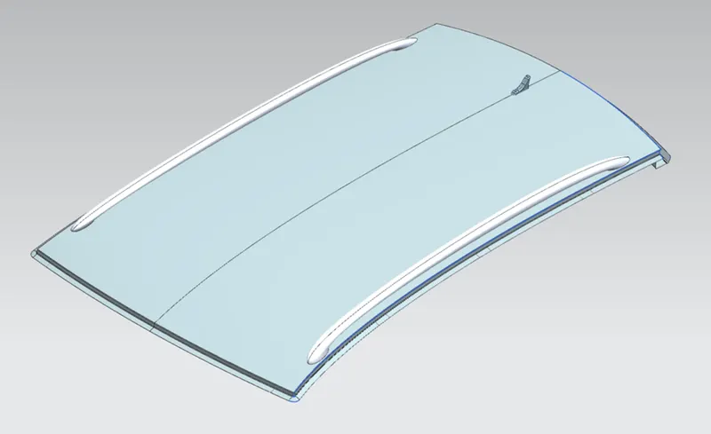
Assembled Roof:

1.Heat Distortion Criteria:
Heat distortion test is a type of static load test which plays an important role in maintaining roof strength. Heat distortion temperature is the temperature at which metal softens and deforms under a specified load.
From Heat distortion criteria, roof strength can be enhanced by appropriate positioning of bow roof rails.
Bow – roof prediction Formula:
W=(1.73×10⁻³×L) +(1.85×10⁻⁸×R2t) +(1.10×10⁻³×l) −2.68
Where AS,
L = Roof Length in X-Direction[mm](Roof dimension in 0-Y)
R = Roof curvature = 2(Rx*Ry)/(Rx+Ry)
Rx = X curvature
Ry = Y curvature
t = Roof plate thickness [mm]
l = Bow Roof Span [mm]
Judgement Condition: OK < 2.7mm ≤ NG
Procedure to calculate necessary parameters:
- Create a sketch on Assembly plane. With a new plane parallel to the Top plane.
- Create a centre line which is 0Y line. Offset the line to 300mm to form 3Y.
- Offset 3Y 100mm on both sides.
- Create a 3D point on the Intersecting line. Convert all these lines to reference lines.
- Project the points on to the surface.
- Use 3 point arc to connect the curve.
- Measure the radius to obtain Rx and Ry values.
- Over Roof length is “L” value(without ditch)
- I value with the distance between the Roof rails and Bow roof.
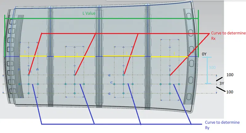
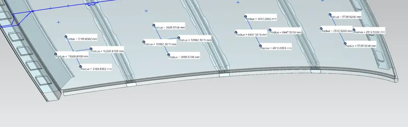
All the derived values are populated.

As per our Judgement Condition: OK < 2.7mm ≤ NG
All the values are below 2.7mm, So, the test condition is OK.
- Snow load criteria calculations
Snow load criteria is useful to justify the bow roof rail position in snow fall regions. Due to snow fall snow will get collected on the top roof which will tend to bend the roof. Bow roof will be at such position which will provide more strength to roof against bending.
Qr = [Iy x t2] / [α x s x [(Rx + Ry)/2]2 x 10-8]
Note: The Qr value given over here is correct. There was a typo error in the formula given in the video.
Where As
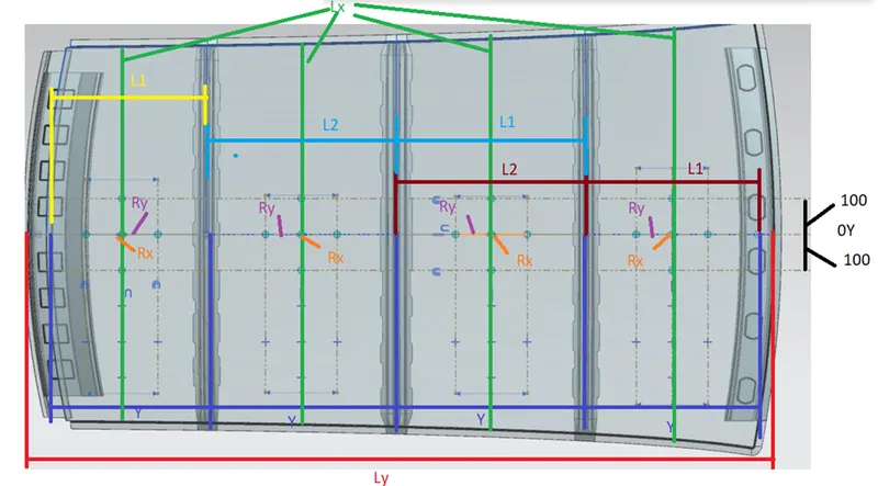
α = My x Lx2 x 10-12 , My = Y(Ly-Y)
Judgement condition = Qr ≥ 3.1
250 ≤ s ≤ 380
t = Roof plate thickness [mm]
Ly = Distance between the front and rear roof Rails on the Vehicle along with 0Y[mm]
Length of Roof panel with the center point between Roof rail Front /Rear as the reference point of the front and the rear.
Lx = Distance between the Left and Right end of the roof on the Roof BOW [mm]
Width of the roof panel exposed on the surface.
Y = Distance front Front Roof Rail to Roof BOW[mm]
s = Distance for which Roof BOW bears divided load [mm]
s = L1/2 + L2/2
Iy = Geometrical moment of inertia of Roof BOW (Y cross-section )[mm4]
Rx = Lateral direction curvature radius of roof panel Y cross-section on Roof BOW [mm]
Roof panel curvature Radius of the Length Lx in Front view
Ry = Longitudinal Direction curvature radius of the Roof panel X cross-section on Roof BOW [mm]
Roof panel X curvature radius of length s in Side view
Procedure to calculate necessary parameters:
- Create a sketch on Assembly plane. With a new plane parallel to the Top plane.
- Create a centre line which is 0Y line.
- Offset 0Y line 100mm on both sides.
- Create a 3D point on the Intersecting line. Convert all these lines to reference lines.
- Project the points on to the surface.
- Use 3 point arc to connect the curve.
- Measure the radius to obtain Rx and Ry values.
- Over Roof length is “Ly” value(without ditch)
- y value with the distance between the Roof rails and Bow roof.
- Lx will span of each Bow roof.
- L1 and L2 will distance between front Roof rail to front bow roof and Front bow roof to center boof row is first value. 2nd value will Front bow roof to center boof row and center boof row to rear bow roof. 3rd value will be rear bow roof to Rear roof rail is L1 value. There is no L2 value.
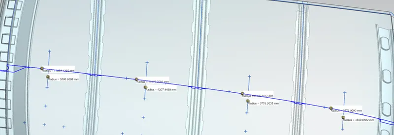
Inertia of Front Bow Roof
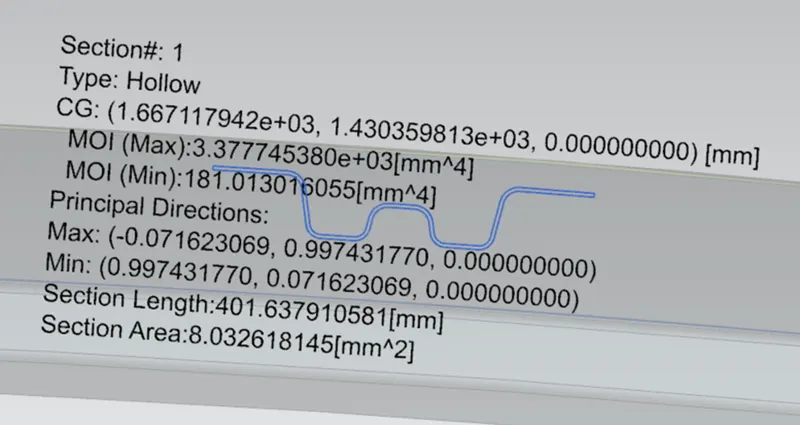
Inertia of Centre Bow Roof
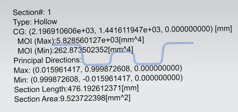
Inertia of Rear Bow Roof
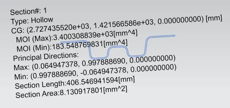
All the values are populated

From the values
Judgement condition:
Qr ≥ 3.1 – Not Satisfied
250 ≤ s ≤ 380 - Not Satisfied
Solution:
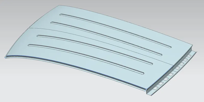
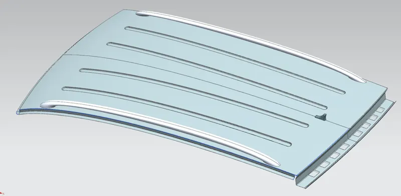
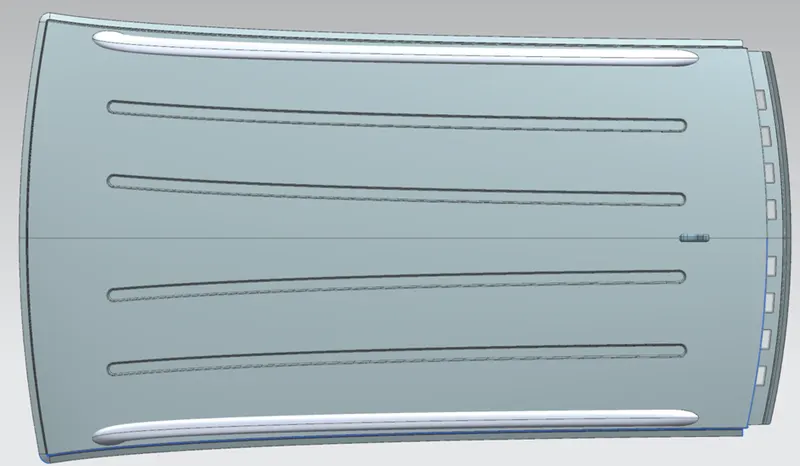
Since the values show the roof is structurally stable. We need a solution to fix the issue. We will be adding additional embosses to provide additional strength to the Roof. Will there by satisfy the Snow load test.
Here is the Redesigned roof with Embosses,
CONCLUSION
The Roof and its reinforcements were designed successfully according to their master sections and criteria’s
The Heat Distortion Criteria was fulfilled
The Snow Load Criteria was not fulfilled, thus the design needs improvement, hence suggestion is provided in the form of embosses.
The Draft analysis was also performed and the parts are found to be feasible for manufacturing process.