Hood design-Week 2
Design and Assembly of Hood
Aim:
To design an inner panel of a hood following the design constraints provided, Outer panel is provided from which the inner panel is designed to meet the design criteria. Let us see what are al the integral part of the hood, Standards and Steps to design.
HOOD:
It is basically an outer cover of the engine compartment. It provides good aesthetics to the car’s front, without compromising the structural integrity. There are lot of safety guidelines to meet the crash worthiness both for the car and the pedestrian safety. It should contain the crash within the engine bay area.
The design should be less complicated which should not have manufacturing difficulties (Stamping) and also during maintenance. Proper height of hood opening depending on the region
Proper finger gap for the region. Then the position of the hinge and striker without affecting the other components position or their service requirements and proper positioning of support rod.
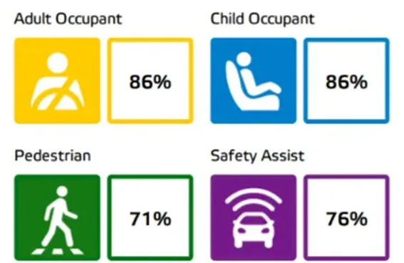
Passenger safety is important similarly pedestrian safety is very much. Almost million people killed in Road accidents annually bigger percent of them are pedestrians. Most fatalities of pedestrians met with head injury cause by impact of the head on the hood. The Government hasn’t overlooked pedestrian safety and has issued a notification which mentions that apart from passing these impact tests, the external panels on new cars will have to be designed in a way that minimizes injury, in the unfortunate event of a pedestrian being hit. Government organisations such as EURONCAP, GLOBALNCAP. ASEANCAP drew guidelines to ensure pedestrian safety.

They conduct tests on almost on all new cars and provide crash test rating. European government made it mandatory to crash test all cars to sell from October 2017.
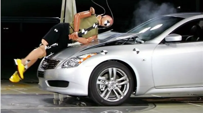
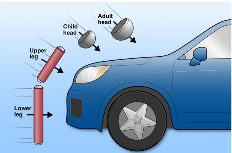
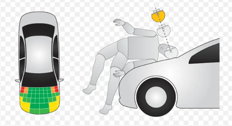
Pedestrian who involves in crash usually have impact on a moving while walking or standing still. Impact is created on the pedestrian twice. Frist on the body of the car and second after the impact they hit on the ground. Most fatal injuries occur due to impact on the car first. Vehicle designers drew multiple scenarios involving the pedestrian and car impact. The vehicle bumper first contacts the lower limbs of the pedestrian, the leading edge of the hood hits the upper thigh or pelvis, and the head and upper torso are struck by the top surface of the hood.
Guidelines for Pedestrian impact zones
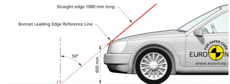
- The side line the first point of contact of a line drawn 45 deg from the floor and there are two types of hoods based on the side line they are Inlaid hood and Wrap around hood.
- The impact zone is split into three areas they are leg impact zone, pelvis region, adult head impact and child head impact zones.
- The better the soft spots in the head impact zones the better will be the safety standards and rating from NCAP.
- Adult head impact distance from front-1500mm
- Child head impact distance from front-2100mm]
Objective:
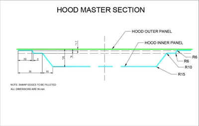

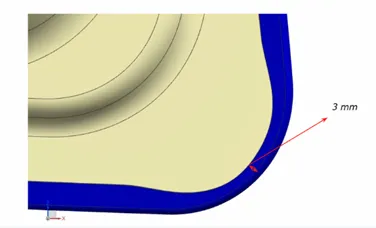
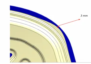
With the master data provided we need to design the inner panel, Outer panel,
Assembly the outer and inner panel and provide hemming Assemble together with the hinge and striker assembly.
Create constraints for Hinge and set trajectory for the striker and provide constraint.
Parts involved in Hood:
- Support Rod
- Inner Panel
- Outer panel
- Hinge assembly
- Striker
- Support Rod:
When a hood is opened it held in place to carry out maintenance. It is done in either of 2 way.
- Gas Stay
- Support Stay
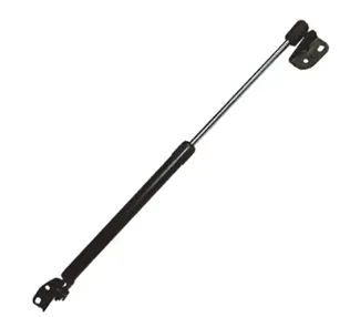
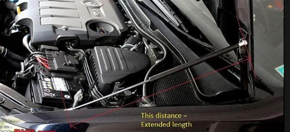
Gas stay is type of support when a hood is opened it stay in place. It is mostly used for cars with much heavier hoods, because gas stay makes use of Pneumatic actuators to stay in place.
Support Stay
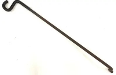
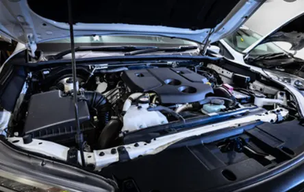
For support stay as the name suggests, the Support is held on position with the mount provided in the engine bay area, or in the bonnet for upside down type. It is use in most of the small cars and it is cost effective.
- Outer Panel:
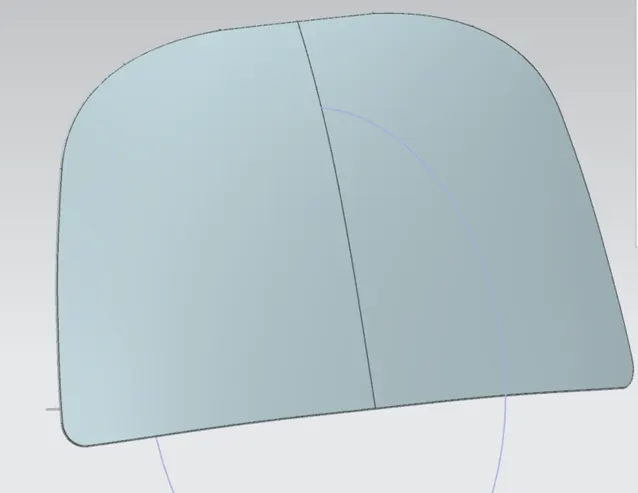
The outer panel of the hood is the coverage for the inner panel, it is mated with the inner panel by the process of hemming. It is the first part of the Design it is offset to create inner panel.
Outer panel is the key attraction point of any car. It should be visually appealing but maintaining its structural integrity.
Surface should be streamlined with very less drag co-efficient which will have direct impact of performance of car.
Process involved in manufacturing Inner panel are
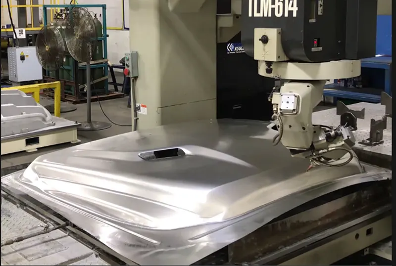
- Stamping:
Plane sheet metal is kept into mould die (Hydraulic or Pneumatic). Panel is cut into desired shape.
- Hemming:
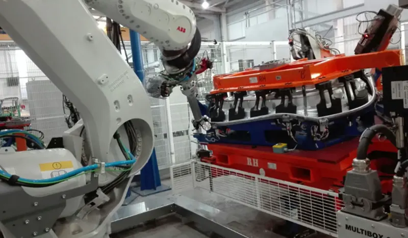
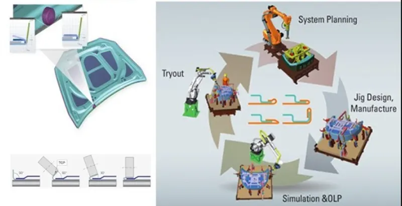
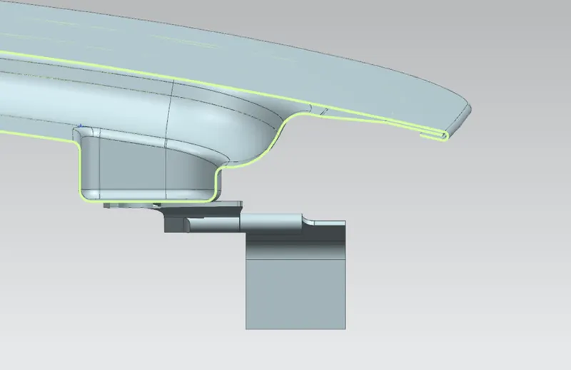
Hemming is a metal working process in which a sheet metal is folded over onto itself.
Normally hemming operations are used to connect parts together, to improve the appearance of a part and to reinforce part edges.
This process eliminates the need for welding, it will impact of material properties due to heating and adds to weight.
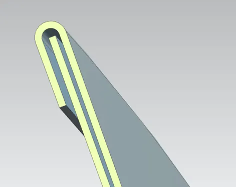
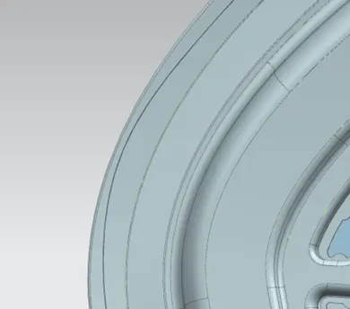
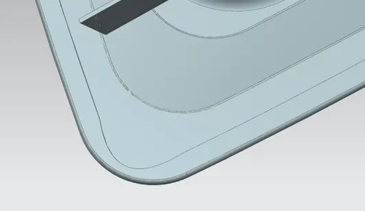
Hem flanges are protected by a sealant to prevent crevice corrosion of the sandwiched metal. In principle, the hemming technique produces sufficiently strong mechanical joints around the periphery of closure panels When force is applied during hemming process there may be a change of shape which is examined, and relaxation is given in those areas to decrease the stress concentration.
Hemming:
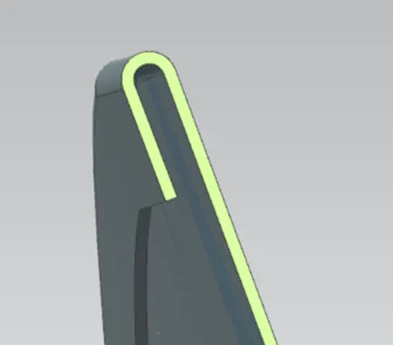
Hemm Clearance:
Relief ares at sharp edges:
- Inner Panel:
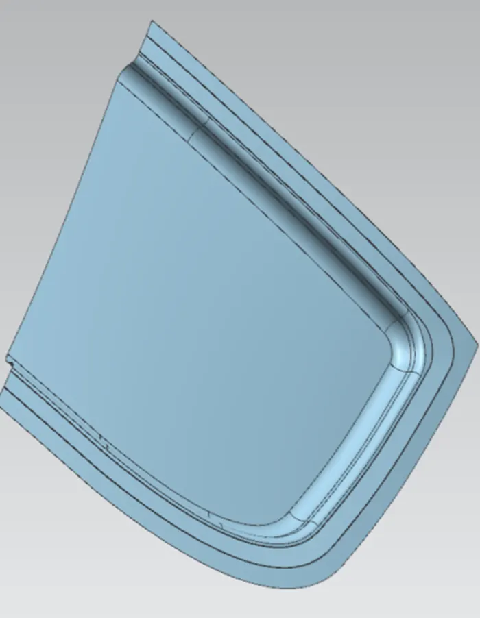
To design an inner panel, we need to offset the outer panel. This will act as a reference surface for the inner plane. First offset is done based on master section data provided.
Trim the surface and Create law extension of the curve.
Trim and extend the surface based on the offset surface provided.
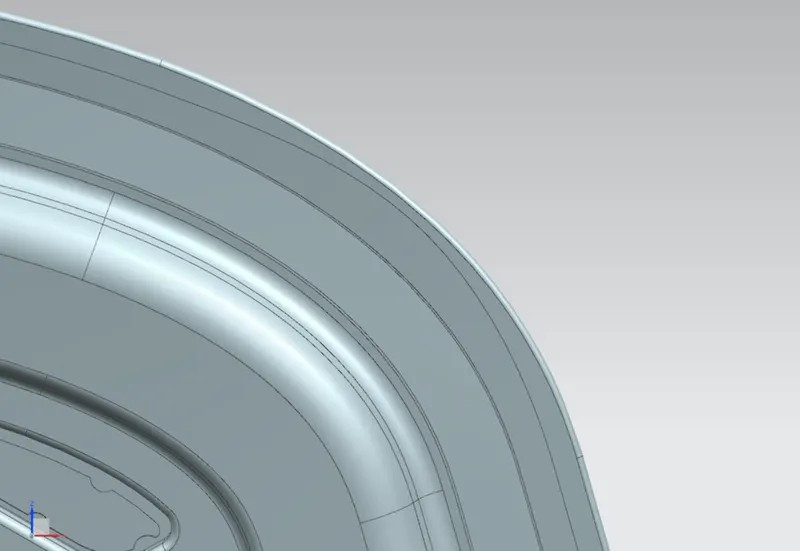
Provide face blends and edge blends to achieve the desired shape.
Emboss:
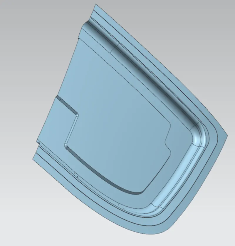
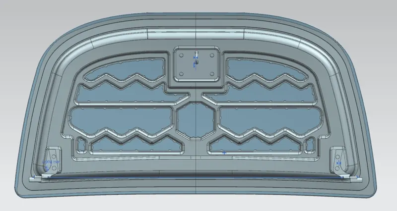
Then we need to create the embosses. The design of embosses are done in accordance with the force distribution of frontal impact, it is designed in such a way that the reduction of force starts when it is directed till the corner.
This will be tested by the CAE team once the designer provides the CAD model for testing.
Final Emboss:
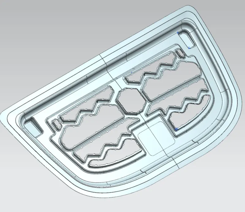
The Zone near the turn and latch has more chances of more stress in the hood panel. Consequently, to avoid any failure to rotate and latch region upheld with extra materials whose thickness is regularly directed by the sort of the vehicle.
Reinforcement:
The reinforcements give additional strength to inner panel of the centres where various parts for instances, the lock and rotate will be put. The reinforcement ensures that the turns and the snare have better assistance to avoid frustration.
Reinforcements are enabled for compensating the loss of material or the structure strength locally. The reinforcements can be given in different forms. Even the inner panel is a type of reinforcement for the outer panel. The thickness of reinforcements was about 1 to 1.5mm. Here 1.5mm thickness reinforcements used. This value of reinforcements has to pick up from CAE team as loss compensation feedback.
Mastic points:
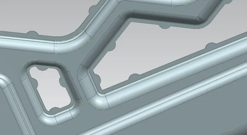
The main purpose of using mastic sealant is to adhere two surfaces, the outer panel and inner panel. Although a hemming joining process is performed the mastic sealant makes the two panels to adhere rigidly.
Between the reinforcement mastic regions are provided.
This is sealant basically a glue which expand when heated and stiffens after coming out of the dry chamber for ED coating.
It makes the inner compartment of panel as air tight towards corrosive fluids. The sealants were applied with no dripping on the specified location. The applied vicinity of the drop is about 80mm. This seal covers almost all the area between inner and outer panel.
Assembly:
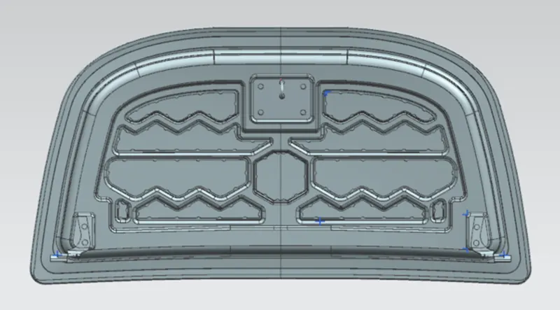
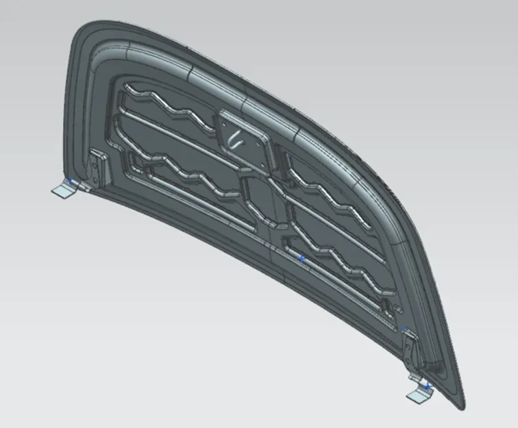
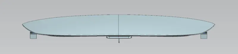
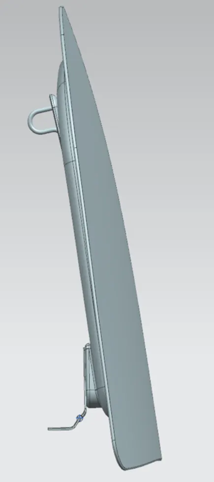
First step is to fix the position of outer and inner panel are designed using it as a reference and doesn’t need any constrains.
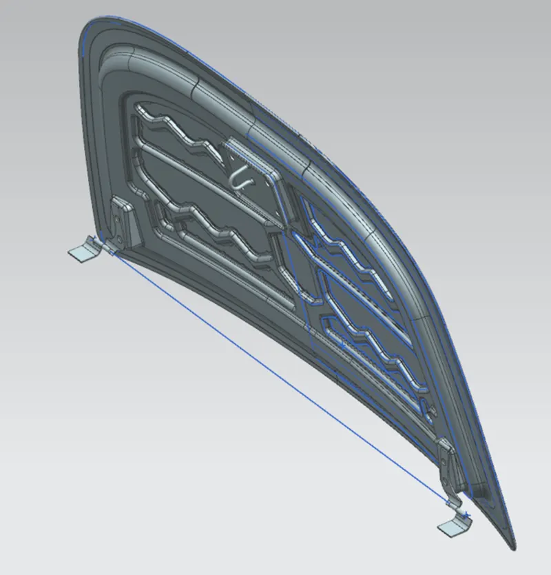
The objective to position the hinge and striker with respect to each other with specified rules.
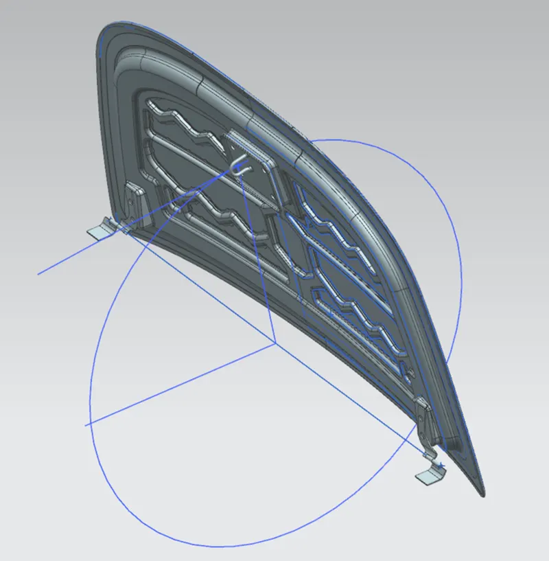
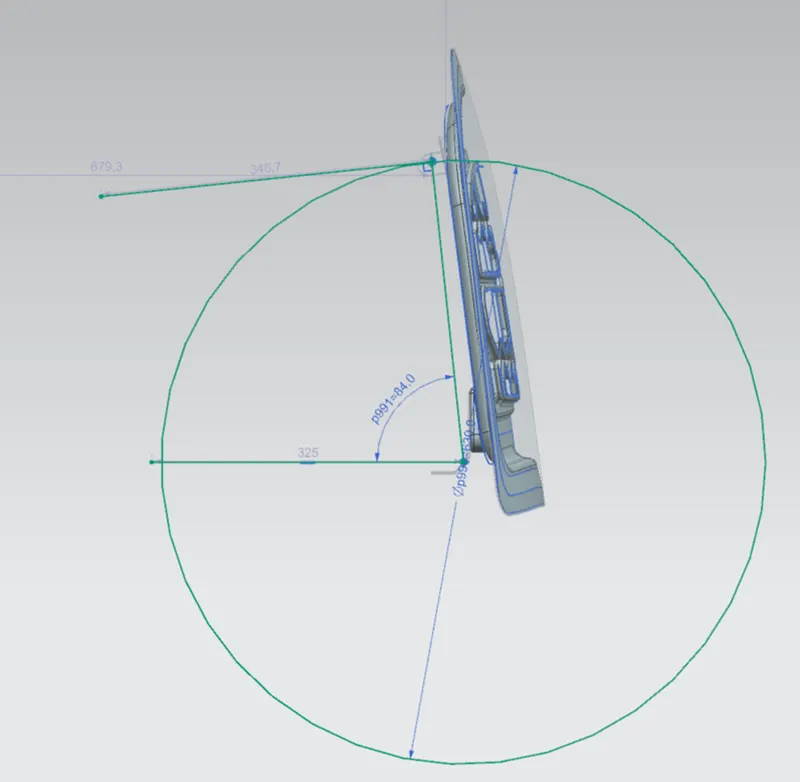
The rule is to draw a line between the centre point between two hinge and a circle is drawn from midpoint of the line for striker position, draw another line tangential to Circle.
At first the single hinge is positioned with making hinge centre line parallel to x axis and the engine part of hinge yz plane is made parallel with the yz of the assemble
Then a distance constrain of 2mm is created and then new component of hinge
The hinge is then mirrored with associative and copied constraints.
reinforcement is created using the reference surface from the hinge assembly and is also made associative and doesn’t require and constrain and is also mirrored with the associative option
A point is created in between the hinges and a circle.
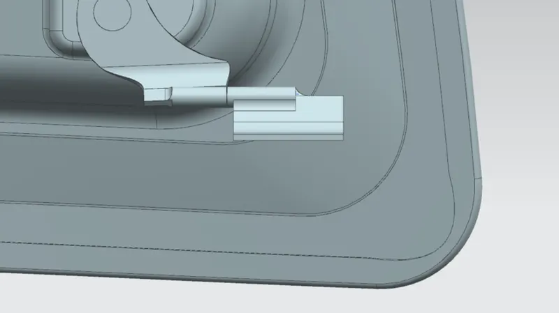
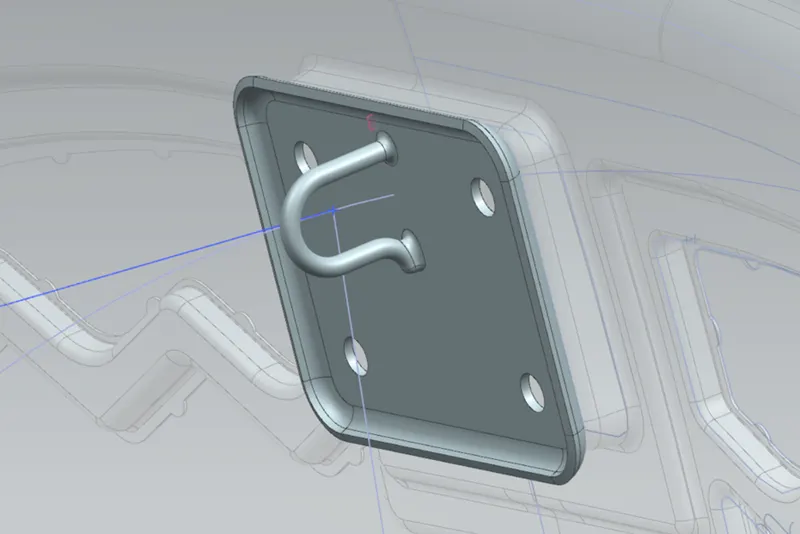
Open striker and create a plane intersection the striker in the middle. Create a sketch on the line parallel to the tanget line drawn before.
The striker where first a mid plane of yz is made aligned with the mid plane of the yz of assembly
Now we apply necessary constraints to bring them to position
Open Assembly constraints in assembly tab, lines of the striker and the circle are made touch align Constraint.
Striker is moved to the required ergonomic position then and reference surface is taken into the inner panel.
It is done with the help of wave geometry linker, then this reference used to create the embossed plane and sketch for the striker placement in the inner panel.
then a distance alignment of 2mm is give and finally the striker reinforcement is created using the reference of the constrained striker.
Conclusion:
We have created the inner panel with respect to provided master data and assembled with the provided striker and hinge assembly.