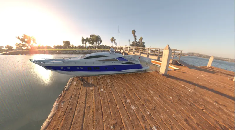
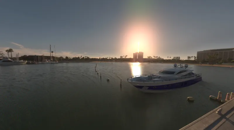
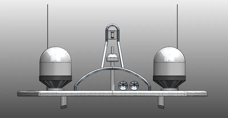
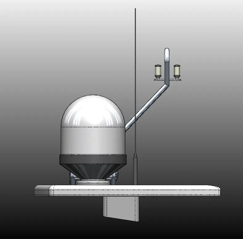
Radar Mast & Final Assembly of Yacht
3D MODELING, ASSEMBLY AND RENDERING OF SUNSEEKER YACHT
- OBJECTIVE:
To create a Yacht Model, Each component is modelled using Solidworks. It is then assembled and Rendered in Solidworks and Finally Photo Realistic Rendering is performed in Solidworks visualize. Understanding the tools and Features of Solidworks.
- INTRODUCTION:
In this project we will be learning skills sets required to Model Sunseeker Yacht in Solidworks. We will be starting from scratch i.e from Sketch to till Photo Realistic Render.
- DESIGN METHODOLOGY/APPROACH:
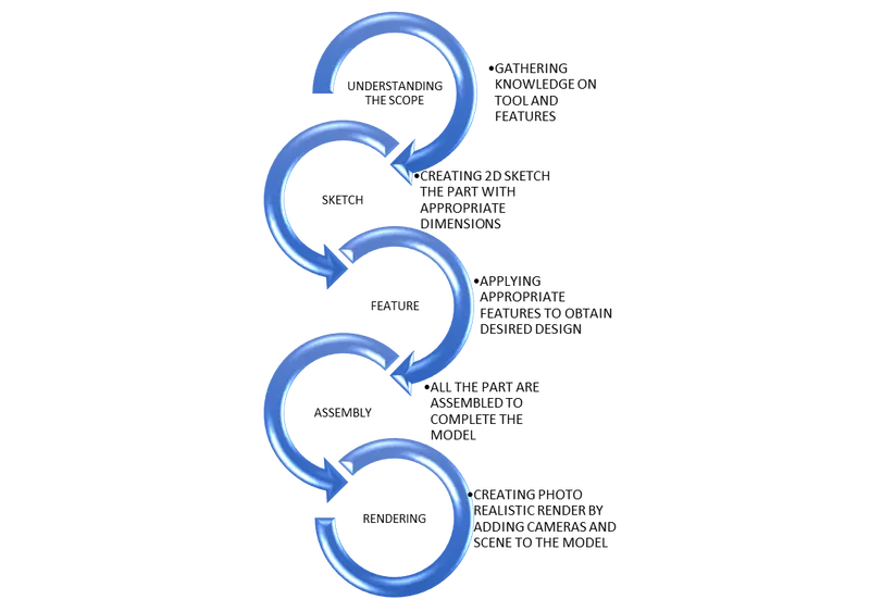
We will be developing the model in a part-by-part basis. Each part is designed individually from dimensionally constraint 2D sketches and then converted 3D bodies. Unlike American chopper model we will be using more Surface features in this model. The developed parts are assembled to create a complete model. Approach to modelling the Yacht model as follows:
Components to be Modelled for Yacht:
- Propeller
- Radar
- Hull
- Garage door
- Super Structure
- Front Seat
- Middle Seat
- Rear Seat
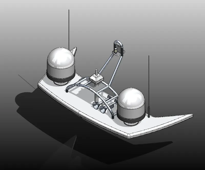
- Radar Mast
- DESCRIPTION: Tools/ Features used to design the Part files.
First and foremost, step for all the 3D modelling in Solidworks is to create a template. It should be done before beginning the project.
In this stage required parameters are set such as the drawing units (Millimetre, gram, second or meter, kilogram, second). Rename reference plane, so that whenever new part is created, we use this template for reference.
BLUE PRINT SETUP:
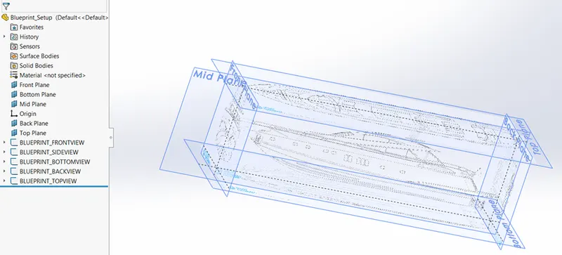
Before creating a model, we will be importing blue print of the actual scale model. We will be creating a separate plane for each and every view with their corresponding Blueprint images. We will be added
- Blueprint Front view.
- Blueprint Side view
- Blueprint Bottom view
- Blueprint Back view
- Blueprint Top View
- Propeller:
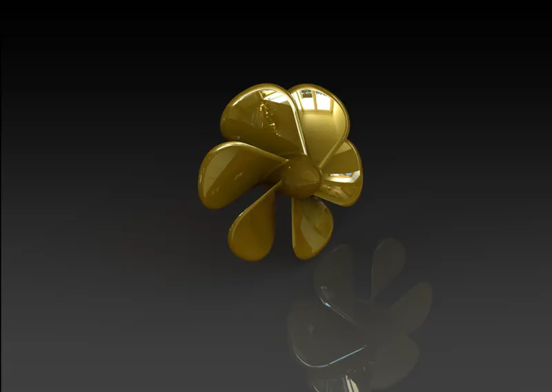
Propeller is a crucial part for a boat or Yacht, as the name suggest it propels the Yacht forward.
First step is to select the template which we have created for the course. Then required Plane selection is identified. It is will help us identify the plane for easy assembly.
Tools/ Features:
Tools and features used: Line, Dimension, Revolved Boss/Base, Lofted Boss/Base, Extruded cut, Fillet and Pattern
Steps:
- Revolved Boss/Base - To create a solid feature, a sketch or it is selected contours are revolved with axis.
- Lofted Boss/Base - Used to create a solid out of Two sketch profiles.
- Fillet - It is used to smoothen the sharp edges to desired radius.
- Extruded Cut - It is used to a cut hole on any solid to desired depth and shape.
- Pattern - To replicate the created part with the specified path and count.
- Radar:
It is used detect the obstacles within the specified radius.
Tools/ Features:
Tools and features used: Extruded Boss/Base, Fillet, Extruded Cut, Sketch Driven Pattern, Mirror and Split line.
Steps:
- Extruded Boss/Base - It is used to a 2D sketch into 3D at desired depth. It is possible only when the sketch is closed.
- Fillet - It is used to smoothen the sharp edges to desired radius.
- Extruded Cut - It is used to a cut hole on any solid to desired depth and shape.
- Sketch Driven Pattern - To create a pattern of a feature, Face or Body based on sketch points.
- Mirror - Mirror the desired body, face or feature with reference to centre line, axis, face or plane.
- Split Line - Used to project a sketch to curved or faces and create separate face based on the sketch.
- Hull:
Hull is main structure of any part of the boat or ship. It holds the crucial cargo, Engine also main load bearing structure.
Tools/ Features:
Tools and features used: Projected curve, Lofted surface, Trim surface, Extruded surface, Knit surface, Surface Fill, Shell, Extruded Boss/Base, Extruded cut, Fillet, Chamfer, Plane, Swept Boss/Base, Revolved Boss/Base, Dome, Helix and spiral, Linear pattern, 3d sketch, Mirror and Split Line
- Projected Curve - Project the sketch from 2 different planes to form a single curve.
- Lofted Surface - Create a surface from two or more profile.
- Trim surface - Trim a surface based on profile, or trim the intersecting surface.
- Extruded Surface - Create a surface based on the sketch.
- Knit surface - Combine two or more adjacent surfaces.
- Surface Fill - Create a surface path within a closed boundary.
- Shell - Create a thin wall of desired thickness, from a solid body
- Extruded Boss/Base - It is used to a 2D sketch into 3D at desired depth. It is possible only when the sketch is closed.
- Extruded Cut - It is used to a cut hole on any solid to desired depth and shape.
- Fillet - It is used to smoothen the sharp edges to desired radius.
- Chamfer - Similar to fillet, this feature helps to create a bevel of desired distance on a intersecting edges.
- Plane - A reference plane is added based on the selected reference either a plane, sketch or reference point.
- Swept Boss/Base - Sweep any closed profile along a selected path to form a 3D solid.
- Revolved Boss/Base - To create a solid feature, a sketch or it is selected contours are revolved with axis.
- Dome - This creates a dome shape to selected face.
- Helix and spiral - Add a helix or spiral curve from a sketched surface.
- Linear pattern - It creates a pattern of feature, face or body along a selected path or axis.
- 3D sketch - Creates a new 3D sketch in a working plane
- Mirror - Mirror the desired body, face or feature with reference to centre line, axis, face or plane.
- Split Line - Used to project a sketch to curved or faces and create separate face based on the sketch.
- Save Bodies - Save or extract a body into to a separate part file.
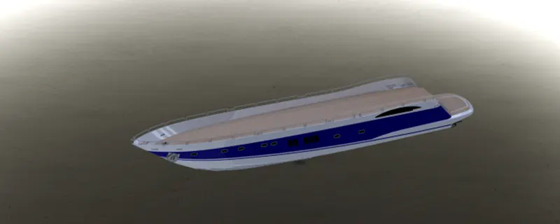
- Garage Door
Tools/ Features:
Tools and features used for Garage door, Open the saved Garage door file.
- Extruded Cut - It is used to a cut hole on any solid to desired depth and shape.
- Shell - Create a thin wall of desired thickness, from a solid body
- Fillet - It is used to smoothen the sharp edges to desired radius.
- Mirror - Mirror the desired body, face or feature with reference to centre line, axis, face or plane.
- Plane - A reference plane is added based on the selected reference either a plane, sketch or reference point.
- Front Seat
Tools/ Features:
Tools and features used: Plane, Swept Surface, Extruded Surface, Trim surface, Surface Fill, Lofted surface, Knit surface, Chamfer, Revolved Boss/Base, Extruded Cut, Fillet, Mirror, Dome
Steps:
- Plane - A reference plane is added based on the selected reference either a plane, sketch or reference point.
- Swept Surface - Creates a surface by sweeping closed profile along a reference path
- Extruded Surface - Create a surface based on the sketch.
- Surface Fill - Create a surface path within a closed boundary.
- Trim surface - Trim a surface based on profile, or trim the intersecting surface.
- Lofted Surface - Create a surface from two or more profile.
- Knit surface - Combine two or more adjacent surfaces.
- Extruded Cut - It is used to a cut hole on any solid to desired depth and shape.
- Fillet - It is used to smoothen the sharp edges to desired radius.
- Chamfer - Similar to fillet, this feature helps to create a bevel of desired distance on a intersecting edges.
- Revolved Boss/Base - To create a solid feature, a sketch or it is selected contours are revolved with axis.
- Dome - This creates a dome shape to selected face.
- Mirror - Mirror the desired body, face or feature with reference to centre line, axis, face or plane.
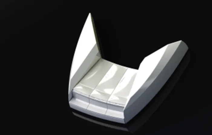
- Middle Seat
Tools/ Features:
Tools and features used: Extruded Boss, Plane, Chamfer, Fillet and Mirror
Steps:
- Extruded Boss - Extrude the sketch to desired length. Draw another sketch in Mid pane and Extrude.
- Plane - A reference plane is added based on the selected reference either a plane, sketch or reference point.
- Fillet - It is used to smoothen the sharp edges to desired radius.
- Chamfer - Similar to fillet, this feature helps to create a bevel of desired distance on a intersecting edges.
- Mirror - Mirror the desired body, face or feature with reference to centre line, axis, face or plane.
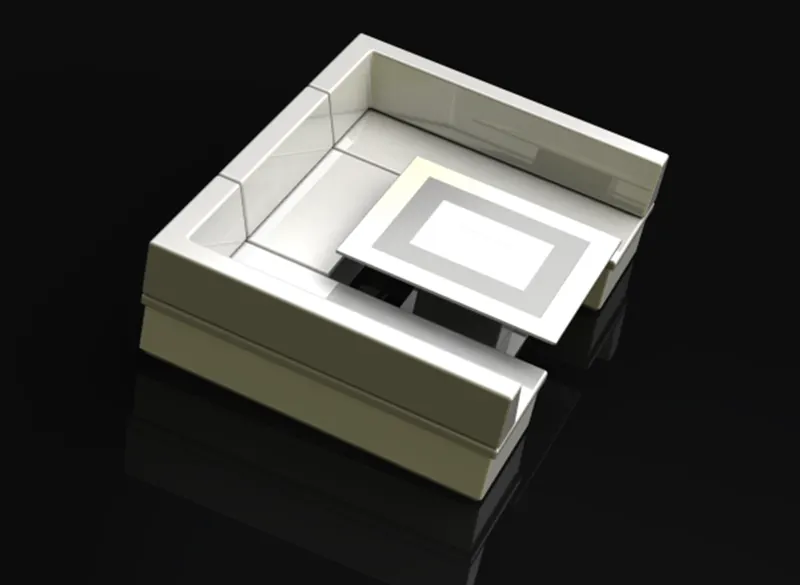
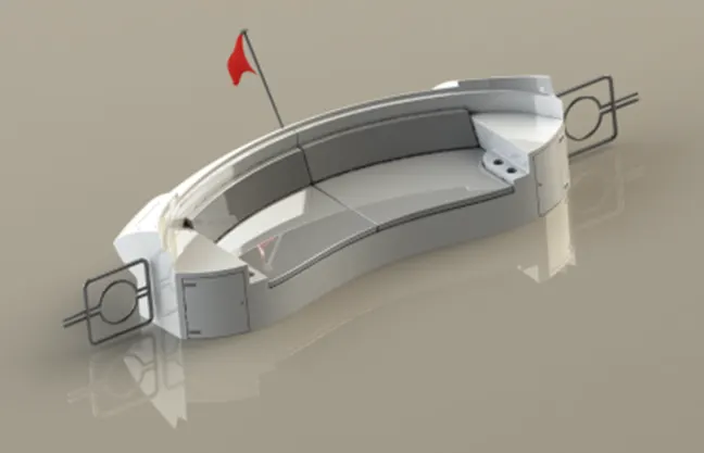
- Rear Seat
Tools/ Features:
Tools and features used: Plane, Swept Surface, Offset surface, Trim Surface, Ruled Surface, Knit surface, Lofted Surface, Extruded Surface, Extend surface, Combine, Extruded cut, Chamfer, Extruded Boss/base, Fillet, Mirror, Revolved Boss/Base.
Steps:
- Plane - A reference plane is added based on the selected reference either a plane, sketch or reference point.
- Swept Surface - Creates a surface by sweeping closed profile along a reference path
- Offset surface - Create a offset of an exsiting surface
- Trim surface - Trim a surface based on profile, or trim the intersecting surface.
- Ruled Surface - Insert ruled surface from the edges.
- Knit surface - Combine two or more adjacent surfaces.
- Lofted Surface - Create a surface from two or more profile
- Extruded Surface - Create a surface based on the sketch.
- Extend surface - Extends the edge, multiple edges or the face on a surface, based on end conditions and extension type.
- Combine - This feature combines two or more solid bodies together.
- Extruded Cut - It is used to a cut hole on any solid to desired depth and shape.
- Fillet - It is used to smoothen the sharp edges to desired radius.
- Chamfer - Similar to fillet, this feature helps to create a bevel of desired distance on a intersecting edges.
- Extruded Boss - Extrude the sketch to desired length. Draw another sketch in Mid pane and Extrude.
- Mirror - Mirror the desired body, face or feature with reference to centre line, axis, face or plane.
- Revolved Boss/Base - To create a solid feature, a sketch or it is selected contours are revolved with axis.
- Super Structure
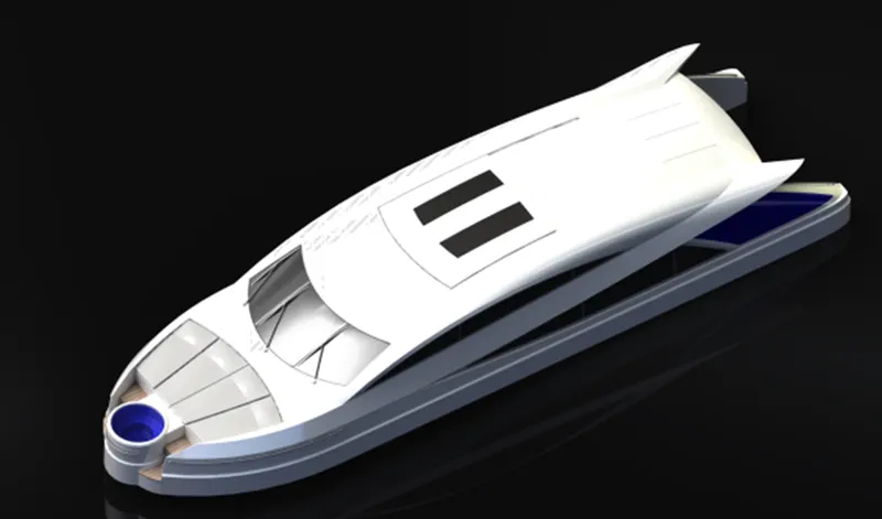
Tools/ Features:
Tools and features used: Extruded Surface, Plane, Swept Boss/Base, knit surface, Fillet, Ruled surface, Trim Surface, Projected Curve, Lofted curve, Filled surface, 3D sketch, Extend surface, Extruded Boss/Base, Extruded cut, Delete Face, Offset surface, Thicken, Dome, Split line, Mirror, Chamfer, Split
Steps:
- Extruded Surface - Create a surface based on the sketch.
- Plane - A reference plane is added based on the selected reference either a plane, sketch or reference point.
- Swept Boss/Base - Creates a surface by sweeping closed profile along a reference path
- Knit surface - Combine two or more adjacent surfaces.
- Fillet - It is used to smoothen the sharp edges to desired radius.
- Ruled Surface - Insert ruled surface from the edges.
- Trim surface - Trim a surface based on profile, or trim the intersecting surface.
- Projected Curve - Project the sketch from 2 different planes to form a single curve.
- Lofted Surface - Create a surface from two or more profile
- Surface Fill - Creates a patch within a boundary
- 3D sketch - Creates a new 3D sketch in a working plane
- Extend surface - Extends the edge, multiple edges or the face on a surface, based on end conditions and extension type.
- Extruded Boss - Extrude the sketch to desired length. Draw another sketch in Mid pane and Extrude.
- Extruded Cut - It is used to a cut hole on any solid to desired depth and shape.
- Delete Face - Delete faces from solid bodies to create surfaces
- Offset surface - Creates offset surfaces using one or more adjoining faces.
- Thicken - Creates a solid out of surface with desired thickness
- Dome - This creates a dome shape to selected face
- Split Line - Used to project a sketch to curved or faces and create separate face based on the sketch
- Chamfer - Similar to fillet, this feature helps to create a bevel of desired distance on a intersecting edges.
- Mirror - Mirror the desired body, face or feature with reference to centre line, axis, face or plane.
- Split - It is used to split a body to create a separate body.
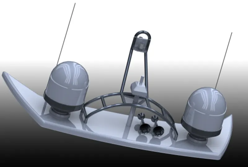
- Radar Mast
Tools/ Features:
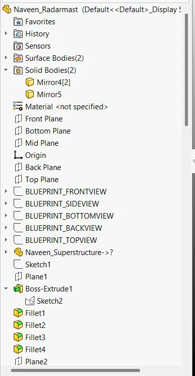
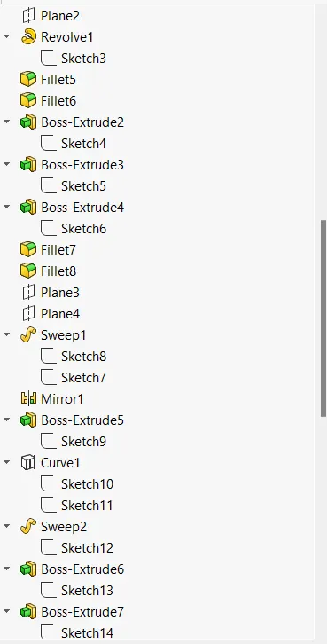
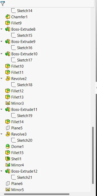
Tools and features used: Plane, Extruded Boss/Base, Fillet, Revolved Boss/Base, Swept Boss/Base, Mirror, Projected curve, Chamfer, Dome, Shell
Steps:
- Plane - A reference plane is added based on the selected reference either a plane, sketch or reference point.
- Extruded Boss - Extrude the sketch to desired length. Draw another sketch in Mid pane and Extrude.
- Fillet - It is used to smoothen the sharp edges to desired radius.
- Revolved Boss/Base - To create a solid feature, a sketch or it is selected contours are revolved with axis.
- Swept Boss/Base - Creates a surface by sweeping closed profile along a reference path.
- Mirror - Mirror the desired body, face or feature with reference to centre line, axis, face or plane.
- Projected Curve - Project the sketch from 2 different planes to form a single curve.
- Chamfer - Similar to fillet, this feature helps to create a bevel of desired distance on a intersecting edges.
- Dome - This creates a dome shape to selected face.
- Shell - Create a thin wall of desired thickness, from a solid body
Decals:
Add desired decals to the part using Photo 360.
Assembly:
- To complete the model, Each and every part need to be assembled.
- First import the Hull, followed by super structure.
- Add front and middle seat
- Rear seat needs to be added with mate. Use appropriate mate to fix the rear seat
- Add garage door with the appropriate mate.
- Added Radar mast and Use mates to attach Radar with mast.
- Finally add propellor to the propellor shaft with mates. Repeat the same to add remaining 2 propellors.
Rendering:
For Rendering we need to choose Perspective view and we need to add Camera.
Snaps of Rendered Assembly:
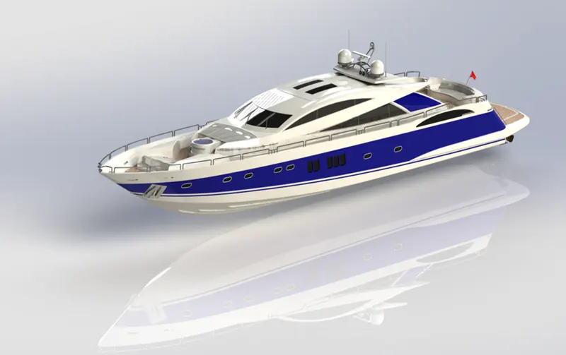
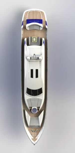
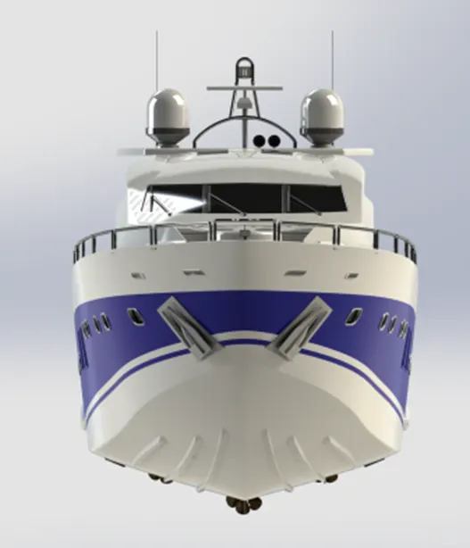
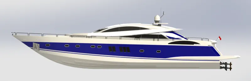
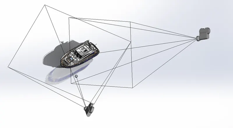
Photo Realistic Render: