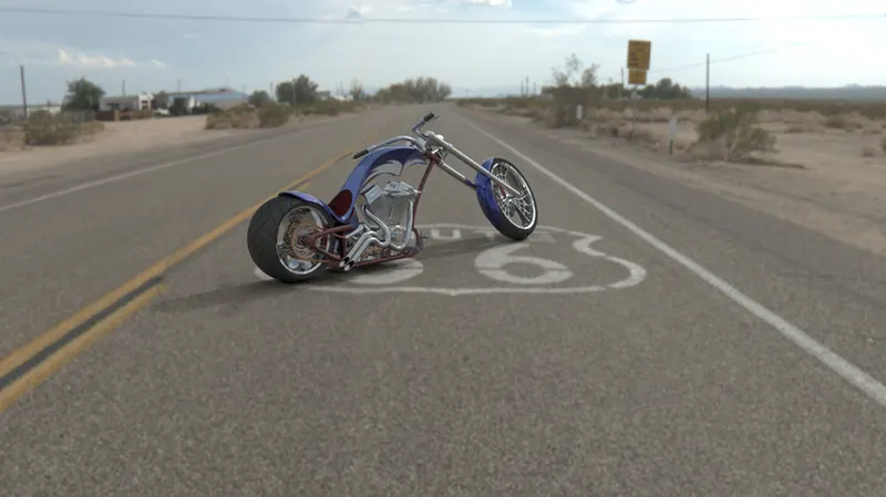
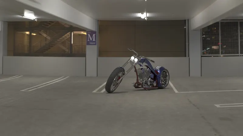
Photo Realistic Rendering
3D MODELING, ASSEMBLY AND RENDERING OF CHOPPER
- OBJECTIVE:
To create a American chopper model, Each component is modelled using Solidworks. It is then assembled and Rendered in Solidworks and Finally Photo Realistic Rendering is performed in Solidworks visualize. Understanding the tools and Features of Solidworks.
- INTRODUCTION:
In this project we will be learning skills sets required to Model American Chopper in Solidworks. We will be starting from scratch i.e from Sketch and till Photo Realistic Render.
- DESIGN METHODOLOGY/APPROACH:
We will developing the model in a part by part basis. Each part is designed individually from dimensionally constraint 2D sketches and then converted 3D bodies. The developed parts are assembled to create a complete model. Approach to modelling the chopper is as follows:
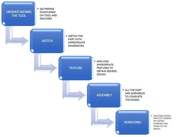
Components to be Modelled for Chopper:
- Transmission Belt
- Kick stand
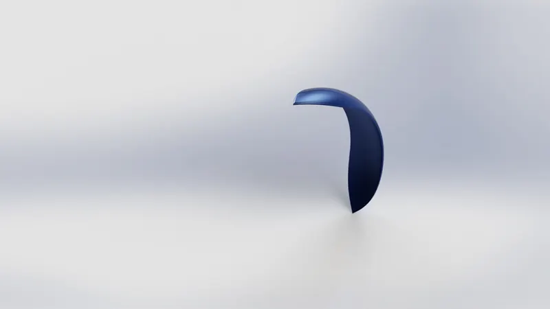
- Front fender
- Rear fender
- Chain
- Oil tank
- Pedal
- Front wheel/Rear wheel
- Front fork
- Chassis
- Engine
- Fuel Tank
- DESCRIPTION: Tools/ Features used to design the Part files.
First and foremost, step for all the 3D modelling in Solidworks is to create a template. It should be done before beginning the project.
In this stage required parameters are set such as the drawing units (Millimetre, gram, second or meter, kilogram, second). Rename reference plane, so that whenever new part is created, we use this template for reference.
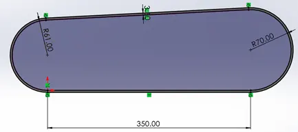
- Transmission Belt:
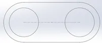
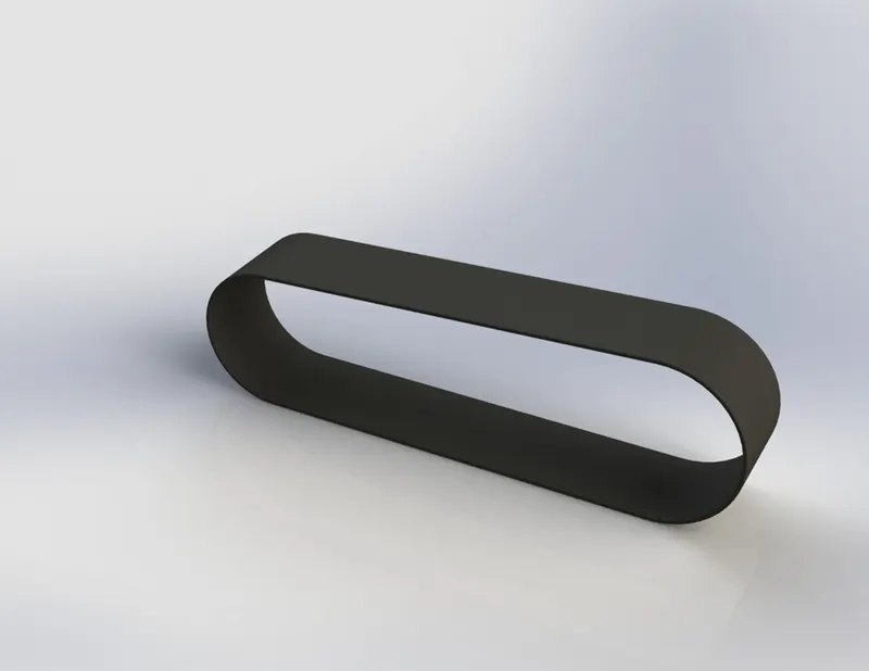
Transmission belt involves basic sketch to 3D model conversion.
First step is to select the template which we have created for the course. Then required Plane selection is identified and Renamed as per our requirement. It is will help us identify the plane for easy assembly.
Tools/ Features:
Tools and features used: Line, Offset, Dimension, Extruded Boss and Fillet.
Steps:
- Plane selection – Select the appropriate plane and rename as per the model (Front plane Transmission Belt, Top plane, Right plane Transmission Belt) and create sketch. It will switch to sketch editor
- Line - We start by selecting the line tool followed by Arc tool using tangent option.
- Offset – Created sketch is offset at certain to provide thickness for the belt to be create.
- Dimension – Once the sketch is completed, we need to apply dimensions to that sketch appears black meaning fully constraint. Make the bottom corner of the screen shows fully defined. Then exit the sketch editor
- Extruded Boss – This feature helps to derive 3D solids from a 2D sketch
- Fillet – Fillet option creates rounded edges to the corner.
- Appearance - Apply materials in the appearance tab, matching the part.
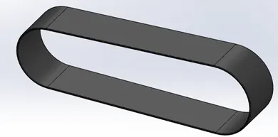
- Kick stand
Tools/ Features:
Tools and features used: Eclipse, Spline, Offset, Dimension, Extruded Boss, Extrude cut, Fillet, Dome and split.
Steps:
- Sketch - Start a sketch with Eclipses in a plane, create another one ellipse perpendicular to the first one and connect them both with a spline.
- Loft – Use loft to create a solid in the shape of both ellipse with spline as reference guideline.
- Dome – Use Dome feature to create rounded solid on both the elliptical surfaces.
- Cut Extrude – To remove a solid in a desired shape. We can create slot in a solid body using this comment.
- Fillet – Add Fillet to the edges.
- Appearance - Apply materials in the appearance tab, matching the part.
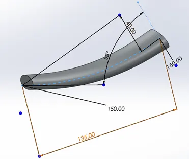
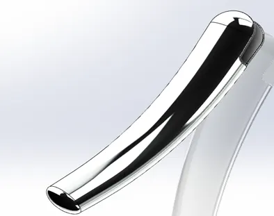
- Front Fender
Tools/ Features:
Tools and features used: Revolve, Split, Fillet
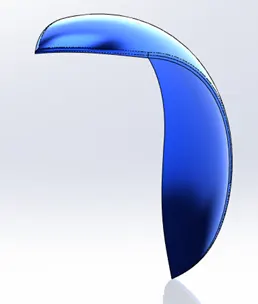
- Sketch – Rename the planes as Vertical plane – Front, Centre plane – Front, Mid plane – Front. Then start the sketch on vertical plane. Create 3-point arc, offset the arc to 6mm and join the edges of the arc.
- Revolve – Revolve the sketch about its axis to the desired angle, here we use 2 angles in direction 1 and 2 for the range.
- Split – Create another sketch in the shape of the part to be deleted. Use split feature to remove the part (Consume option will delete the split part completely).
- Fillet – Add Fillet to the edges.
- Appearance - Apply materials in the appearance tab, matching the part.
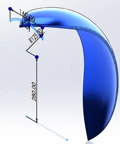
- Rear fender
Tools/ Features:
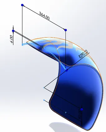
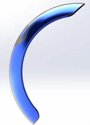
Tools and features used for Rear fender is identical to the front fender.
Steps for developing Rear fender is same as Front. The only difference is the revolve angle it is 5° and 130° for Front, 10° and 140° for the rear.
- Chain
Tools/ Features:
Tools and features used: Block, Trim, Fillet, Extruded Boss, Pattern, Mirror
Steps:
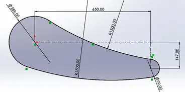
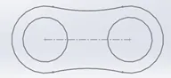
- Sketch – Select the desired plane and rename them as, Mid plane chain, Centre plain chain and Front plane chain.
- Block - First step is to create block for the chain link. Draw inner and outer chain links and save them as a block separately. Then create a path/shape of the chain link to be patterned.
- Extruded Boss – Insert the created blocks on the path of the chain and extrude the Chain link body and pins separately.
- Fillet – Apply Fillet to all the edges of the chain link
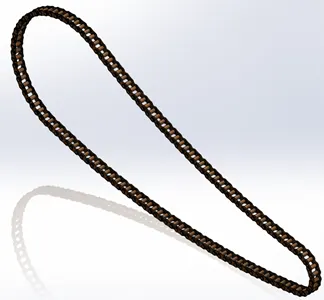
- Pattern – After extruding the link, Use Curve driven pattern to repeat the chain link links along the path. Repeat this step until entire path is interlocked with chain links.
- Mirror – Once pattern is complete, Mirror the pattern with respect to mid plane chain.
- Appearance - Apply materials in the appearance tab, matching the part.
- Oil Tank
Tools/ Features:
Tools and features used: Line, Spline, Circle, Extruded Boss, Combine, Shell and fillet
Steps:
- Sketch – Select the desired plane and rename them as, Mid plane – Oil tank. Create a sketch in top plane.
- Extruded Boss – Extrude the sketch to desired length. Draw another sketch in Mid pane and Extrude.
- Combine – Combine both solids by only keeping the common portion intact.
- Fillet - Apply Fillet to all the edges
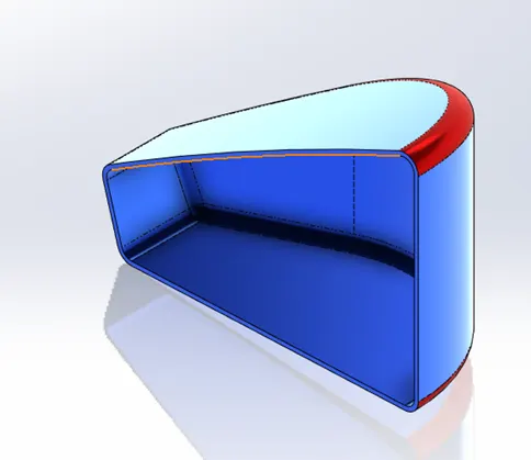
- Shell – This feature creates hollow body to solid to desired thickness.
- Appearance - Apply materials in the appearance tab, matching the part.
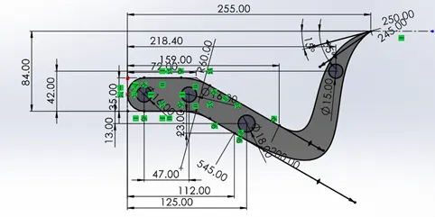
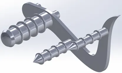
- Pedal
Tools/ Features:
Tools and features used: Arc, Spline, Circle, Extruded Boss, Fillet, Dome, Linear pattern and Chamfer.
Steps:
- Sketch – Draw a sketch of pedal with Arc, spline and line tool. Dimension them until it is fully defined.
- Extruded Boss – Extrude the main body and then extrude the hinges of the pedal.
- Revolve – Foot rest is derived using revolve feature. This feature helps revolve any 2D profile at desired angles.
- Dome – Create a dome at the flat side of the foot rest to get rounded solid.
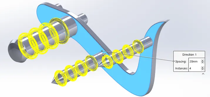
- Pattern – This feature helps to create repetition of the solid in an axis, either in “Linear pattern” or “Circular pattern”. We will be using Linear pattern option for the pedal
- Fillet – Fillet the internal and external faces.
- Appearance – Apply materials in the appearance tab, matching the part.
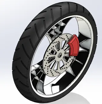
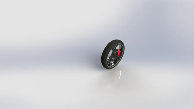
- Front Wheel/Rear Wheel
Tools/ Features:
Tools and features used: Line, arc, circle, rectangle, spline, Revolve, Revolve cut, Extruded Boss, Fillet, Pattern, Chamfer
Steps:
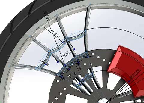
Sketch – This is a complex design we will drawing them separately. Rim, Spoke, Rotor, Calliper then Tyre.
Rim/Spoke:
- We can start with rim, sketch the cross-section shape of the rim on the front plane.
- Revolve the shape to 360 deg to form the rim.
- For spokes start the sketch on the Right plane. Sketch the outline block of the web shape and extrude.
- Draw the web shaped block on the extruded face. Use Extrude cut to delete the unwanted portions
- In Mid-plane draw a curvature to remove the excess portion of the spoke.
- Use Revolved Cut feature to cut the excess portion on the spoke.
- Then add Circular pattern feature to replicate the spoke. Then Combine to form a single solid object.
Rotor:
- To create Rotor, start a sketch on right plane with a circle and extrude.
- On the surface of the Rotor/Disk, draw circle to cut holes on the Rotor. Extrude cut the circles and Use Circular pattern feature to create copy of the Pattern.
- To create second pattern, start a sketch on the Rotor. Similar use Extrude cut and Circular pattern.
- For Axle hole, create a circle at appropriate diameter and Cut extrude.
- Provide fillet at the edges.
Calliper:
- In the front face of the Rotor, draw the sketch of the calliper and Extrude it.
- Provide chamfer for both the sides of the calliper and Add Fillet to the edges.
Tyre:
- Select front plane and draw a sketch resembling profile of the tyre.
- Use Revolve feature to get the Complete surface of the tyre.
- For grooves, sketch the profile to be cut extrude on the surface of the tyre.
- With Circular pattern, repeat the grooves of the tyre.
- Appearance - Apply materials in the appearance tab, matching the part.
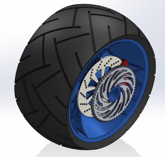
For Rear wheel repeat similar steps with different dimensions. The difference we need to design sprocket
Sprocket:
- Create a profile for the sprocket and Extrude using Extrude with offset option.
- For Gear tooth on the sprocket draw a profile on the face of the sprocket and cut extrude the shape.
- Then use circular pattern to replicate the tooth profile around the sprocket.
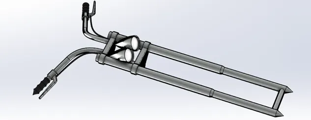
- Front Fork
Tools/ Features:
Tools and features used: Spline, Line, Circle, convert entities, Trim, Extruded Boss, Dome, extrude cut, Projected curve, Swept Boss, Combine, Mirror and Fillet
Steps:
- Create a sketch on the Front plane, draw the profile for the tubular fork. Use Revolve to obtain the Fork tube.
- For clamp assembly create a profile on the Right plane and extrude. Use linear pattern to create copy of the clamp.
- Create axle at the bottom of the fork, sketch a circle and Extrude.
- Sketch the Headlamp profile and use revolve feature to get headlamp assembly.
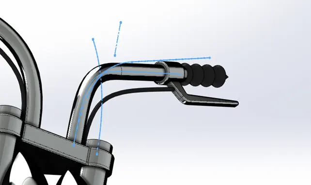
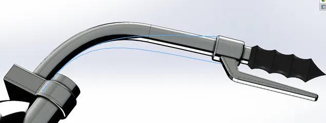
- For handle bar we will be using project curve feature. Create a sketch in both Right plane and Top plane using Spline. Then project those 2 lines to form a profile for handle bar. Create a circle at the end of the profile. Using Sweep feature with the projected curve as reference path, we can derive handle bar.
- Sketch the profile for grip of the handle bar and by using revolve feature.
- Sketch the profile for brake lever and extrude. Fillet the edges to desired radius.
- For brake cable, similar to handle bar. We will be using projected curves for the brake cable.
- Mirror entire assembly along the Front plane to complete the Front fork assembly.
- Appearance - Apply materials in the appearance tab, matching the part.
- Chassis
Tools/ Features:
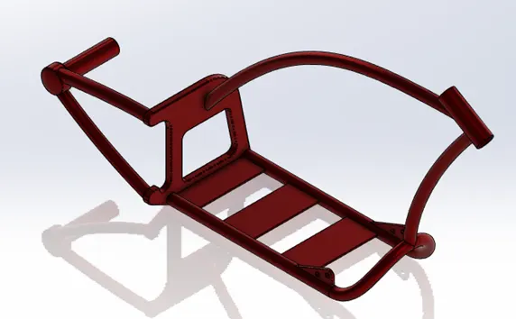
Tools and features used: 3-Point Arc, Line Spline, Circle, Extrude boss, Dome, Cut Extrude, Revolved cut, Project Curve, Swept Boss, Revolve, Combine Mirror, Chamfer and Fillet.
Steps:
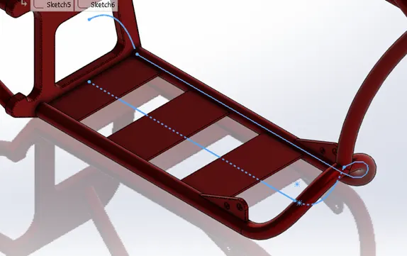
- Blue print: In this stage we will inserting Blue print to have an outline of the chassis.
- For the tubular structure we will be projected curve and Sweep feature to form the structure.
- Sketch the profile using spline on the Mid plane and bottom plane.
- Using projected curve of the both sketches and create a curve.
- Sketch another profile on the right plane and using projected curve.
- Create a circle on the mid-plane at the end of the projected curve. Using Sweep with curve as path complete the tubular structure.
- Mirror the tubing based on Mid plane chassis. Complete the bottom structure of the chassis.
- For the bulk head behind the chassis. Create a sketch on the right plane and extrude.
- Create a cut out on the Extruded face and Fillet the edges.
- For rear hub assembly of the chassis, create a Plane with reference to mid plane chassis.
- Create a profile on the new plane and a circle face of rear bulk head. Sweep the circle with reference to the profile.
- Follow similar procedure for the bottom profile.
- Create circle at the end of rear assembly and extrude the hub part of the chassis and Create another extrude for the axle.
- Use Dome feature on the flat end of the hub.
- For Top part of the chassis, create a profile on the mid plane and Circle at the edge of the profile.
- Sweep Circle with reference to the profile to obtain the top of the chassis. Using Split feature delete the unnecessary end of the tube.
- To connect the top and bottom of the chassis, draw a profile on Mid plane at the end of the profile, Create another plane. Add a circle at the newly created plane and sweep the circle.
- At the end of swept profile, create a sketch and revolve which connects the top 2 pipes.
- Using split delete unnecessary material from the chassis.
- Create a sketch for bottom plate and extrude.
- Create a sketch for Pedal hinges and extrude. Mirror the solid with reference to Mid plane.
- Finally create a sketch for side stand holder and extrude. Provide a hole using cut extrude.
- Fillet – Fillet the internal and external faces.
- Appearance - Apply materials in the appearance tab, matching the part.
- Engine
Tools/ Features:
Tools and features used: Line, 3 Point arc, Spline, Circle, Convert Entities, Offset entities, Extrude Boss, Extrude cut, Revolved Cut, Projected curve, Composite curve, Swept Boss, Revolve, Combine, Mirror, Fillet
Steps:
- Insert Blueprint of the chopper and set it to desired Transparency.
- Create a sketch on the Front plane to form the bottom portion on the Engine. Extrude the profile
- Create another sketch and extrude to from rear portion of the engine. Fillet the edges to smoothen the edges.
- We can draft the transmission shaft for the belt drives. In the rear face of the create a sketch and draw the profile of the transmission shaft.
- Revolve the profile to form the first shaft. Follow the same procedure to create the rear transmission shaft.
- To form the groove for the shaft. Sketch a profile of the groove and use cut extrude the profile.
- Create a Circular pattern of the profile to get grooves for the shaft. Follow same procedure to form groove rear transmission shaft.
- Create Dome of both faces of the transmission shaft. Cut holes on the dome surface, with cut extrude Feature.
- Fillet and Chamfer the edges of the transmission shaft wherever necessary.
- For the starter, Draw the profile on the Front plane and Extrude. Smoothen the edges with Fillet feature.
- Now we can create a new plane for the cylinder head and body.
- Create a base profile for the cylinder body and Create a plane at the end of the profile.
- Create 3 sketches on the new plane and extrude to form, Cylinder head, cylinder.
- Provide chamfer and Fillet of the cylinder head and body.
- To provide cooling fins for the cylinder. Cut extrude a profile and use Linear pattern to replicate the shape.
- Sketch the spark plug profile and Extrude. Fillet the edges to smoothen the solid.
- Now using Split feature split the Cylinder body and bottom portion of the Engine.
- Mirror the cylinder with reference to Right plane and Create the V twin Engine.
- Create the bottom mount for the engine. Create a profile and extrude.
- For Air intake manifold, create a profile and sweep between two cylinders. And create another profile between the first and sweep outside.
- Sketch the inlet filter for Intake manifold and Revolve. Cut extrude for Filter design and Create Circular pattern to complete the shape.
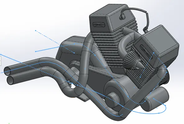
- We will be creating dual exhaust for the engine model.
- Create a sketch on the Right and Bottom plane using Spline and Project the curve.
- Create another profile and project the curve.
- Combine both projected curves with Composite curve feature.
- Draw a circle at the end of the profile and sweep to form first exhaust. Repeat the same steps to obtain the second exhaust.
- On the edge of spark plug, create a profile to sweep the Spark plug cables. Repeat the same for another spark plug.
- Appearance - Apply materials in the appearance tab, matching the part.
- Fuel Tank
Tools/ Features:
Tools and features used: Spline, Convert entities, Offset, Project curve, Surface sweep, Mirror, Combine, Knit surface, Swept Cut, Shell and Fillet.
Steps:
- Insert blueprint of the Chopper model and Set desired Transparency.
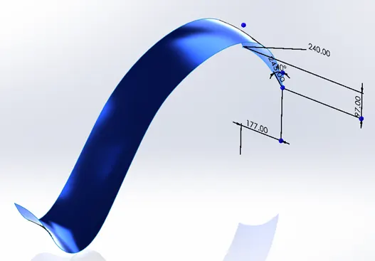
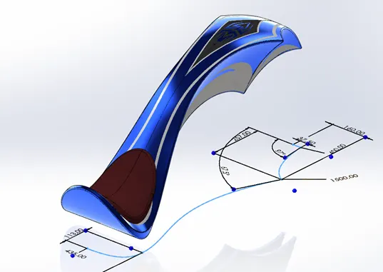
- To form top surface of the Fuel tank, create a sketch on Middle plane and front plane, use surface sweep feature to get Top surface of the tank.
- To obtain the desired shape of tank. Create a profile on the bottom plane and use Surface trim to cut the unnecessary surface.
- To create side profile of the tank. We will be using projected curve option to obtain side panel of the tank.
- Sketch the profile for front portion of the tank and project the curve.
- Use Surface loft feature to fill the surface.
- For rear end of the fuel tank. Sketch a profile and use Boundary surface feature to fill the rear panel of the fuel tank.
- Mirror entire body of the tank with reference to Mid plane, to complete the tank model.
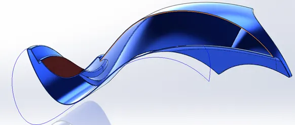
- For combining surfaces, we will be using Surface knit feature.
- For seat, create a desired sketch for the seat profile. Use Split line to split line on the surface of the tank. Then surface extrude the seat and fillet the edges.
- Surface loft to fill the bottom of the gas tank. Surface knit to combine all the surfaces.
- Fillet all the necessary edges.
- For the tank to be placed on the chassis, create a profile and cut sweep the profile, to cut away the gap.
- Finally use shell feature to finish of the tank.
- Appearance - Apply materials in the appearance tab, matching the part.
Decals:
Add desired decals to the part using Photo 360.
Assembly:
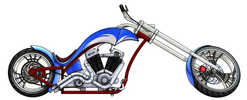
- To complete the Chopper, it should be assembled to form a single model. Each and every part is combined using Mates options.
- There are different types of mates, Coincident, Parallel, Perpendicular, Tangent, Concentric, Lock, Cam, Slot, Hinge, Gear, Rack Pinion, Screw, Joint, Width, Path, Linear.
- We will be using Coincident, Distance, Concentric, Parallel and Tangent.
- Open the assembly template, Since Chassis is the integral part of any vehicle. We will first add chassis.
- Followed by we will be adding engine, now engine is mated with the chassis using Coincident Mates.
- Then add pedal using Concentric and coincident mate to the respective hole.
- Use mirror pedal option to replicate the pedal, along with mates.
- Join Kick stand to the chassis with concentric mates. Since kick stand is movable at certain angle So we can set angle mate of the
- Add Transmission Belt and mate based on the Engine with Angle and width mate.
- Add oil tank with coincident mate on the engine.
- Mate rear wheel with the axle, to fix rotation parallel mate with Right plane chassis.
- Similarly add Rear wheel and mate based on rear wheel and chassis.
- Parallel mate the chain with chassis.
- Add fuel tank and mate based on Chassis.
- Mate front fork with the Chassis. Just like kick stand set the Front fork with position mate.
- Mate front wheel to front axle of the chassis using Coincident mate. Similarly, mate front fender.
- To position the entire model. Mate the wheel and Kick stand to the Top plane.
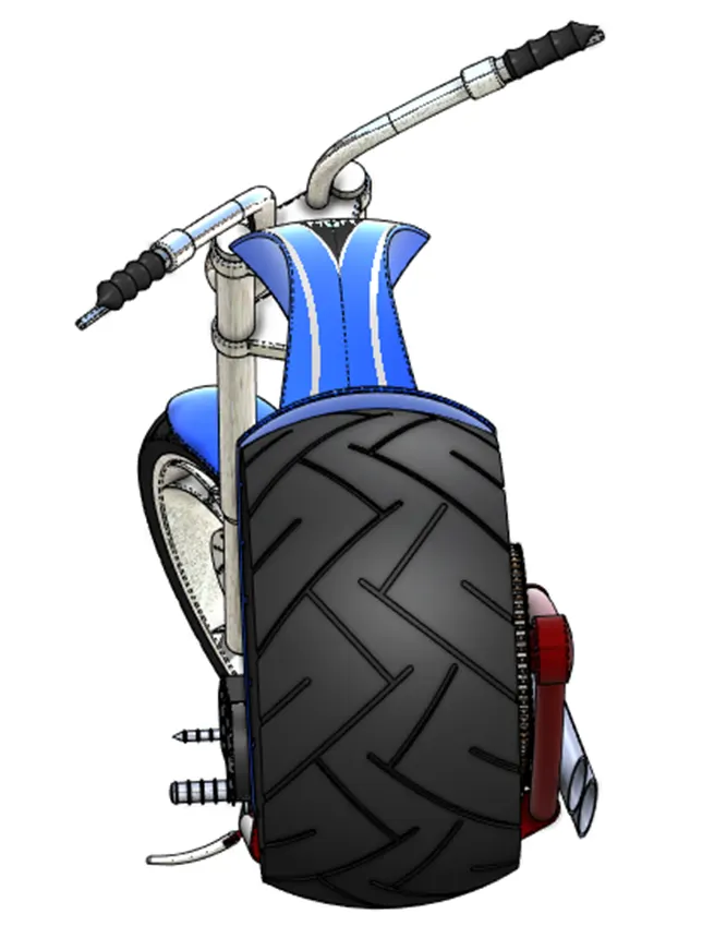
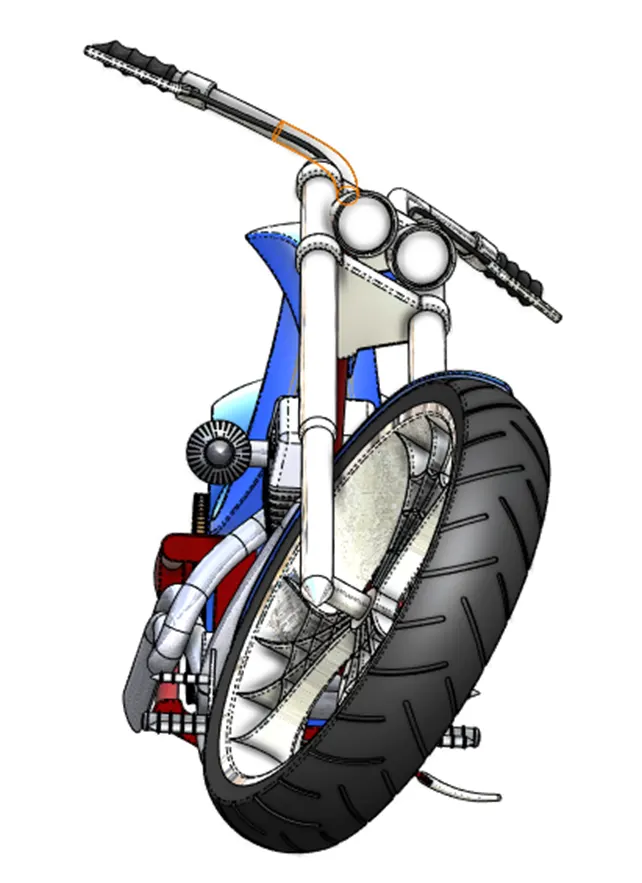
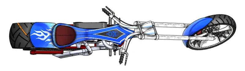
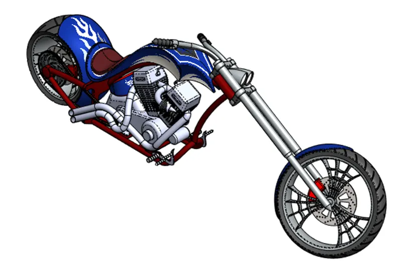
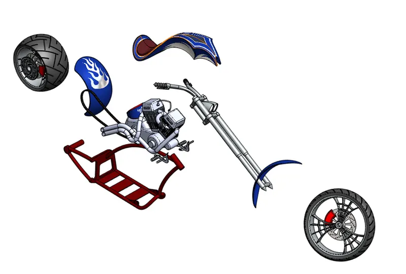
Snaps of Assembly:
Rendering:
For Rendering we need to choose Perspective view and we need to add Camera.
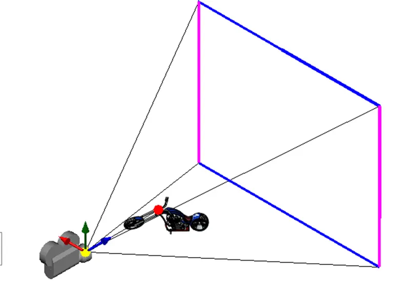
Rendering Snaps:
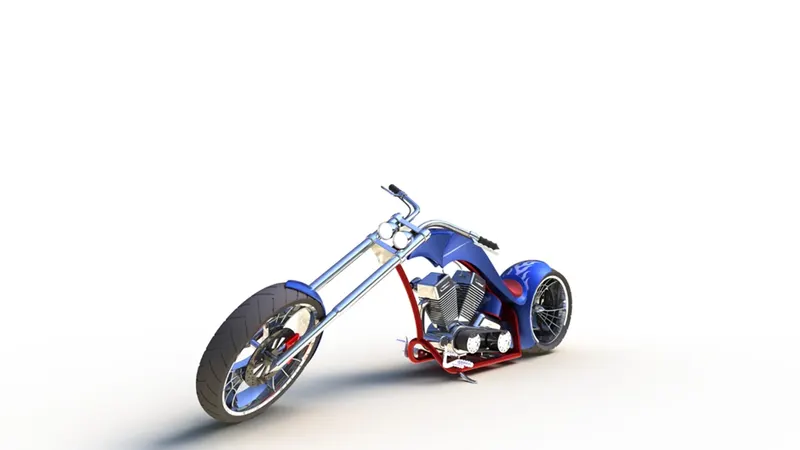
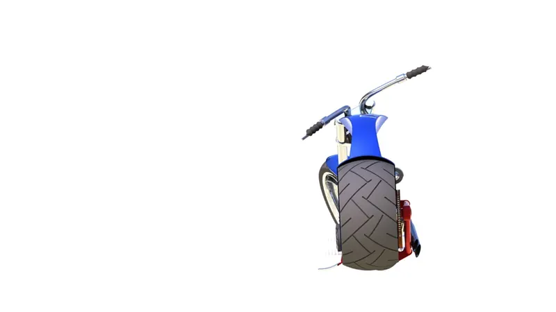
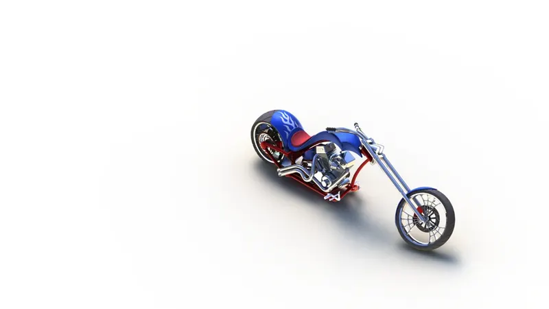
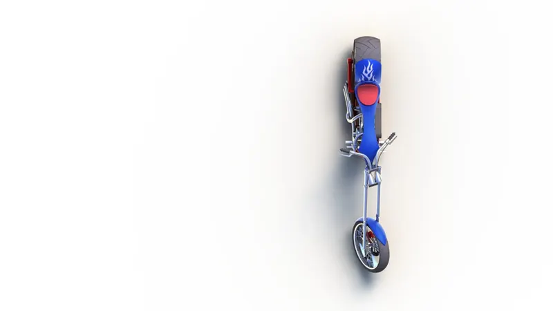
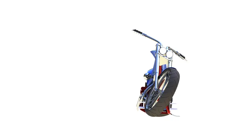
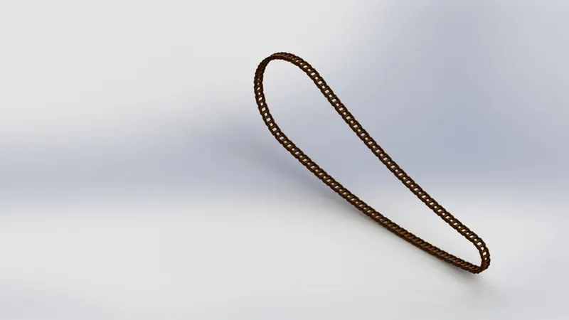
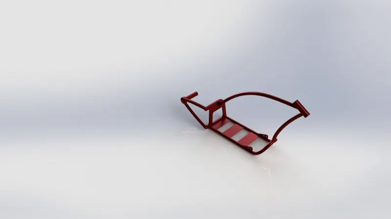
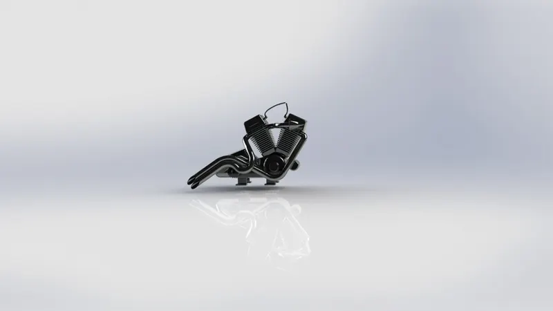
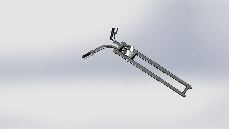
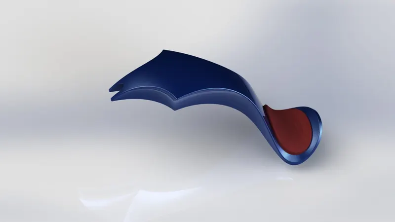
*Decals for rendering looks upside down for Fuel tank. But I have manually them to Photo realistic render.
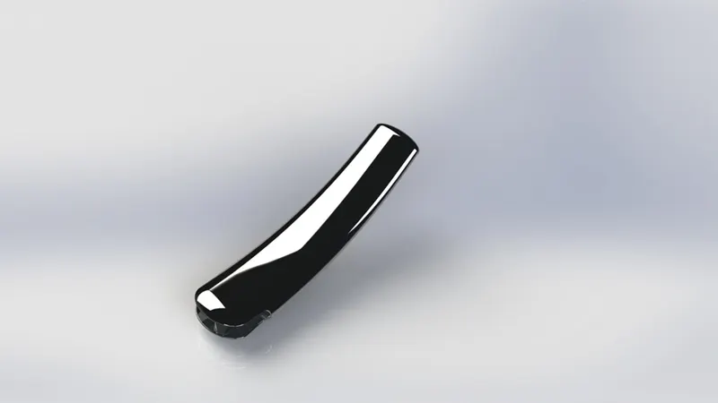
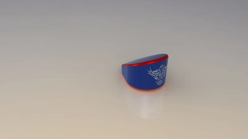
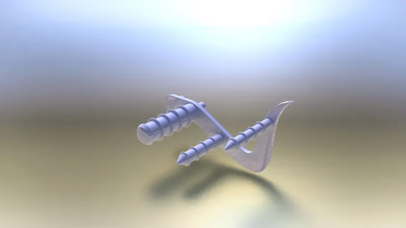
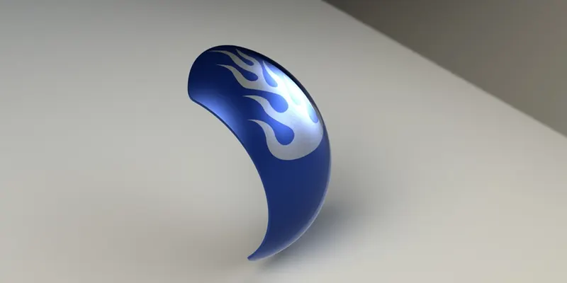
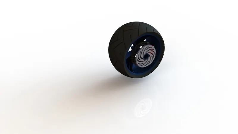
Photo Realistic Render: