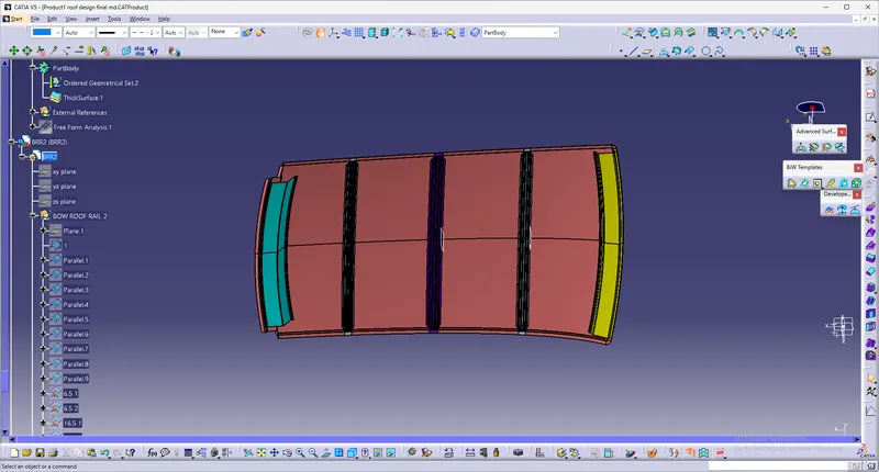
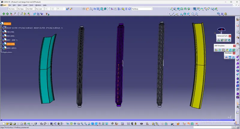
Roof Design
INTENT :
For the Given Roof styling, create an ASSEMBLY by developing the essential flanges for the outer roof and creating the reinforcements. Provide appropriate dimensions and check for Draft analysis.
AIM: For the given car roof styling, design and develop the essential flanges and reinforcement, namely the Ditch area, Frontal Roof rail, Rear roof rail, Centre Roof rail, and Bow roofs.
Suggest and implement remedies in the design if the criterion is not full-filling
Start with the creation of a roof ditch area with a tool opening angle of 7 degrees.
Develop the reinforcements as separate parts
Bow–Roof Prediction Formula
W = [1.73 x 10^(-3) x L] + [1.85 x 10^(-8) x (R^2)/t] + [ 1.10x10^(-3) x l] - 2.68
Where,
L = Roof Length in X-Direction[mm](Roof dimension in 0-Y)
R = Roof curvature
R = 2(Rx*Ry)/(Rx+Ry)
Rx = X curvature
Ry = Y curvature
t = Roof plate thickness [mm]
l = Bow Roof Span [mm]
Judgment Condition
OK< 2.7
Snow Load Prediction Formula
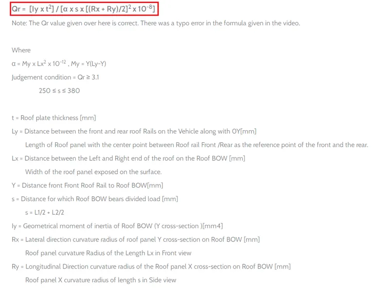
Qr = [Iy x t2] / [α x s x [(Rx + Ry)/2]2 x 10-8]
Note: The Qr value given over here is correct. There was a typo error in the formula given in the video.
Where,
α = My x Lx2 x 10-12 , My = Y(Ly-Y)
t = Roof plate thickness [mm]
Ly = Distance between the front and rear roof Rails on the Vehicle along with 0Y[mm]
Length of Roof panel with the center point between Roof rail Front /Rear as the front and rear reference point.
Lx = Distance between the Left and Right end of the roof on the Roof BOW [mm]
The width of the roof panel is exposed on the surface.
Y = Distance front Front Roof Rail to Roof BOW[mm]
s = Distance for which Roof BOW bears divided load [mm]
s = L1/2 + L2/2
Iy = Geometrical moment of inertia of Roof BOW (Y cross-section )[mm4]
Rx = Lateral direction curvature radius of roof panel Y cross-section on Roof BOW [mm]
Roof panel curvature Radius of the Length Lx in Front view
Ry = Longitudinal Direction curvature radius of the Roof panel X cross-section on Roof BOW [mm]
Roof panel X curvature radius of length s in Side view
Judgment condition
Qr ≥ 3.1
250 ≤ s ≤ 380
Here are some Reference images for the Master sections - These images are just to give you a brief idea about the design.
Front Roof Rail Master section
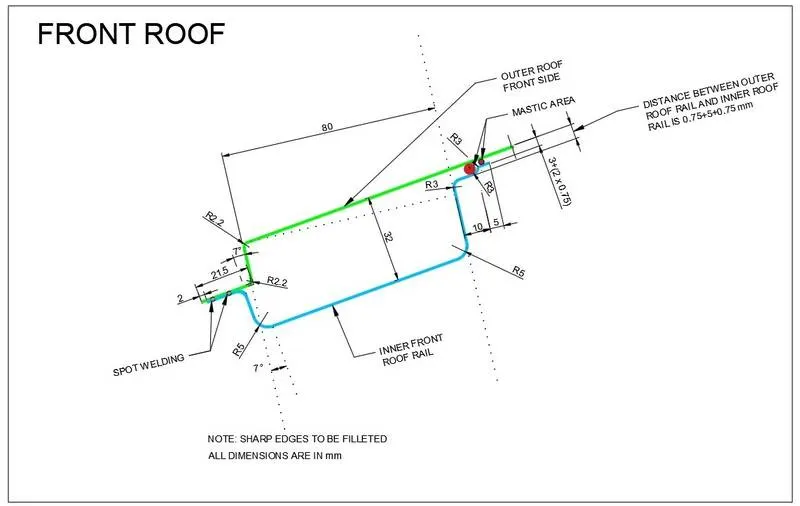
The master section of the Rear Roof Rail
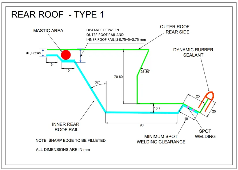
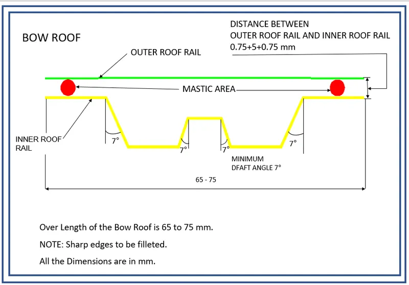
The master section of Bow Roof
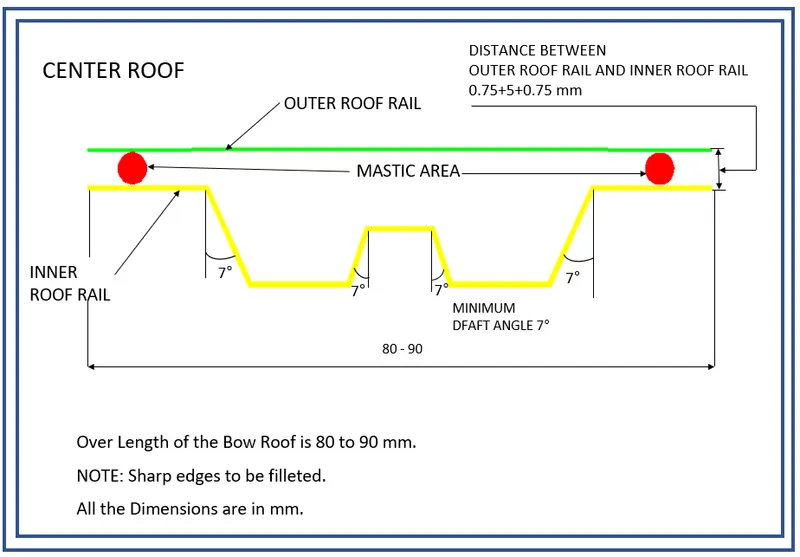
The master section of Center Reinforcement Rail
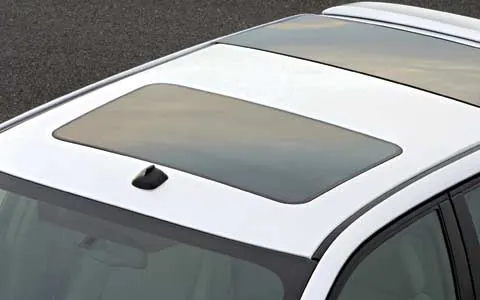
WHAT IS A ROOF IN AUTOMOBILES?
An automobile roof or car top is the portion of an automobile that sits above the passenger compartment, protecting the vehicle occupants from sun, wind, rain, and other external elements.
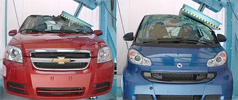
ROOF CRUSH TEST :
is the failure and displacement of an automobile into the passenger compartment during a rollover accident Every year approximately 10,000 Americans are killed in rollover accidents, accounting for about 30% of all light vehicle occupant fatalities.
The number of occupant injuries is significantly higher. The relationship between injury levels and intrusion or roof crush has been statistically established but the mechanism has been thought sometimes to be somewhat obscure. Theories advocating the idea that rollover injuries are caused by the occupants "falling" or "diving" into the vehicle interior have been advance
The roof crush test is the design given by the IIHS ( insurance institute of highway safety ). After analyzing the many accidents IIHS has then fixed some regulations, that how to perform the crush test
IIHS gives the rating based on this test. For this, they consider two points while giving the rating
- How fast the car can reform to its original shape after the rollover and
- How deep is the protrusion after the rollover
GOAL OF ROOF CRUSH TEST :
To minimize the protrusion into the occupant compartment, so that the seat belts and airbags can do their job in protecting the occupant
CONDITIONS TO FOLLOW FOR ROOF CRUSH TEST :
There are two conditions that should be followed for the roof crush test, they are
INITIAL CONDITION :
- Close and lock all the doors
- Close all the windows
SECOND CONDITION :
Fix the body sill or chassis frame on a hard lever surface horizontally
METHOD OF APPLYING THE FORCE :
The load is applied in such a way that 50 is tilted from the front end to the rear end and the load will be in 1800 mm in length and 750 mm in width. The load is applied at the position of 250 from the flatness of the roof. The load is applied on the roof for almost 120 sec and the crushing speed at which the load is applied is 13 mm/sec or less than that
RESULT:--
If the displacements go above the requirements level then we have to increase the bow roof thickness or add more mastics points to increase the strength. the stronger the roof the better it can protect the occupants in rollover crashes.
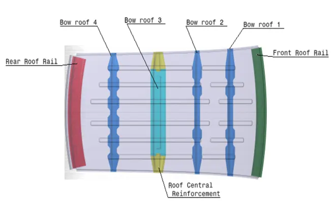
Now let's see what are all the parts are there on the roof:--
- OUTER ROOF
- FRONT ROOF RAIL
- BOW ROOF 1
- CENTER ROOF
- BOW ROOF 2
- REAR ROOF RAIL
Design Procedure:
Import the file. File>open>browse the file and select the given product(product name .igs) as shown in the figure below
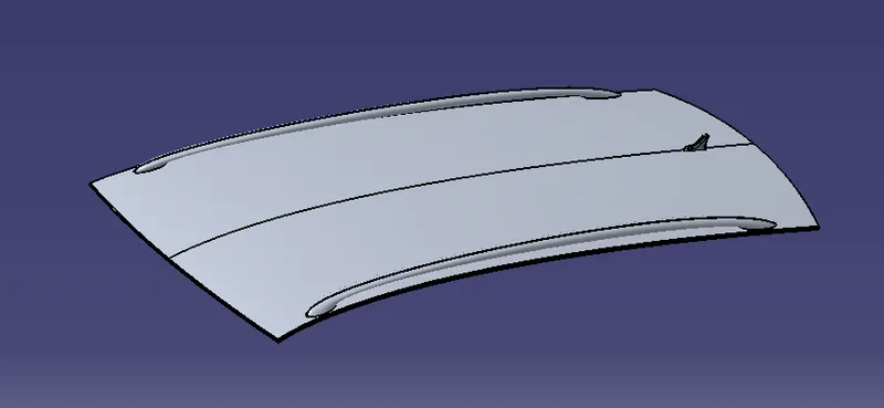
Roof Design
Given surface is A-class and we have to design the Roof surface with the help of this A-class and the help of master section which is shown below:There is two master section for the front-end Rail roof and the next one is for the rear rail roof section
Reinforcements and Design
The Ditch Area is the extended portion of the main Roof concealed by other BIW panels. The rail supports of the roof are attached to the Ditch Area using Spot welds. since it is not a styling surface and remains concealed
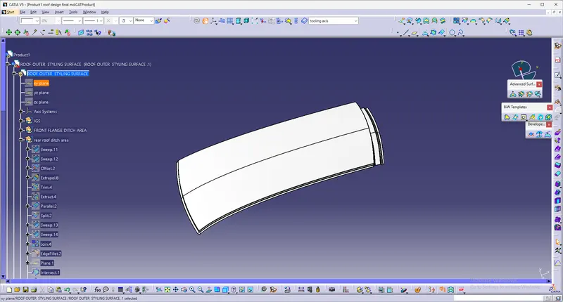
Front Roof Rail
It is the support that is joined by the windshield glass. Body side outer and inner panels. Its thickness is usually 0.75mm. The windshield end flanges are the extract offset of the roof surface. The bottom-most flanges are decided after taking into consideration the visibility criteria. Spot weld is applied at the windshield end of the other end is joined with the roof using Mastics sealants which also contributes to increased strength
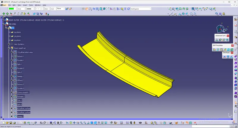
Rear roof rail
It is the support that is joined to the back door and the Body side outer and inner panels. it is usually made from body side outer scrap and therefore the thickness of the rail is 0.75mm. Similar to the Front roof rail design. We have to take into consideration the rear headroom clearance and the rear visibility criteria while designing the rear roof rail from the backdoor design and also take into consideration od the required clearance. Spot welds are applied at the back door end of the rail and the other end is joined with the roof using Mastic sealants.
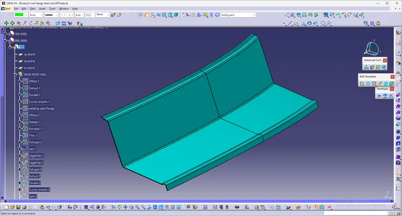
Bow Roof Rails
Similar to the other design, we have to take into consideration of the headroom clearance and the visibility criteria while designing the center roof rail and bow roof rail. Here spot weld is not applied for joining these rails of the roofs. Instead, mastic sealants are used are introduced at both ends since center Roofs are fully positioned under the styling surface of the roof. For increasing the strength of the rails, Embossing is done. To reduce the weight of the material used, different styling has been followed with a thickness of 0.75mm
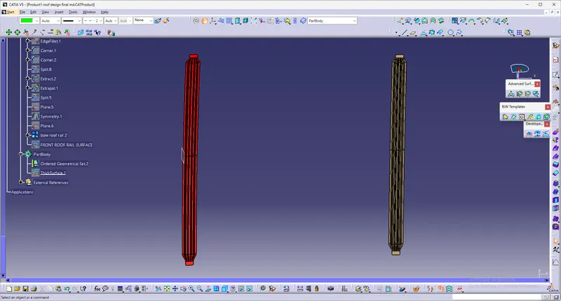
Reinforcement center rail
It is the main supporting rod for the roof. Their purpose is to provide an attachment point for crossbars and other devices designed to secure loads carried on the roof of the vehicle, it absorbs energy at the time of the crash. Its thickness is 1mm.
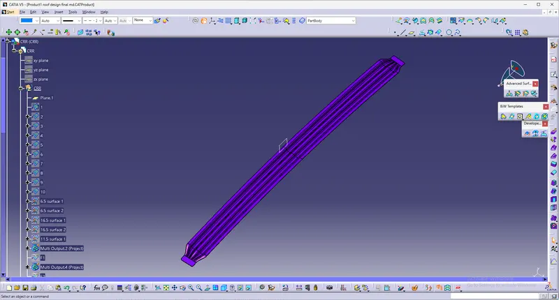
Analysis
1. CURVATURE STUDY:
It is done to justify the positioning of the bow roofs. There are mainly two criteria to fulfil
- Heat distortion criteria
- Snow load criteria
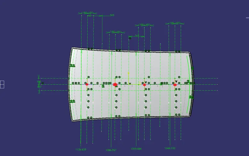
From the model, we have the value shown in fig
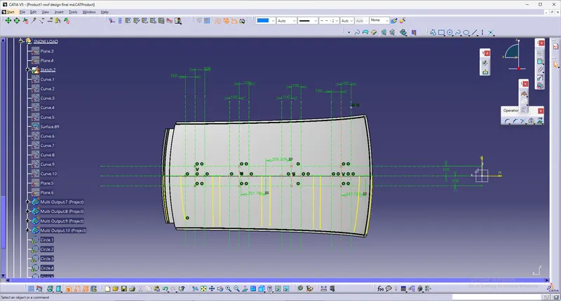
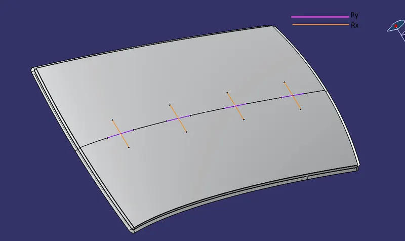
So after intersecting points on the line, we create 4 points and project them on the roof surface then join these points by using the spline option.
The horizontal line is Rx and the vertical line is our Ry the radius of curvature for the hood component along the x-axis is given below
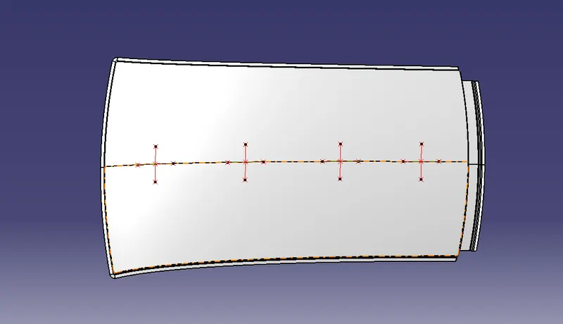
The radius of curvature for the hood component along the x-axis is given below
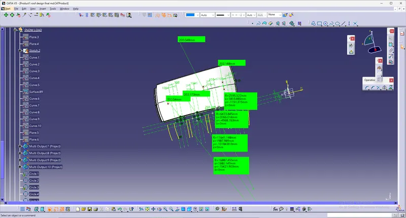
The radius of curvature of the hood component along the Y-axis is below
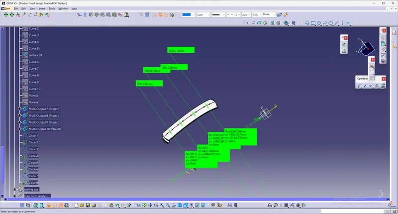
Snow Load Criteria:
After creating all the lines we intersect points and project these points on the hood by using the spline curve option this will look like given below figure:
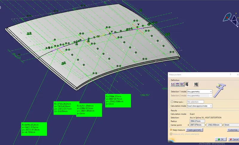
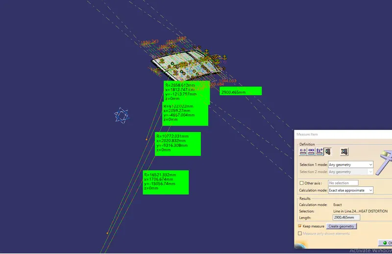
Calculations are done and tabulated in the table as shown below:

Draft Analysis:
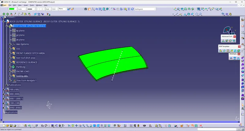
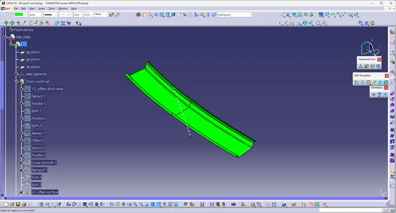
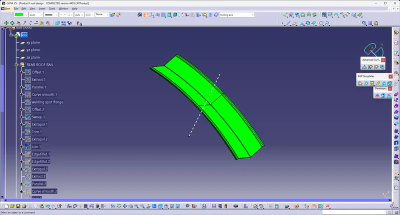
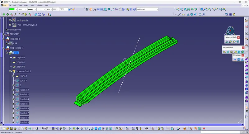
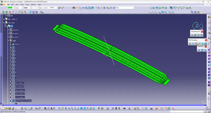
Draft analysis is a method of checking the draft angle on various faces of a part in a particular direction. it should be more than 7 degrees. draft analyzing command which lets you know if your model or design has a draft angle in a given tool direction.
If the part lies within the conditions it shows in green color if not shown in blue or red color.
The below figures show the draft analysis for the Roof, Front Roof Rail, Rear Roof Rail, Bow Roofs, and Reinforcement Cente
Results:
The Design of Roof, Front roof rail, Rear Roof Rail, Bow Roofs, and reinforcement roof center by following the Master section with the design parameter for the given class A surface is done and the final model is shown in the fig. below