Roof Design
PROJECT 3
ROOF DESIGN
AIM: To design car ROOF with essential flanges and reinforcements like ditch area, front ROOF RAIL, BOW ROOFS, CENTRAL ROOF RAIL and REAR ROOF RAIL for the given styling surface and Perform a curvature study on the roof and perform the calculation
CAR ROOF:
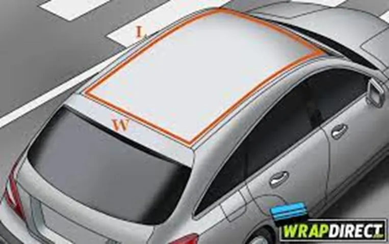
- An automobile roofor car top is the portion of an automobile that sits above the passenger compartment, protecting the vehicle occupants from sun, wind, rain, and other external elements. Because the earliest automobiles were designed in an era of horse-drawn carriages, early automobile roofs used similar materials and designs.
- Rollover crashes, especially in the country, are usually very destructive events. Vehicle damage often includes deformation of the roof and its supporting structures. Head and neck injuries are common, and associated with roof deformation. Strengthening of the roof is suggested as an appropriate countermeasure for such injuries.
- Design the roof with roof rails from the given styling surface with the master sections.
DESIGNING SOFTWARE:
- NX CAD
DESIGN CONSIDERATIONS:
- Front visibility criteria: for the clarity vision to see the all front portion on the road to the driver when in driving condition.
- Rear visibility criteria: in this when see the rear side from the mirror, design the rear side top with clear vision.
- Head room criteria: design the roof top to reduce the head injuries when crushing the roof with some force.
Reinforcements to the car roof:
- FRONT ROOF RAIL
- BOW ROOF RAIL 1
- CENTRAL ROOF RAIL
- BOW ROOF RAIL 2
- REAR ROOF RAIL
DRAFT ANALYSIS:
- The draft analysis technique is used to analyse whether our part model created in CAD is manufacturable based on the draft condition applied.
JOINING METHODS:
- Mastic points
- Spot welding
These methods were introduced to join the components, the mastic points is used for good looking purpose and its avoid the damage of the components. Where the spot welding is used for permanent attachment of the components.
TESTING METHOD:
Roof crush test:
- Roof crush test is the design given by the IIHS (insurance institute of highway safety). After analysing the many accidents IIHS has then fixed some regulations, that how to perform the crush test.
- IIHS gives the rating based up on this test. For this they consider two points while giving the rating
- How fast the car can regains to its original shape after the roll over
- How deep is the protrusion after the roll over.
- The main aim of the roof crush test is to minimize the severe injuries using the safety things like seat belts, air bags.
Conditions for roof test:
- Initial condition:
- Close and lock all the doors
- Close all windows of the cars
- Fix the body sill or chassis frame on a hard lever surface horizontally
Testing procedure:
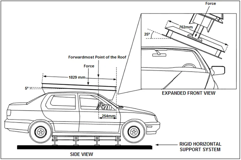
- The load is applied in such a way that 5 deg is tilted from the front end to the rear end and the load will be in 1829 mm in length and 762 mm in width.
- The load is applied at the position of 25 deg from the flatness of the roof. The load is applied on the roof for almost 120 sec and the crush speed at which the load applied is 13 mm/sec or less than that.
TOP ROOF:
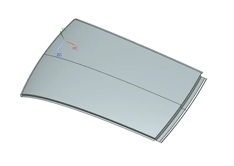
- Create a roof without touching the styling surface.
- It is symmetry to the plane so trim the half portion and work on it and then mirror it.
- Extract the top surface of the styling component and start to design.
- With given master section create a front side roof and rear side roof.
- This surface having a curvature because to increase the strength of the component.
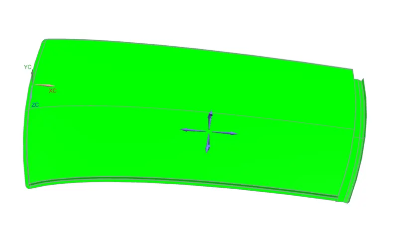
- Draft analysis for the roof component.
FRONT ROOF RAIL:
MASTER SECTION:
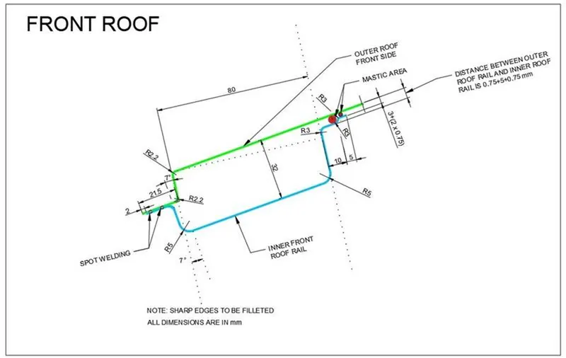
- Front roof rail is used to attaching the wind shield glass and the body outer side component.
- From the master section extract the roof top surface and offset it at a required distances.
- Check the direction is proper and create a law extension at required side with some given angle.
- Join all the surfaces and give the edge blends.
- For increase the strength create a embosses for this surface, if required.
- Thicken the component at 0.75 mm in the upward direction.
- Check the draft analysis for the final component.
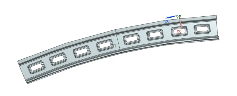
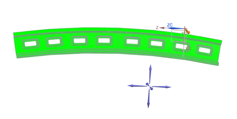
BOW ROOF RAIL:
MASTER SECTION:
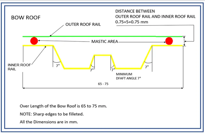
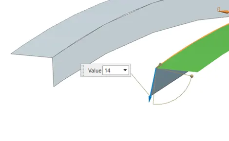
- Bow roof rail is one of the reinforcement and for the roof component two bow roof rails are attached.
- For the design of bow roof rail we need to create a datum plane on the roof curve at the 25%-35%.
- When the roof at front side is in curve shape, we don’t create any reinforcement there because its already have a strength on that place.
- For creation of bow roof rails we need to follow the master section.
- Create a two roof rails, first at near of the front roof rail and for another is placed in between the central roof rail and rear roof rail
- At finally do the draft analysis.
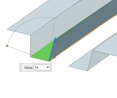
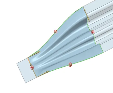
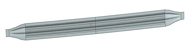
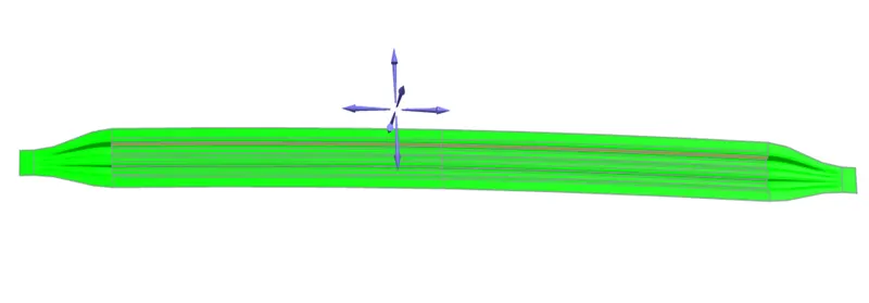
Bow roof rail 1:
Bow roof rail 2:
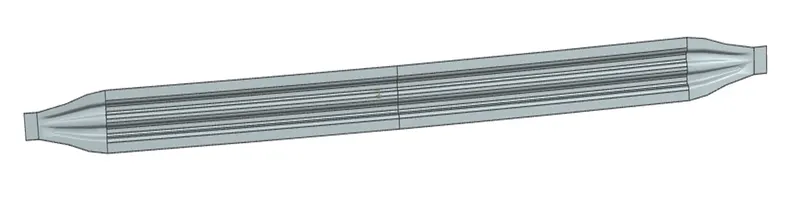
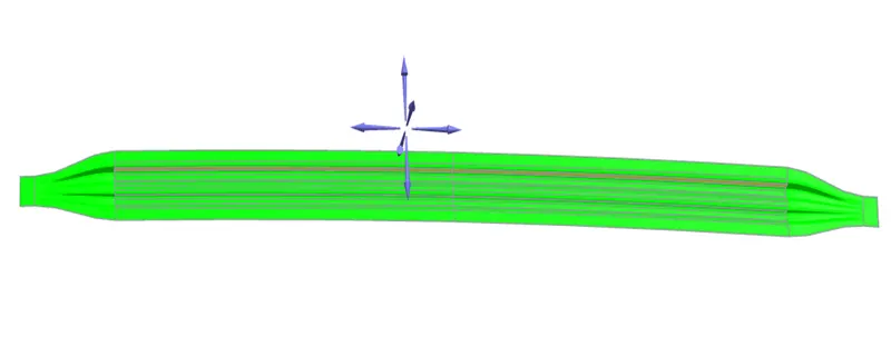
- This is the second bow roof rail.
CENTER ROOF RAIL:
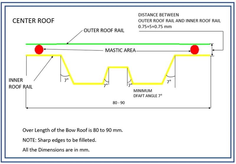
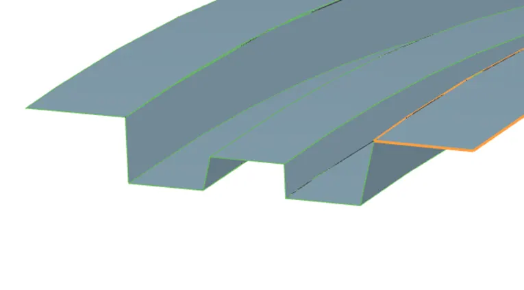
- It helps to provide the effective support to the flat surface and increase its strength when the load is applied on the top roof panel.
- This is same as the Bow roof rail but the difference is only in the width.
- The width of the bow roof rail is in between 80-90mm.
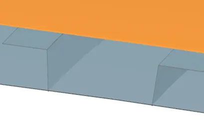
- Make sure that the offset of roof top to the bottom surface is not more than 20 mm and make design based on this. It cause head room criteria.
REAR ROOF RAIL:
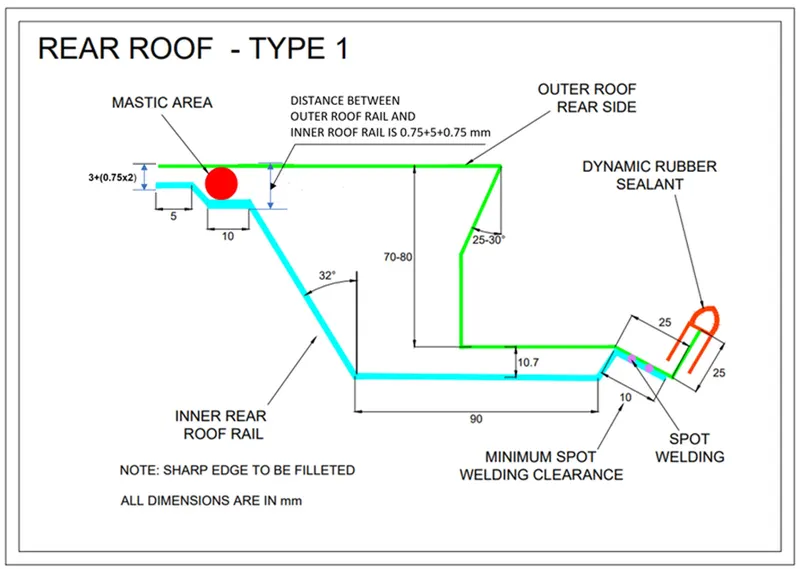
- Rear roof rail is the one which joins the back door of the panel and body side outer.
- It is designed based on the back door panel because, when the back door is in open condition it don’t touch each other.
- In this design the roof rail is based on the given master section.
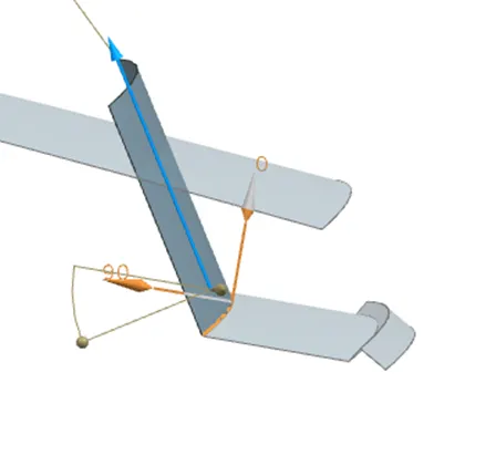
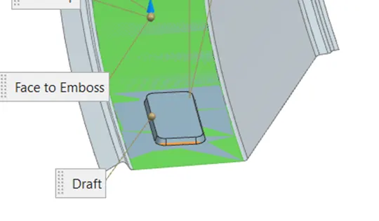
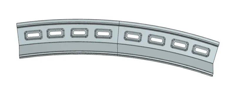
- Create an emboss for increasing the strength of the roof rail.
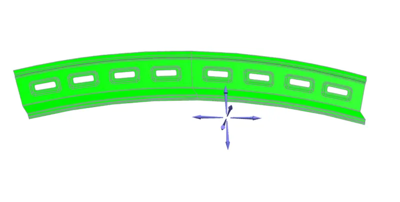
FINAL COMPONENT:
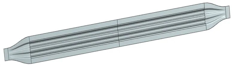
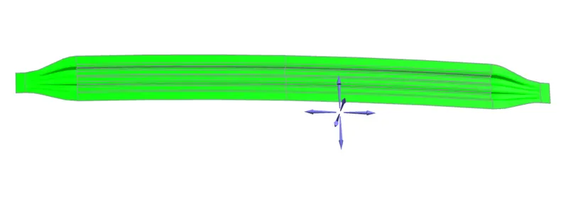
- Assemble all the parts and create a full roof component.
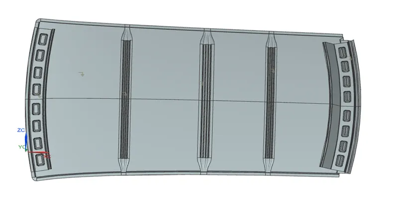
HEAT DISTORTION:
- some countries have above the temperature limit. For with stand this temperature we can analyse the component this fit for this or not.
- This have a limit range, it means less than 2.7
- This study is used to predict the heat distortion temperature at where the materialstarts to soften when exposed to a fixed load at elevated temperature.
- In order to avoid bending or damages on the roof, based on the heat distortion temperature, this study will predict the bow roof position which helps to strengthen the roof.
BOW – ROOF PREDICTION FORMULA:
- W = [1.73 x 10^(-3) x L] + [1.85 x 10^(-8) x (R^2)/t] + [ 1.10x10^(-3) x l] - 2.68
Where,
L = Roof Length in X-Direction[mm] (Roof dimension in 0-Y)
R = Roof curvature
R = 2(Rx*Ry)/(Rx+Ry)
Rx = X curvature
Ry = Y curvature
t = plate thickness [mm]
l = Bow Roof Span [mm]
JUDGEMENT CONDITION:
OK < 2.7
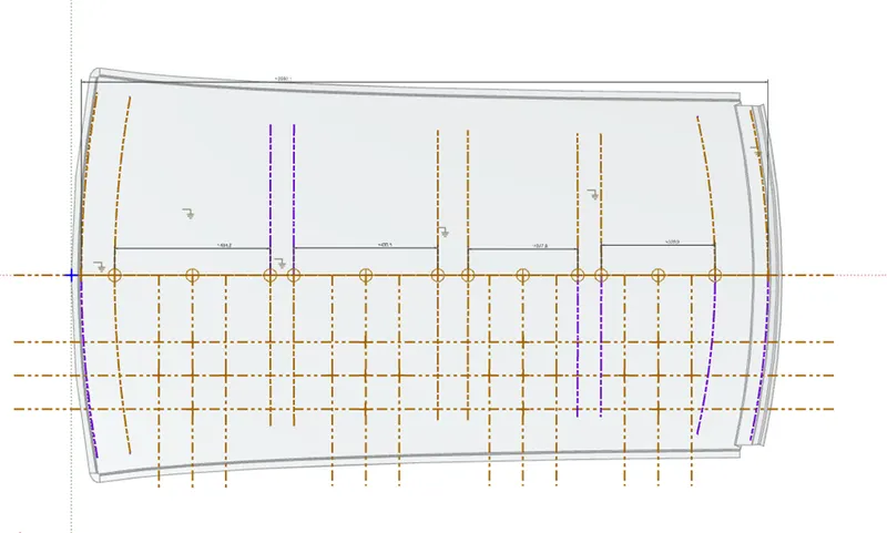
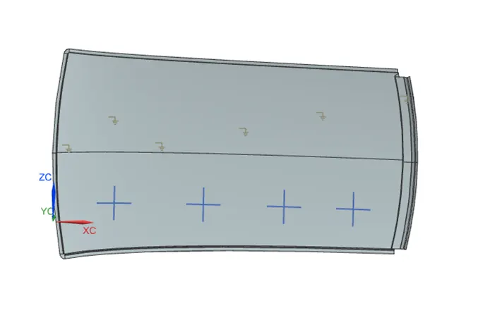
- Draw the sketches and create intersection points and project it on the surface.
- Draw an arcs using the points and find the Rx and Ry values for each case.
- Find all the values and submit all the values in the formula.
|
ROOF RAIL |
L |
R |
T |
I |
W |
RESULT |
|
FRN – BRF 1 |
2050.1 |
3842.66 |
0.75 |
464.8 |
1.742 |
PASS |
|
BRF 1- CTRF |
2050.1 |
5681.36 |
0.75 |
430.5 |
1.1113 |
PASS |
|
CTRF – BRF 2 |
2050.1 |
327.8 |
0.75 |
327.8 |
2.04 |
PASS |
- For the roof component the heat distortion is satisfied in a given judgement.
SNOW LOAD CONDTION:
- This test is done to know how is the roof behaving when there is a snow over. normally due to the snow weight the dent will happen. But the roof should be designed in such a way that when the snow is removal the roof should go it its original position. This is the basic requirements for snow load criteria.
Qr = [Iy x t2] / [α x s x [(Rx + Ry)/2]2 x 10-8]
Note: The Qr value given over here is correct. There was a typo error in the formula given in the video.
Where,
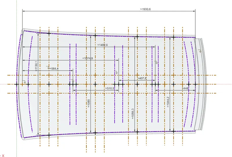
α = My x Lx2 x 10-12, My = Y(Ly-Y)
t = Roof plate thickness [mm]
Ly = Distance between the front and rear roof Rails on the Vehicle along with 0Y[mm]
Length of Roof panel with the center point between Roof rail Front /Rear as the front and rear reference point.
Lx = Distance between the Left and Right end of the roof on the Roof BOW [mm]
The width of the roof panel is exposed on the surface.
Y = Distance front Front Roof Rail to Roof BOW [mm]
s = Distance for which Roof BOW bears divided load [mm]
s = L1/2 + L2/2
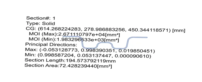
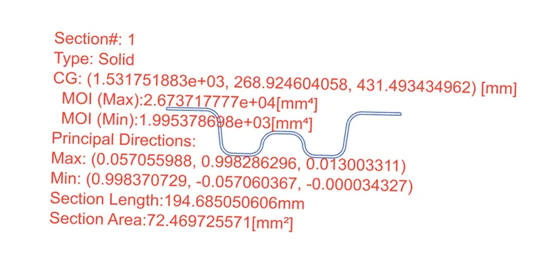
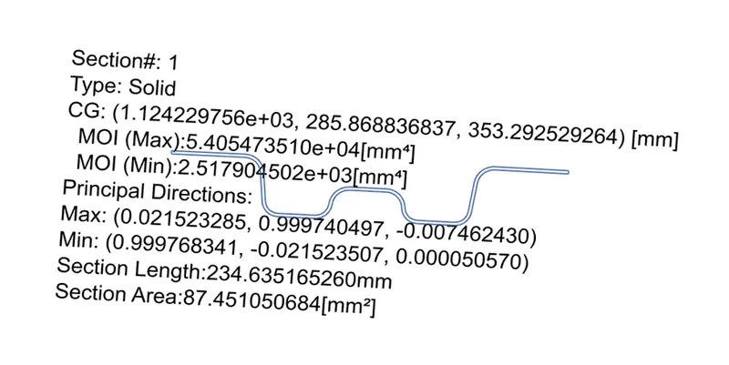
Iy = Geometrical moment of inertia of Roof BOW (Y cross-section) [mm4]
Rx = Lateral direction curvature radius of roof panel Y cross-section on Roof BOW [mm]
Roof panel curvature Radius of the Length Lx in Front view
Ry = Longitudinal Direction curvature radius of the Roof panel X cross-section on Roof BOW [mm]
Roof panel X curvature radius of length s in Side view
Judgment condition
Qr ≥ 3.1
250 ≤ s ≤ 380
BOW ROOF 1:
BOW ROOF 2:
CENTRE ROOF RAIL:
|
Roof Rail |
Lx |
Ly |
Y |
T |
L1 |
L2 |
Rx |
Ry |
My |
alpha |
Iy |
S |
Qr |
Result |
|
FRR – BRF 1 |
1130.1 |
1930.6 |
564.4 |
0.75 |
564.4 |
510.5 |
4306.23 |
2918.80 |
7.71*e5 |
0.984 |
1.983*e3 |
537.45 |
16.16 |
pass |
|
BRF 1 – CTRF |
1080 |
1930.6 |
1074.8 |
0.75 |
510.5 |
407.8 |
3807.44 |
6968.55 |
9.19*e5 |
1.0728 |
2.5179*e3 |
459.15 |
9.9045 |
Pass |
|
CTR F – BRF 2 |
1056.3 |
1930.6 |
1482.6 |
0.75 |
407.8 |
448 |
4290.88 |
11648.57 |
6.642*e5 |
0.741 |
1.9953*e3 |
427.9 |
5.5673 |
pass |
- For the roof component all the values is greater than the given condition so this component is good for snow load criteria.