Roof Design
ROOF:
Roof of the car is one of the most important component .It plays a major role during the roll over of a car in an accident for the safety of the passengers. so it is must to provide the greater strength to the roof and its components. As the roof outer surface needs to pass HDC and SLC conditions ,it is to check whether it can withstand heat on high temperature during summer days and snow load requirements.As per the Institue of highway safety , there are norms to calculate the strength of the roof for the roll over strength test.
Based on the roofs it has three types such as
Hardtops - It is the normal roof ,metal roof which is fully covered .
Sunroof - In this roof there is small portion is open on the outer roof , depend upon the opening of the sunroof it is further classified into types. which is famous on the market nowadays.
Convertible - It can be either used as fully closed and fully opened.
The major components of the Roof assembly Design consists of :
Roof outer surface
Front inner roof rail
Rear inner roof rail
Bow Roofs
Centre Roof rail
The number of bow roof depends upon the length of the roof and in addition to the reinforcements sun roof also provided to the roof assembly.
Design of Outer Roof Surface :
The main conditions we need to consider before the design of the roof assembly is Ditch area has to provide in the front roof rail and rear roof rail. Elements to consider - in front roof for the A-pillar and Windshield , in the rear roof for D-pillar and the back door of the car. And also want to consider for the better visibility both in front and rear.
The strength in the flat surface of the outer roof is lower compared to the curvature of roof outer surface. so only we are providing bow roofs and centre reinforcements to the roof assembly inorder to gain the strength in flat roof surface. 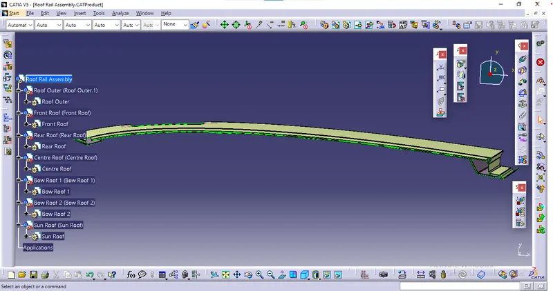
For the mouting of the windshield we need to provide the minimum required distance as per the master sketch and to get the better visibility we need to maintain the headliner line not to exceed the maximum. these are the major parameters consider in outer roof front portion.
Design of Front Inner Roof Rail :
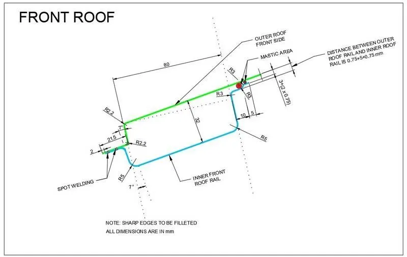
As we seen in the outer roof ,same we need to maintain the head room clearance and the visibilty line in the front inner surface . we will be joining the outer roof and inner front roof by both spot welding process and using mastic glue in the provided mastic regions. ,here for the stronger support we provide to mastic emboss of 5mm and 3mm. The car room light and bracket mount are in the front inner rail. the drafting angle needs to be maintained by 7 degree.
Design of Rear Inner Rail :
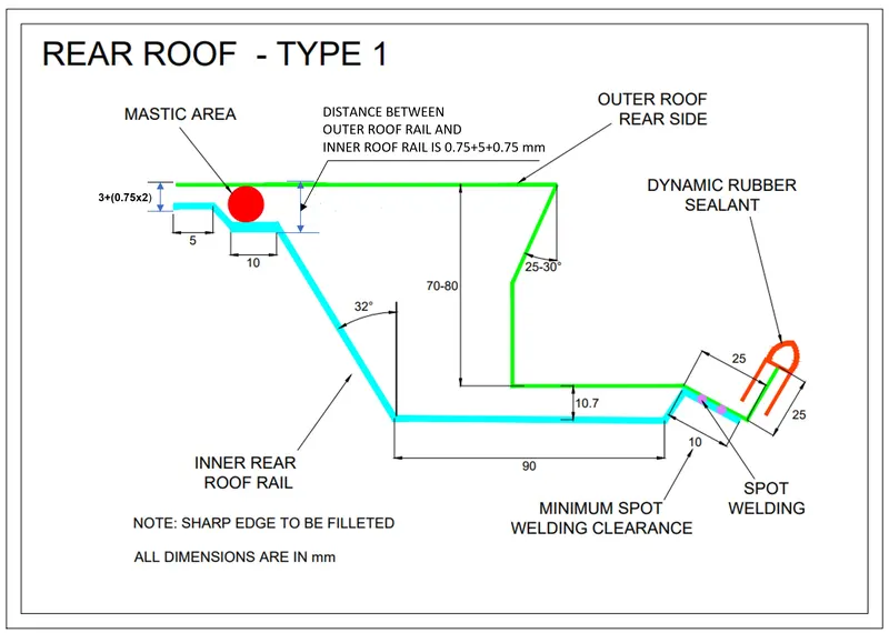
In the rear inner rail, with respect to the parameters given in the master sketch from styling team ,i designed. and for the head room clearance we need to give atleast 85mm from the roof outer surface. Here aslo the inner rear roof and outer roof is joined by spot welding in the outside and inside by using mastic glues in the provided mastic emboss.
Design of Bow Roofs :
Bow roof are designed in the flat surface of the roof outer ,because in that area the strength will be less it can easily lead to any discomfortability, compared to the roof surface having certain curvature of radius.
In this given roof skin i designed two bow roofs, it is majorly depends upon the flat length of the roof, the span of the bow roof is designed as per the master sketch . and mainly the head room clearance has to be maintained in this bow roofs , here i given bow roof flange of distance 20mm from the outer roof surface.
The bow roof is joined to the outer roof by using mastic glue. the mastic emboss is to maintain a clearance of 5mm .
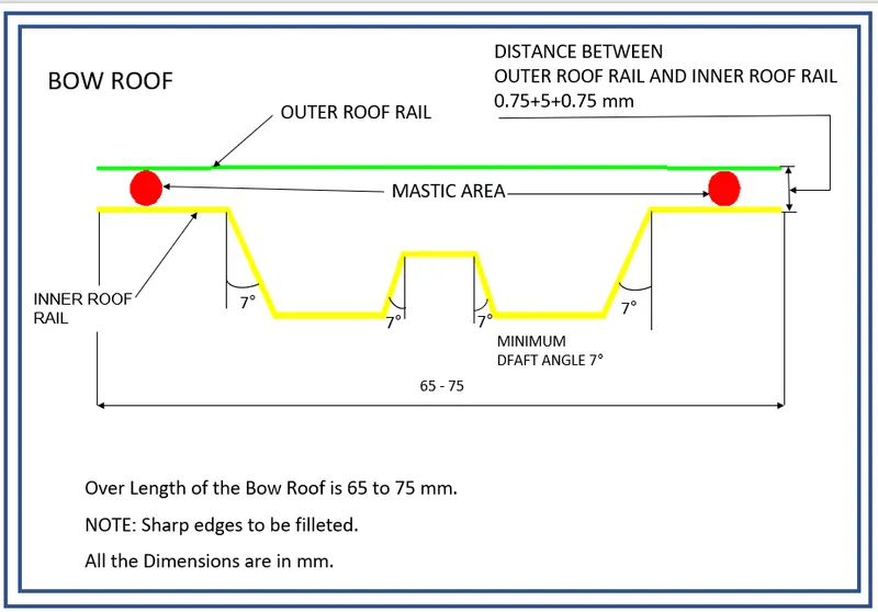
Design of Reinforcements:
Centre roof with sun roof :
The centre reinforcement is also to maintain the strength to the roof surface in the flat region and to mount the reinforcements , here i given the centre roof flange of distance 15mm from the outer roof surface. in order ot maintain the head room clearance for the passenger . the centre roof is joined with the outer surface by using mastic glues .
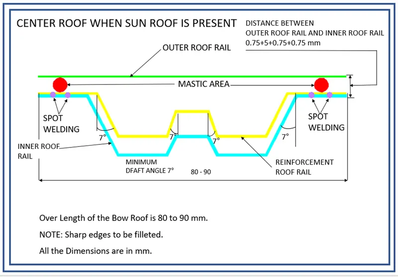
the sun roof is joined to the center reinforcment roof rail with spot welding process.
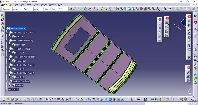
For all Surfaces thickness of 0.75mm is given, for roof outer surface thickness is given inwards and for Front rail,rear rail,bow roof rail & reinforcements rails thickness is given outwards.
DRAFTING ANALYSIS :
The draft analysis is mainly done to check whether our designed part is opted to manufacturing . it is analysed by the draft angle with the part at kept 90degree(perpendicularity) to the tooling angle . here we maintained draft angle of 7degree. the tool should not project outside the part . so it is necessary to maintain the draft angle.
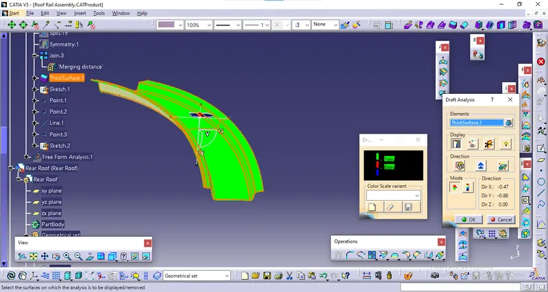
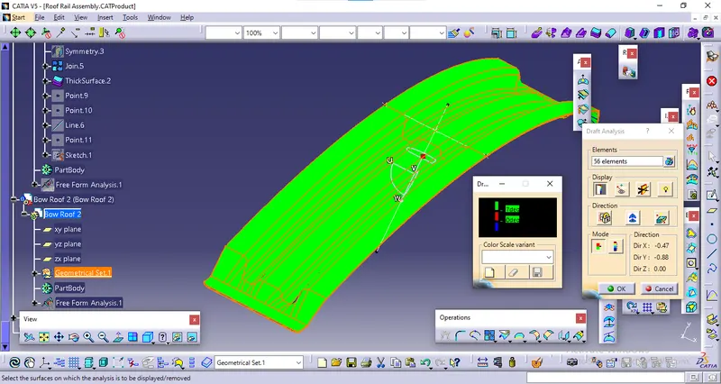
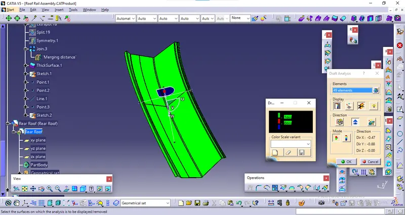
BOW ROOF CALCULATION :
HEAT DISTORTION CRITERIA :
It is to determine whether the designed satisfy the condition , so that the roof can withstand high temperature .
Heat distortion formula,
W = [1.73 x 10^(-3) x L] + [1.85 x 10^(-8) x (R^2)/t] + [ 1.10x10^(-3) x l] - 2.68
Where,
L = Roof Length in X-Direction[mm](Roof dimension in 0-Y)
R = Roof curvature
R = 2(Rx*Ry)/(Rx+Ry)
Rx = X curvature
Ry = Y curvature
t = Roof plate thickness [mm]
l = Bow Roof Span [mm]
we need to calculate as per the sample shown in the below image.
The 'W' value should be less than 2.7 , it is the satisfy condition of HDC.
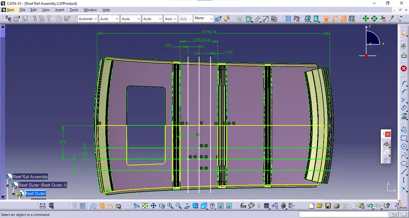
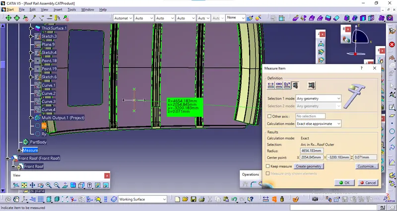
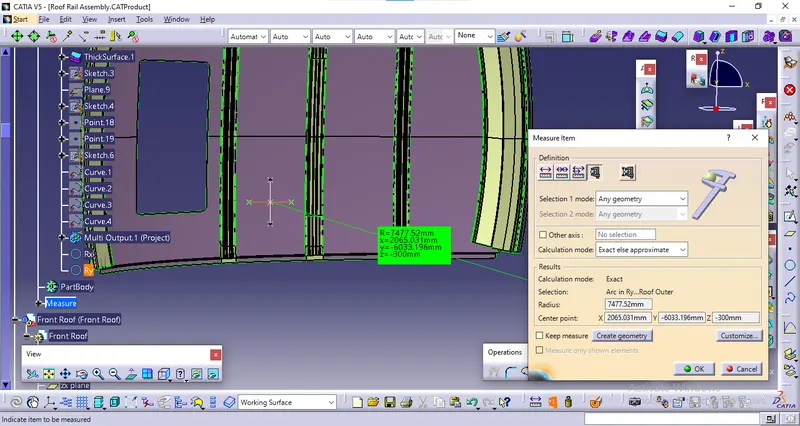
As shown in the above image we need to carryout the same procedures to get the values and input to the formula ,then check with results and tabulate them.from the centre 0Y line 300mm offset and then from that 100mm offset in both directions and from the middle points of the bow span same 100mm offset from both sides. by intersecting the lines we get the required Rx and Ry.
| Bows | Rx | Ry | R | l | L | t | R^2/t | W | Result |
| Case 1 (bow roof 1 to CTR) | 4654.183 | 7477.52 | 5737.322 | 335.324 | 2078.78 | 0.75 | 43889151.64 | 2.096 | ok |
| Case 2 (CTR to bow roof 2) | 3894.865 | 11001.561 | 5753.003 | 334.167 | 2078.78 | 0.75 | 44129391.35 | 2.1002 | ok |
| Case 3 (bow roof 2 to Rear roof rail) | 3245.414 | 14811.832 | 5324.236 | 345.072 | 2078.78 | 0.75 | 37796651.97 | 1.995 | ok |
as we see now in the bow roof between front rail and first bow there is sunroof so i not done curvature study on there, other than that all 3 cases satisfy the HDC condition as the W value is lesser than the Judgement condition value 2.7
SNOW LOAD CALCULATION :
Qr = [Iy x t2] / [α x s x [(Rx + Ry)/2]2 x 10-8]
Where,
α = My x Lx2 x 10-12 , My = Y(Ly-Y)
t = Roof plate thickness [mm]
Ly = Distance between the front and rear roof Rails on the Vehicle along with 0Y[mm]
Length of Roof panel with the center point between Roof rail Front /Rear as the front and rear reference point.
Lx = Distance between the Left and Right end of the roof on the Roof BOW [mm]
The width of the roof panel is exposed on the surface.
Y = Distance front Front Roof Rail to Roof BOW[mm]
s = Distance for which Roof BOW bears divided load [mm]
s = L1/2 + L2/2
Iy = Geometrical moment of inertia of Roof BOW (Y cross-section )[mm4]
Rx = Lateral direction curvature radius of roof panel Y cross-section on Roof BOW [mm]
Roof panel curvature Radius of the Length Lx in Front view
Ry = Longitudinal Direction curvature radius of the Roof panel X cross-section on Roof BOW [mm]
Roof panel X curvature radius of length s in Side view
As we need to check whether the value of Qr is greater than or equal to 3.1 , that is the ok criteria.
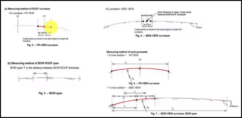
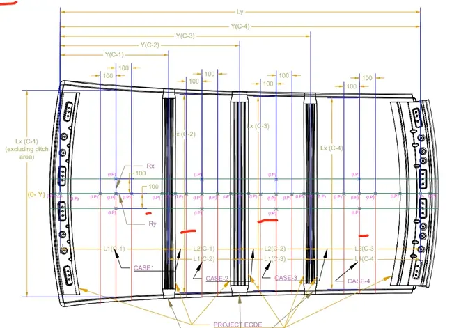
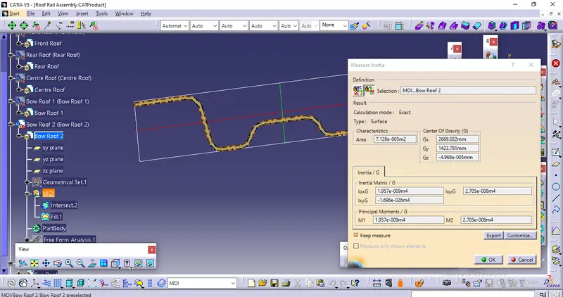
With refernce to the sample images given above we need to get the required values for the calculation and input them in the table with the results below.
| Bow | Iy | a | Lx | Ly | Y | s | Rx | Ry | t | Qr | Result |
| Case 1 (bow roof 1 to CTR) | 1.95x10^3 | 1.12771 | 1089.323 | 1960.498 | 1089.897 | 409.697 | 3876.976 | 7473.912 | 0.75 | 9.827 | ok |
| Case 2 (CTR to bow roof 2) | 8.274x10^2 | 0.799197 | 1069.271 | 1960.498 | 1491.997 | 438.8 | 4308.037 | 11603.767 | 0.75 | 2.97 | not ok |
as from the above results it is noted that case 2 is not satisfying the judgement criteria the Qr value is less than 3.1 , so far increaing that we can create emboss on the roof outer flat surface rather than increasing the thickness of the roof surface ,creating emboss on the outer roof is a valued suggestion.
ROLL OVER TEST : ROOF LOAD TEST
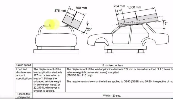
This test is to determine the strength of withstand of the roof on applying load gradually on its surface at inclined angle of 25degree.its a crush load strength test. From this we able to get the load -displacement graph . As per the recommendation and norms from the Institue of Highway Safety (GS40 & SAS0)
Displacement of load application device is 127mm or less when a load of 1.5 times the weight of the vehicle is applied and the crush speed is maximum to be 13mm/sec. Time to complete the test is within 120 secs.