Roof Design
INTRODUCTION
An automobile roof is the portion of an automobile that sits above the passenger compartment, protecting the vehicle occupants from sun, wind, rain, and other external elements. In design point of view, it is not so easy to design. Because several support rails should be designed for enough strength to withstand the load. Bow roofs are primarily fixed in flatter region to enhance strength. Front roof and Rear roof rails are fixed to the ditch area using spot weld operation. whereas front bow, rear bow and center roof rails are fixed to roof using mastic sealants.
TESTING OF ROOF:
Roof strength evaluations are conducted on a quasi-static test system. The system consists of an upright assembly and an attached loading head that can be fixed at varying heights from the ground. It also mounted at pitch angles ranging from −5 to +5 degrees to accommodate testing on the driver or passenger side. The roll angle is permanently fixed at 25 degrees. Four hydraulic actuators control the movement of the plate along two linear guides. The entire system is mounted on a T-slot bed plate anchored to the floor of the test facility.
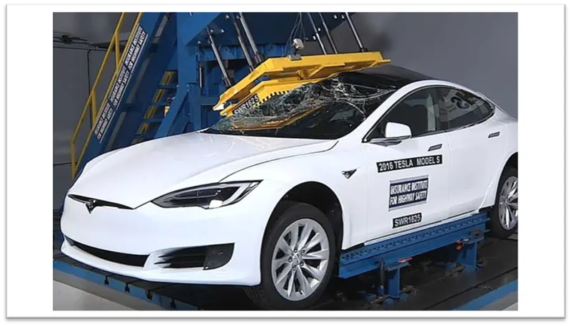
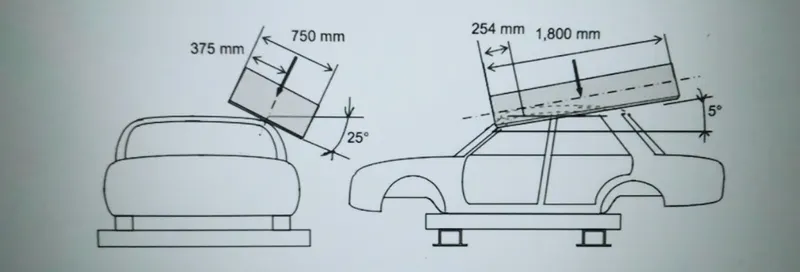
The load is applied to 5 degrees tilted from the front end to the rear end while the load will be in 1800 mm in length and 750 mm in width . The load is applied at the position of 25 degrees from the flatness of the roof . The load is applied on the roof for almost 120 sec and the crush speed at which the load applied is 13 mm/sec.
HEAT DISTORTION STUDY:
Heat distortion temperature is a temperature limit above which the sheet material cannot be used for the structural applications . This study is used to predict the temperature at which the sheet starts to soften when it is exposed to a fixed load at an elevated temperature.
Bow–Roof Prediction Formula :
W = [1.73 x 10^(-3) x L] + [1.85 x 10^(-8) x (R^2)/t] + [ 1.10x10^(-3) x l] - 2.68
Where,
L = Roof Length in X-Direction[mm](Roof dimension in 0-Y)
R = Roof curvature
R = 2(Rx*Ry)/(Rx+Ry)
Rx = X curvature
Ry = Y curvature
t = Roof plate thickness [mm]
l = Bow Roof Span [mm]
Judgment Condition
OK< 2.7
Thickness for the Roof(t):
Roof Outer Panel, t= 0.75mm
Front Roof Rail, t = 0.75mm
Rear Roof Rail, t = 0.75mm
Bow Roof Rail Front, t = 0.75mm
Bow Roof Rail Rear, t = 0.75mm
Reinforcement roof rail, t = 0.75mm
ROOF LENGTH (L):
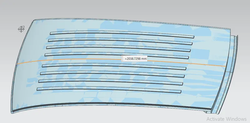
L = 2038.7298 mm
BOW ROOF SPAN (I):
Take the distance from front roof rail to bow roof front for finding the bow roof span(I), in order to measure another bow roof span.
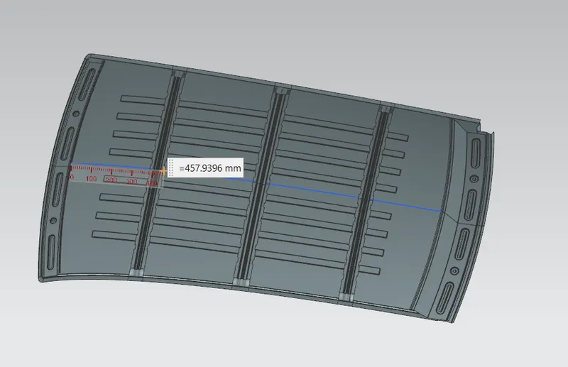
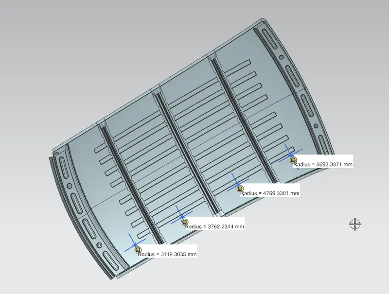
RX Value:
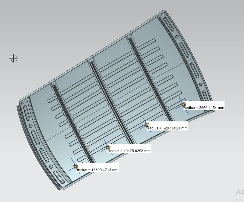
RY Value:
| Rx (mm) | Ry (mm) | Rx * Ry | Rx + Ry | R (mm) | L | t (mm) | I (mm) | W | Result | |
| Front roof - Bow Front | 5692.3371 | 2666.4154 | 15178135.31 | 8358.753 | 3631.675 | 2038.7298 | 0.75 | 457.9396 | 1.676066 | OK |
| Bow Front - Centre Roof | 4769.3301 | 6297.6021 | 30035343.25 | 11066.93 | 5427.944 | 2038.7298 | 0.75 | 431.4950 | 2.048391 | OK |
| Center roof - Bow Rear | 3762.2344 | 10475.6298 | 39411774.8 | 14237.86 | 5536.192 | 2038.7298 | 0.75 | 431.6060 | 2.077788 | OK |
| Bow Rear - Rear Roof | 3119.3035 | 13899.4713 | 43356669.47 | 17018.77 | 5095.158 | 2038.7298 | 0.75 | 328.4230 | 1.84863 | OK |
From the above table, all the values are satisfying the condition; W< 2.7 and also W> 3.1. So it is finalised that all the bow roofs areas are placed at the right place.
SNOW LOAD:
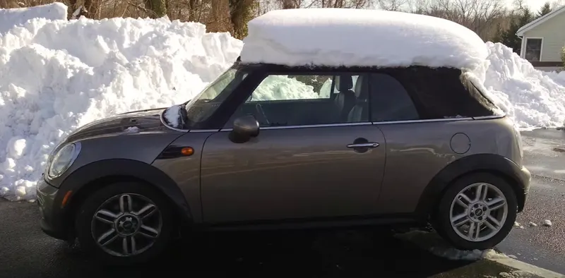
Snow load criteria study checks the durability of the roof to withstand the snow fall on it. Also the roof should reflex back to its original shape without any permanent deformation after load (snow) being removed.
SNOW LOAD CRITERIA:
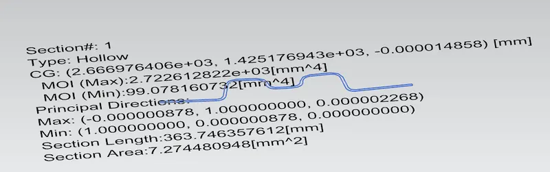
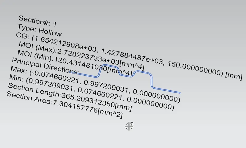
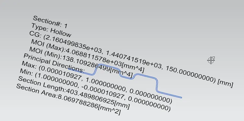
Qr = [IY x t2] / [α x s x [(RX + RY)/2]2 x 10-8]
Where,
α = My x LX2 x10-12, My = Y(Ly–Y)
Judgement condition = Qr ≥3.1
250 ≤s ≤ 380
t = Roof plate thickness[mm]
LY = Distance between the front and rear roof rails on the vehicle along with 0Y[MM],
Length of roof panel with the center point between roof rails front/ rear as the front and rear reference point.
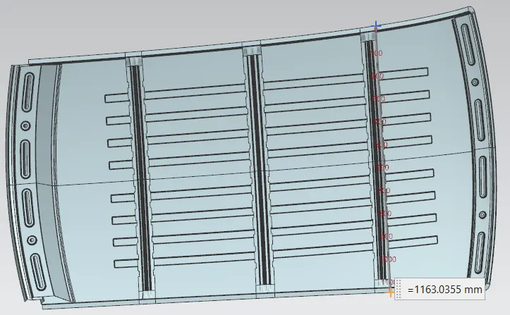
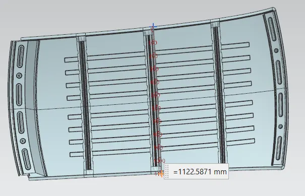
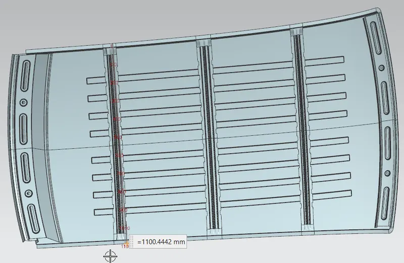
LX= Distance between the left and right end of the roof on the roof bow[mm],
With of the roof panel exposed on the surface.
Y = Distance between Front roof rails to roof bow [mm],
s = Distance for which roof bow bears divided load [mm],
s = L1/2 + L2/2
Iy = Geometrical moment of inertia of roof bow (Y cross – section) [mm4],
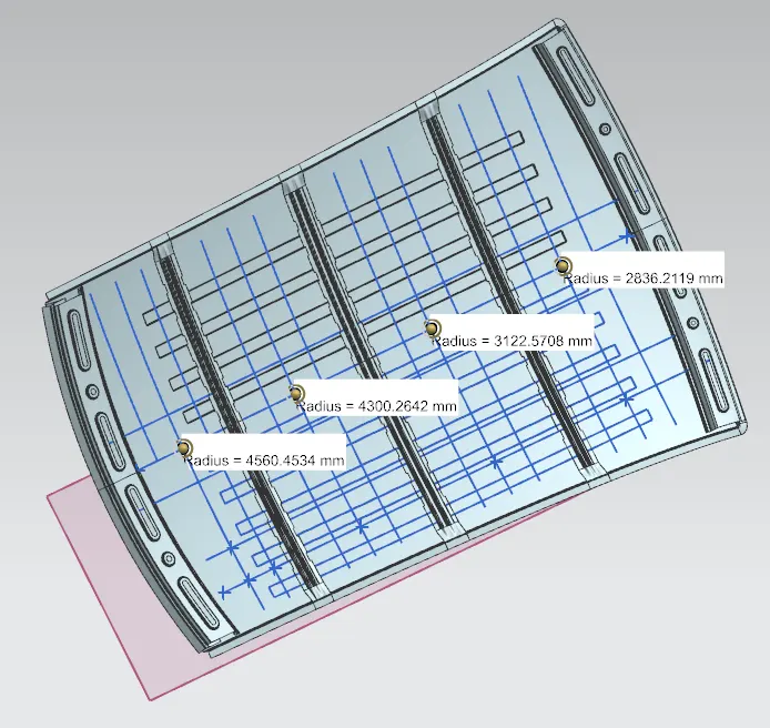
RX = Lateral direction curvature radius of roof panel Y cross section on roof bow [mm4],
Roof panel curvature radius of the length LX in front view.
RY = Longitudinal direction curvature radius of the roof panel X cross section on roof bow[mm4],
Roof panel X curvature radius of length s in side view.
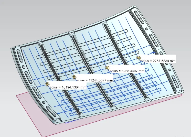
RX Value:
Ry Value:
LY Value:
LX1 Value:
LX2 Value:
LX3 Value:
Calculating the Moment of Inertia :
Rear Bow :
Front Bow:
Central Reinforcement Rail:
FINAL RESULTS OF SNOW LOAD CRITERIA:
With the values, the Snow load value(W)is tabulated and calculated:
| IX | LX | LY | L1 | L2 | Rx | RY | t | y | S | MY | ((Rx+Ry)/2)^2 | α | Qr | Result | |
| Front roof - front bow | 2728.2 | 1163.04 | 2038.73 | 422.26 | 506.63 | 2757.5839 | 2836.2119 | 0.75 | 422.26 | 464.445 | 682570.6 | 7822637.86302441 | 0.923287341332137 | 45.75 | OK |
| Bow Front - CRR | 4068.8 | 1122.59 | 2038.73 | 506.60 | 506.80 | 6265.4407 | 3122.5708 | 0.75 | 506.60 | 506.7 | 776177.1 | 22033689.9810331 | 0.978144829976964 | 20.96 | OK |
| CRR- Rear Bow | 2722.6 | 1100.44 | 2038.73 | 506.78 | 363.45 | 16194.1364 | 4560.4534 | 0.75 | 506.78 | 435.115 | 776361.6 | 107688249.441566 | 0.940149204332406 | 3.48 | OK |
Thus the Qr value should be greater than 3.1. And here all the three satisfies the condition.
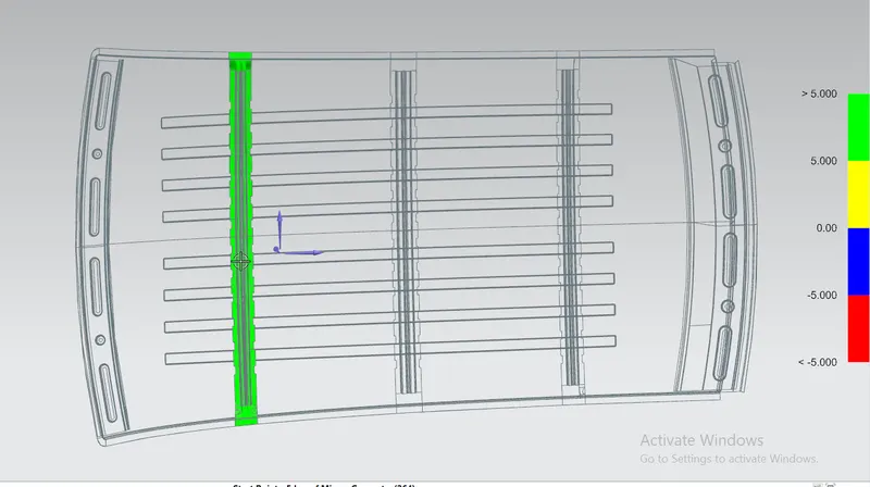
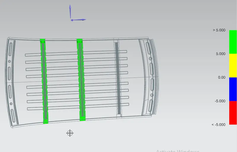
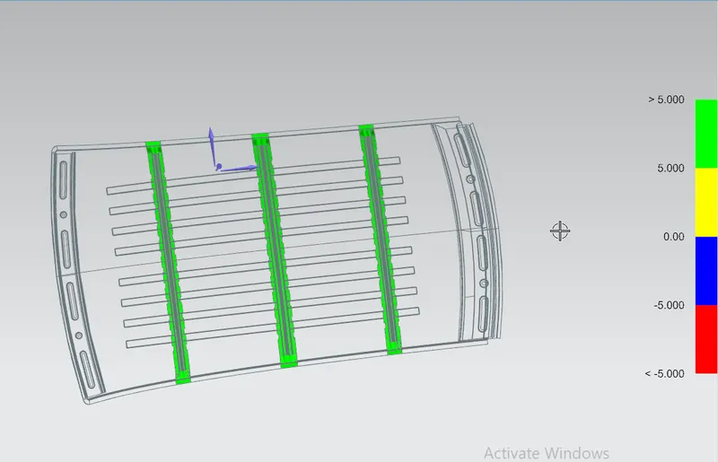
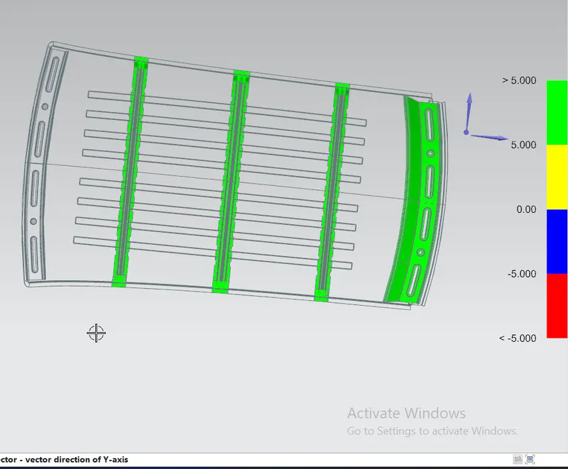
Draft Analysis:
Front Bow:
CRR:
Rear Bow:
Rear End Rail:
Front End Rail:
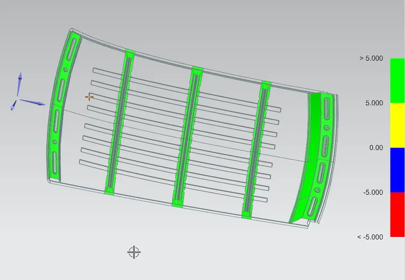
Top Body Roof:
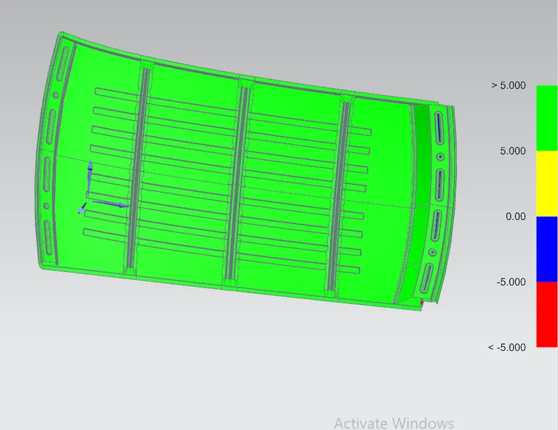
Thus the draft analysis is done which shows the components can be drafted to the minimum angle without any fatigue. Thus the parts are manufacturable.