Roof Design
Aim:
To a given roof styling, create essential flanges and reinforcement.
Objective:
- To design the automotive roof based on the given styling surface and to analyze the prepared model to check the manufacturability and the feasibility of the design.
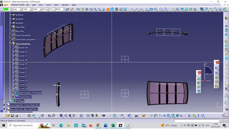
- To perform the section modulus study for the master sections and create for front roof rail, Bow roofs and center roof rail.
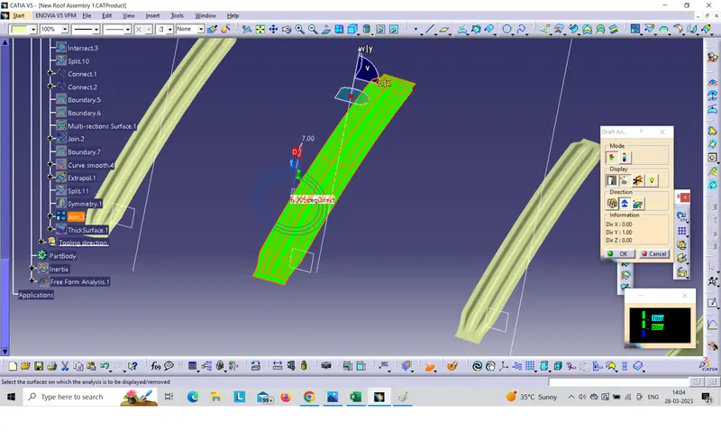
- To create the Ditch area and to perform the draft analysis.
Introduction to Roof:
An automotive roof or car top is the portion of the automobile that sits above the passenger compartment, protecting the vehicle occupants from Sun, Wind, Rain and other external element.
Under the styling surfaces that’s is seen from the outside, there are many other structures under the roof that contributes to its strength and stability. The number of such reinforcement structures/supports differ with respect to the size of the vehicle. They are primarily installed on the flatter areas of the roof to enhance the strength.
They are the Front Roof Rail, Rear Roof Rail, Center Rail and Bow Roof Design which are given Mastics and spot welded to the roof flanges & ditch are and improve NVH value by increasing the strength of the roof of using mastics sealants.
Types of Car Roofs:
- Convertible roofs.
- Hard Tops
- Sun roofs.
- T- Tops.
- Target tops.
- Vinyl roofs.
Design Consideration of roof:
- Visibility Criteria
- Head Clearance
- Curvature Study
- Heat Distortion and snow load criteria
- Draft Analysis
- Safety Parameters
Roof Crush test for passenger car:
Safety point of view vehicle roof plays a very crucial role especially roll over kind of accidents, In which vehicle tips over onto its side of the roof Vehicle rollover crashes are the cause of many fatalities and head, neck and spine trauma around the world.
Strength of the roof structure to occupant protection in real world roll over crashes, requiring the maximum moving distance of the roof structures should be less than 127 mm, (5 in), where the induced load is 1.5 times the vehicle weight.
For the test, the passenger ca shall be rigidly placed or positioned on a horizontal surface with the doors locked and the window closed. Furthermore, a flat, rigid block with a lower surface a rectangle measuring 30 inches wide by 72 inches long (762mm x 1829 mm) shall not move more than 5 inches (127mm), measured as the distances between the original location of the lower surface of the test device and its location as the specified force level is reached, when it is used to apply a forces of 1.5 times the unload vehicle weight (UVW) or 5000 lbs. (22224N), whichever is less. To either side or forward edge of the vehicle.
Joining Process:
Mastics are introduced between the roof outer panel and the reinforcements for joining. Where ever the mastics are introduced there is remarkable strength. Spot welding is also introduced to join the reinforcement and the outer panel.
Reinforcement and its types:
If the roof is flat, it is weak and cannot able to with stand the external load like snow load, roll over and etc. so in order to increase the strength of the roof, reinforcement like front roof rail, central roof rail, rear roof rail and the bow roof are introduced and joined in the flat surface of the roof with different joining process. In general, there are four types of reinforcement are used in the hard roof top they are,
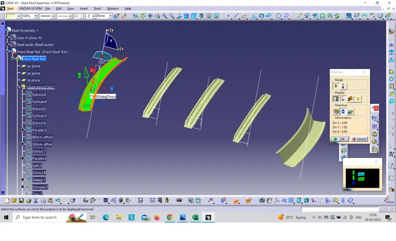
- Front roof rail
- Central Roof rail
- Rear roof rail
- Bow roof rail
Section Modulus:
Section Modulus is a geometric property for a given cross section used in the design of beams or flexural members. Other geometric properties used in design include area for tension and shear, radius of gyration for compression, and moment of inertia and polar moment of inertia for stiffness. Any relationship between these properties is highly dependent on the shape in question. Equation for the section moduli of common shapes are given below.
There are two types of section moduli:
The elastic section modulus and
The plastic section modulus.
The elastic section modulus is defined as
S = I / Y
Where:
S = Section modulus
I = second moment of inertia (or area moment of inertia, not to be confused with moment of inertia)
Y = distance from the neutral axis to any given fiber. It is often reported using Y = C, where c is the distance from the neutral axis to the most extreme fibre.