Roof Design
OBJECTIVE
The main objective of the project is to develop the car roof design and the its reinforcements from the given Styling surface
INTRODUCTION
An Automobile roof is the part of a vehicle/car which is located at the top of the passenger compartment.The roof protects the vehicle from the wind,sun,rain and other external occupants.
The roof is actually made in some tilted in structure,it is not made flat.The main logic behind the tilted surface is that it will be having high strength comparing to the flat surface.
The reinforcements are also made inorder to strengthen the roof and thus able to withstand the overhead forces like snow
The reinforcements that are in the Automotive roof are:
- Front roof rail
- Rail roof rail
- Center roof rail
- Bow roof 1
- Bow roof 2
DESIGN CONSIDERATION OF THE ROOF
- Visibility
- Head clearence
- Curvature study
- Heat distortion and Snow Load Criteria
MANUFACTURING TECHNIQUE
The car's roof is generally made from the Sheetmetal part.A metal is coverted into the sheetmetal by the rolling process.The sheetmetal is converted into the desired shapes by the stamping process.The joining technique is done by the mastic ceilings and in some areas the spotwelding is used.The manufacturing of the emboss is done by the punching which will increase the strength of the panel.
ROOF CRUSH TEST
The Roof crush test is done to verify how much strength the roof can withstand.It is done by the Insurance Institute of Highway and Safety.IIHS will give the rating for the roof crush test.
Roof strength evaluations consist of a quasi-static test conducted on a vehicle’s roof in a manner similar
to tests used to judge compliance with U.S. Federal Motor Vehicle Safety Standard (FMVSS) 216 (Office
of the Federal Register, 2009). The main differences between the IIHS roof strength test and that specified
by FMVSS 216 are that the IIHS test:
• Specifies testing one side of a vehicle’s roof,
• Does not include a headroom criterion,
• Specifies testing to a given displacement instead of a given force level, and
• Specifies setting the vehicle’s pitch angle during testing based on the measured on-road pitch
angle
TEST VEHICLE PREPARATION
With the vehicle on a level surface, the on-road pitch angle at the front door sill is measured on both sides
of the vehicle. Unless the vehicle manufacturer requests otherwise, roof racks and other nonstructural
items that may be contacted during the test are left as installed from the factory. Any trim or other
components are removed if they interfere with supporting the vehicle along its rocker panels.
TESTING
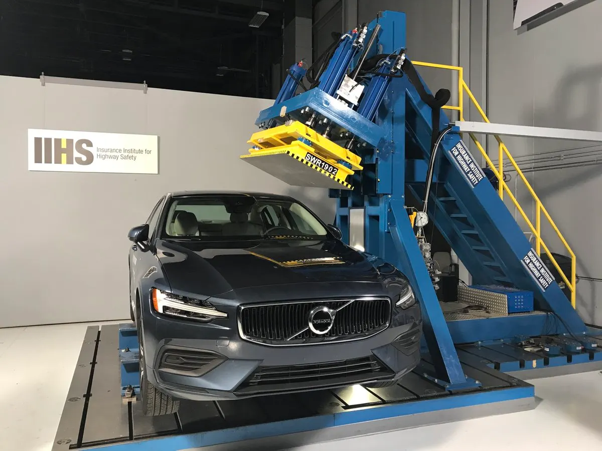
Roof strength evaluations are conducted on a quasi-static test system manufactured by MGA Research
Corporation (Figure 3).
The system consists of an upright assembly and an attached loading head that can be fixed at varying
heights from the ground and at pitch angles ranging from −5 to +5 degrees to accommodate testing on the
driver or passenger side.
The roll angle is permanently fixed at 25 degrees.
Four hydraulic actuators control the movement of the platen along two linear guides.
The entire system is mounted on a T-slot bed plate anchored to the floor of the test facility.
CALCULATING THE STRENGTH-TO-WEIGHT RATIO (SWR) RATING
Force and displacement data are recorded for 5 seconds prior to each test, while the test system holds the
loading platen at initial roof contact. The data recorded from 1 to 4 seconds of this hold time are averaged
for each channel to produce a measurement offset that is subtracted from the data recorded during the
crushing of the roof. After removing the offset for each channel, the force-displacement curve is plotted
using the summed output from the five load cells and the average displacement from the four LVDTs.
The maximum force prior to 127 mm of platen displacement is divided by the measured curb weight to
obtain the SWR. Both the force and curb weight are rounded to the nearest pound prior to performing the
calculation, and the resulting SWR is rounded to the nearest one-hundredth of a unit. Displacement is
rounded to the nearest 0.1 mm. (The maximum displacement where the load can be used for the vehicle
rating is 126.9 mm.) The vehicle’s rating is assigned based on the boundaries listed in Table 1.
Table 1
Roof Strength Rating Boundaries
SWR Rating
≥ 4.00 Good
≥ 3.25 to < 4.00 Acceptable
≥ 2.50 to < 3.25 Marginal
<2.50 Poor
All trim levels sharing the tested vehicle’s body type and roof structure are assigned the same rating as the
typically equipped trim level, provided their curb weights do not exceed 110% of the selected vehicle’s
weight. Based on published curb weights from multiple sources, any trim levels that may exceed this
weight are identified and weighed. If the weight does exceed 110% of the weight of the selected vehicle, a
unique SWR is calculated for that trim level. If this SWR results in a lower rating, both ratings are
reported for the model, with a split according to trim level. If a trim level weighs more than 110% of the
typically equipped model, but the lower SWR does not fall in a lower rating band, only the original SWR
and rating are reported for the model
FINAL DRAWING
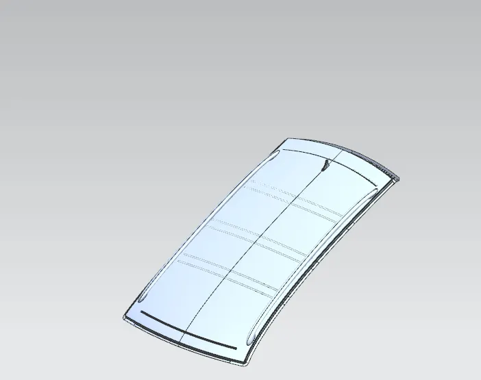
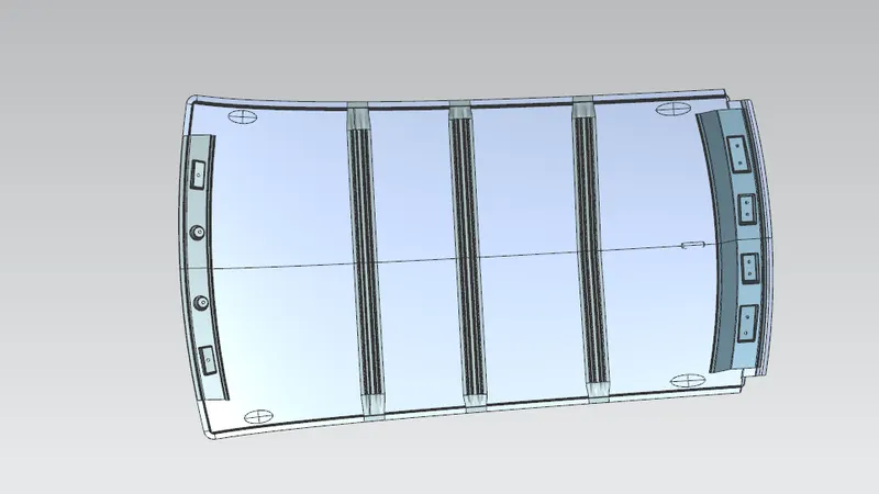
Front roof rail
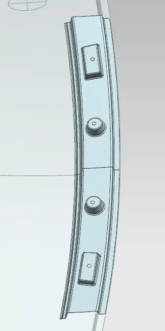
Rear roof rail
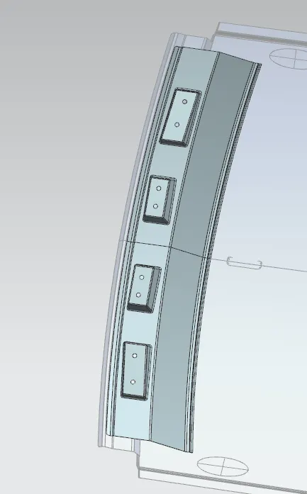
Center Bow Roof
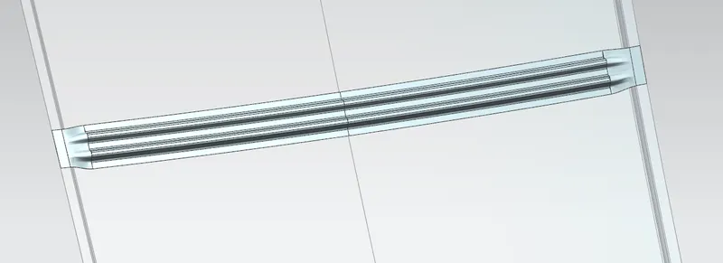
Bow Roof 1
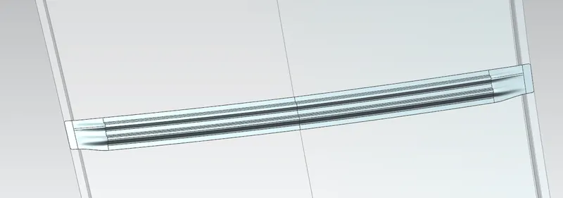
Bow Roof 2
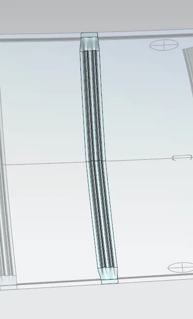
HEAT DISTORTION CRITERIA:
W = [1.73 x 10^(-3) x L] + [1.85 x 10^(-8) x (R^2)/2] + [1.10 x 10^(-3) x I]-2.68
Judgement Condition: OK<2.7>3.1
Where,
L= Roof Length in X- direction [mm](Roof Dimension in 0-Y)
R = Roof curvature
R = 2(RX*RY)/(RX+RY)
RX = X Curvature
RY = Y Curvature
t = Roof plate thickness [mm]
I = Bow roof span [mm]
Thickness for the Roof(t):
Roof Outer Panel, t= 0.75mm
Front Roof Rail, t = 0.75mm
Rear Roof Rail, t = 0.75mm
Bow Roof Rail Front, t = 0.75mm
Bow Roof Rail Rear, t = 0.75mm
Reinforcement roof rail, t = 0.75mm
When the radiation from the sun is hit on the outer surface of the roof the kinetic energy will impact into the roof.Thus the closed bonds will breaks.Thus the strength will decreases.
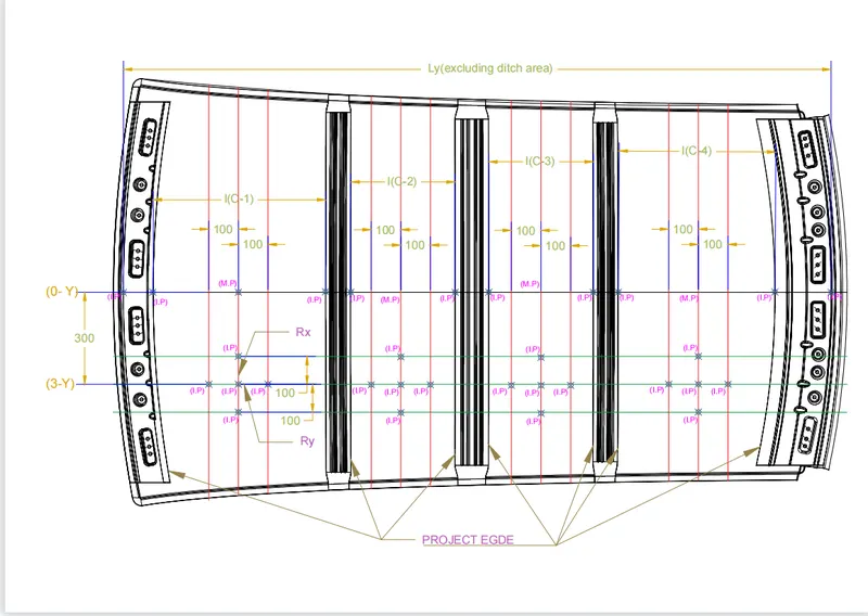
Steps for doing Heat Distortion Criteria in Software
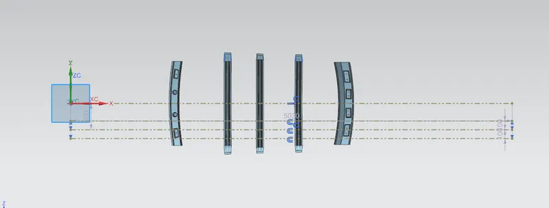
Draw a horizontal line from the middle.Take a offset 300 mm in the downward direction.From that line,take offset of 100mm symmetric.
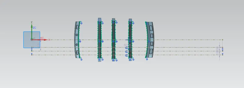
Project the all edges of the roof using project curve option
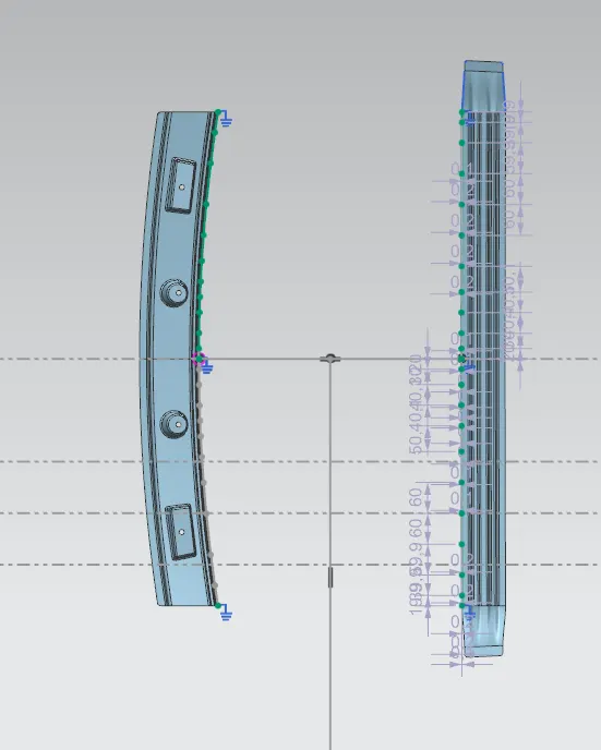
Take the intersection between the project curve and the horizontal line.From the middle of that line,draw another line downwards
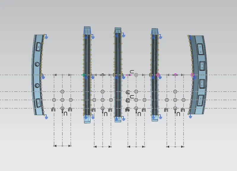
From the middle line,offset 100mm in both the directions.And take the intersection points as shown in the above figure
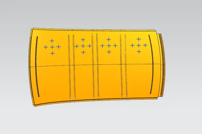
Project these intersection points and join them using intersection curve.Measure the Rx and Ry values.
| SECTION | Rx | Ry | R | t | L | l | W |
| FRR-BW1 | 5700.4 | 2959.1 | 3895.849331 | 0.75 | 2034 | 510 | 1.774201836 |
| RRL | 4825 | 6788.75 | 5640.851362 | 0.75 | 2034 | 283.7 | 1.935763701 |
| BRL-1 | 4047.8 | 10225.7 | 5799.781197 | 0.75 | 2034 | 352.6 | 2.056404061 |
| BRL-2 | 3326.2 | 14287 | 5396.11421 | 0.75 | 2034 | 414.6 | 2.013125198 |
From the table we can get into the conclusion that all the values of W are less than 2.7.So,all the values are acceptable.
SNOW LOAD:
Snow load criteria study is used to check the durability of the roof to withstand the snow fall on the roof and reflex it is original shape without any permanent deformation after load being removed.
SNOW LOAD CRITERIA:
Qr = [IY x t2] / [α x s x [(RX + RY)/2]2 x 10-8]
Where,
α = My x LX2 x10-12, My = Y(Ly–Y)
Judgement condition = Qr > 3.1
250 < s < 380
t = Roof plate thickness[mm]
LY = Distance between the front and rear roof rails on the vehicle along with 0Y[MM],
Length of roof panel with the center point between roof rails front/ rear as the front and rear reference point.
LX= Distance between the left and right end of the roof on the roof bow[mm],
With of the roof panel exposed on the surface.
Y = Distance between Front roof rails to roof bow [mm],
s = Distance for which roof bow bears divided load [mm],
s = L1/2 + L2/2
Iy = Geometrical moment of inertia of roof bow (Y cross – section) [mm4],
RX = Lateral direction curvature radius of roof panel Y cross section on roof bow [mm4],
Roof panel curvature radius of the length LX in front view.
RY = Longitudinal direction curvature radius of the roof panel X cross section on roof bow[mm4],
Roof panel X curvature radius of length s in side view.
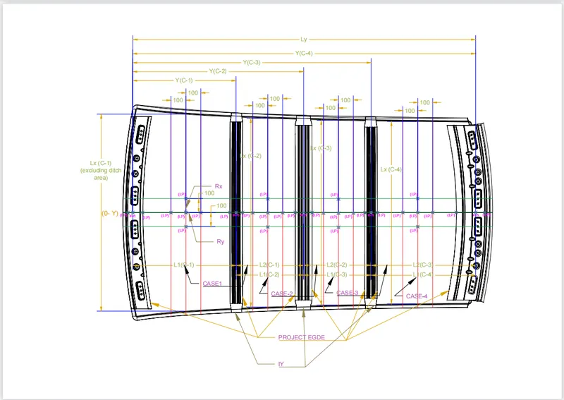
Steps
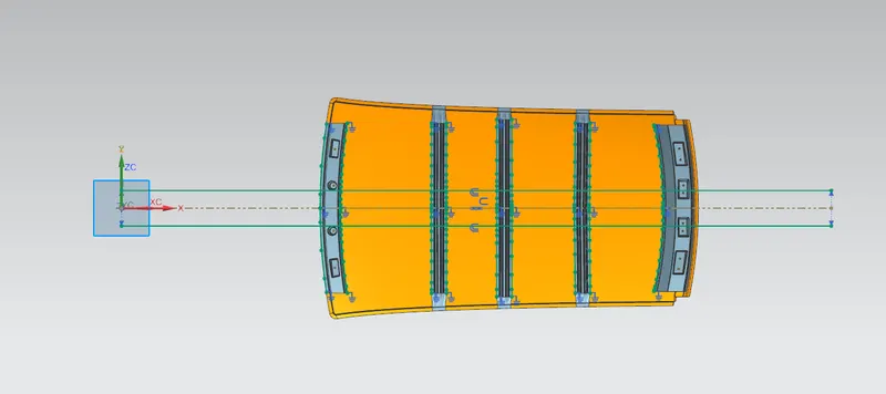
First draw a X-Y line and offset 100mm on top and bottom.Project the all edges of the center roof and the bowroofs.
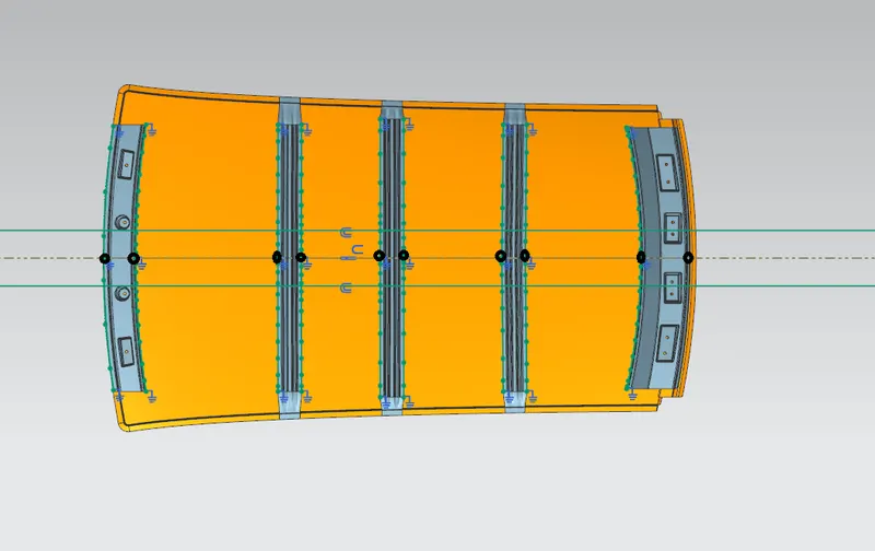
Take the intersection between the the x-y line and the edges of the roofs
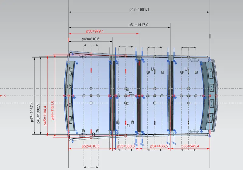
Offset the x-y line bothsides as 100mm.And take the intersection points on the joining areas.Measure the Rx,Ry,Lx,Ly..values
| SECTION | Rx | Ry | Lx | Ly | Y | My | a | L1 | L2 | S | Iy | Qr |
| FRR-BW1 | 4297.4 | 2976.4 | 1151.6 | 1961 | 610.6 | 824554.24 | 1.093509453 | 610.5 | 368.6 | 489.55 | 2048 | 16.26934852 |
| RRL | 3803.4 | 6719.8 | 1104.4 | 1961 | 979.1 | 961378.29 | 1.172592485 | 368.6 | 436.5 | 402.55 | 2044 | 8.798341668 |
| BRL-1 | 4226 | 10647.3 | 1082.5 | 1961 | 1417 | 770848 | 0.9032845042 | 436.5 | 545.4 | 490.95 | 2208 | 5.064132812 |
It is noticed the value obtained Qr > 3.1
DRAFT ANALYSIS
Front roof rail
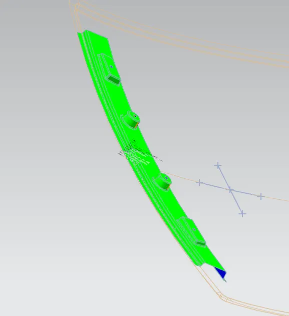
Rear roof rail
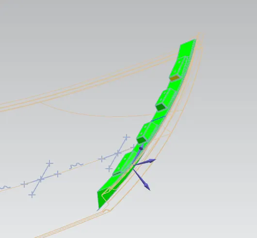
Center roof rail
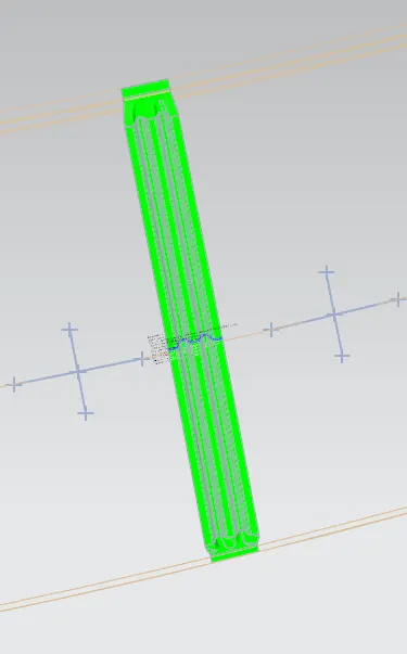
Bow roof 1
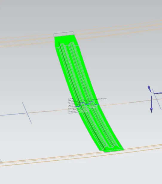
Bow roof 2
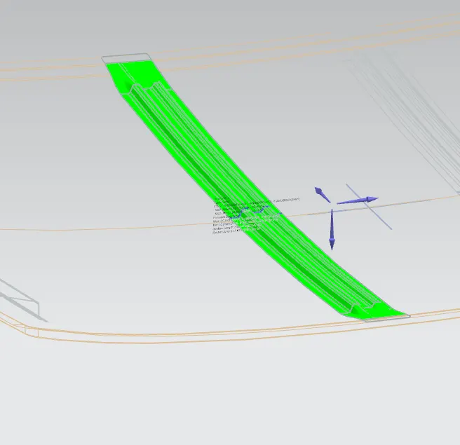
CONCLUSION
The Automotive roof is made according to the given master section,design consideration and manufacturing easibilities.