Roof Design
DESIGN OF CAR ROOF:-
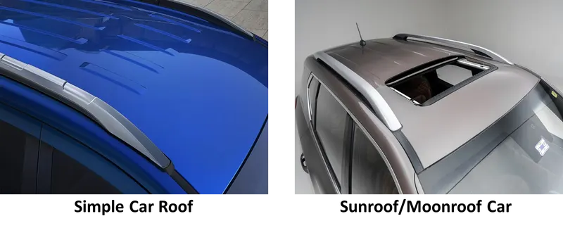
An automobile roof or car top is the portion of an automobile that sits above the passenger compartment, protecting the vehicle occupants from sun, wind, rain, and other external elements. Roof Panel is attached to the car with the help of Front and Rear roof rail, few bow roof is also used to support the roof and increase its strength.
DESIGN CONSIDERATION-
1.Visibility criteria
2.Head clearance
3.Curvature study
4.Hear distortion and snow load criteria
5.Draft analysis
COMPONENET OF ROOF:-
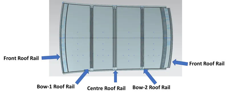
FRONT ROOF RAIL (FRR):-
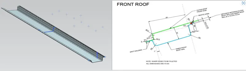
The front roof rail is located on the front of the roof where the wind shield joins with the roof. The visibility criteria and the head room clearance of the passenger are taken into consideration for the bottom flange. One end of the rail is joined using spot welding while the other end is joined with the roof using mastic sealants for increased strength.
BOW-1 ROOF RAIL (1ST BRR):-
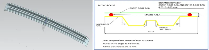
Bow roof is an additional stiffening member for the roof to increase the strength and so that it can satisfy the norms. Both the ends are joined together using mastic sealants to increase strength and also since this would not affect the styling of the roof.
CENTER ROOF RAIL (CRR):-
Centre Roof rail or the reinforcement center is located at the center of the roof . The cross section of this is more since it needs to provide more strength to the roof. Here both are ends are joined together using mastic sealants.
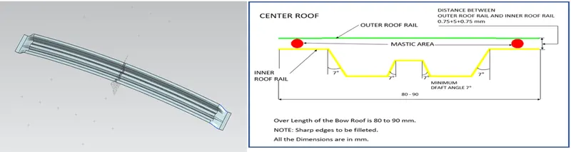
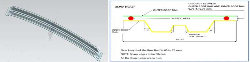
BOW-1 ROOF RAIL (1ST BRR):-
Bow roof-2 is an also additional stiffening member for the roof to increase the strength and so that it can satisfy the norms. Both the ends are joined together using mastic sealants to increase strength and also since this would not affect the styling of the roof.
REAR ROOF RAIL (RRR):-
This roof rail joins with the back door and the roof. Inputs from the backdoor are taken into consideration for designing this roof rail.
Here one end is joined using spot welding while the other end is joined using mastic sealants.
Mastic points & Seals:-
Overall Roof stiffness is derived from the inner and outer panels and their local reinforcements. Considering the roof alone, the inner panel contributes most to the stiffness from its section properties. Both the outer and the inner panels are joined together with the help of the Spot welding and airtight glue is applied at the mastic points as shown in the picture
Mastic Seals place b/w Inner and outer panel to reduce Noise, vibration, and harshness. Every Mastic will have an effect of 80mm Dia. locally. shown in the fig . Inner and outer panel gap is 3 to 5mm.
Analysis:- Heat Distortion curvature study:-
This study is used to find out and predict the heat distortion temperature at where the material starts to soften when exposed to a fixed load. So in order to avoid bending or damage of the roof based on this calculation we will decide the position on the roof bows on the roof.
Formula-
W = [1.73 x 10^(-3) x L] + [1.85 x 10^(-8) x (R^2)/t] + [ 1.10x10^(-3) x l] - 2.68
Where,
L = Roof Length in X-Direction[mm](Roof dimension in 0-Y)
R = Roof curvature
R = 2(Rx*Ry)/(Rx+Ry)
Rx = X curvature
Ry = Y curvature
t = Roof plate thickness [mm]
l = Bow Roof Span [mm]
Judgement Condition : OK< 2.7> 3.1

We predict the analysis results is not satisfy the conditions at two locations, Hence we required emboss on Outer panel of roof for increase the stiffness.
Analysis:- Snow Load curvature study:-
Formula-
Qr =[Iy x t2] / [α x s x [(Rx + Ry)/2]2 x 10-8]
Note: The Qr value given over here is correct. There was a typo error in the formula given in the video.
Where
α = My x Lx2 x 10-12 , My = Y(Ly-Y)
t = Roof plate thickness [mm]
Ly = Distance between the front and rear roof Rails on the Vehicle along with 0Y[mm]
Length of Roof panel with the center point between Roof rail Front /Rear as the reference point of the front and the rear.
Lx= Distance between the Left and Right end of the roof on the Roof BOW [mm]
Width of the roof panel exposed on the surface.
Y = Distance front Roof Rail to Roof BOW[mm]
s= Distance for which Roof BOW bears divided load [mm]
s = L1/2 + L2/2
Iy = Geometrical moment of inertia of Roof BOW (Y cross-section )[mm4]
Rx = Lateral direction curvature radius of roof panel Y cross-section on Roof BOW [mm]
Roof panel curvature Radius of the Length Lx in Front view
Ry = Longitudinal Direction curvature radius of the Roof panel X cross-section on Roof BOW [mm]
Judgement condition = Qr ≥ 3.1
250 ≤ s ≤ 380
Moment of inertia:-
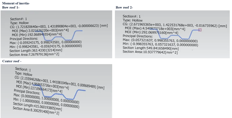

We predict the analysis results is not satisfy the conditions at one points, Hence we required emboss on Outer panel of roof for increase the stiffness
Draft Analysis:-
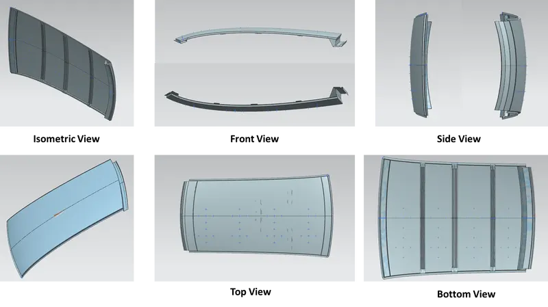
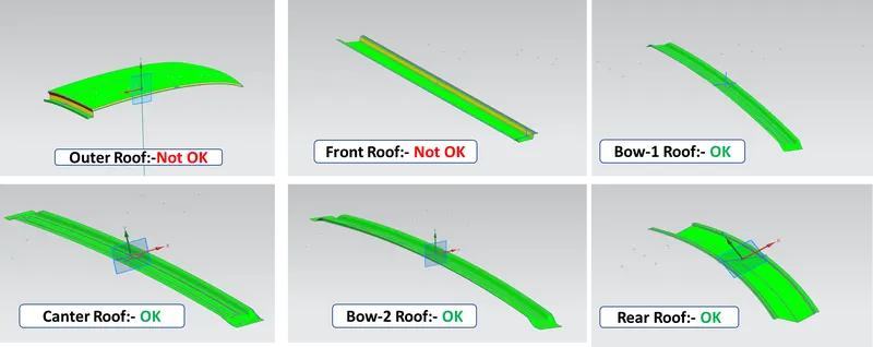
Before we give the part for manufacturing we have to some analysis ourself to check all the constraints and to check if we have any negative draft on a part .
We have a tool called draft analysis in NX Cad to check the following.
When the color is green it means it has a positive draft it means area which are more than 7 degree is shown as green. If it is shown in yellow that means it has less then 7 degrees and if in blue or red then it means it has negative draft.
ROOF CRUSH TEST ANALYSIS:-
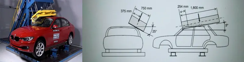
Roof crush test is the design given by the IIHS ( insurance institute of highway safety ) . After analyzing the many accidents IIHS has then fixed some regulations , that how to perform the crush test . IIHS gives the rating based up on this test . For this they consider two points while giving the rating
- How fast the car can reforms to its original shape after the roll over and
- How deep is the protrusion after the roll over
GOAL OF ROOF CRUSH TEST :
To minimize the protrusion into the occupant compartment , so that the seat belts and air bags can do there job in protecting the occupant
CONDITIONS TO FOLLOW FOR ROOF CRUSH TEST :
There are two conditions that should be followed for the roof crush test , they are
1) INITIAL CONDITION :
- Close and lock all the doors
- Close all the windows
2) SECOND CONDITION :
Fix the body sill or chassis frame on a hard lever surface horizontally
METHOD OF APPLYING THE FORCE :
The load is applied in such a way that 50 is tilted from the front end to the rear end and the load will be in 1800 mm in length and 750 mm in width . The load is applied at the position of 250 from the flatness of the roof . The load is applied on the roof for almost 120 sec and the crush speed at which the load applied is 13 mm/sec or less than.
RESULTS :
If the displacements goes above the requirements level then we have to increase the bow roof thickness or add more mastics points to increase the strength . the stronger the roof the better it can protect the occupants in the roll over crashes.
CONCLUSION :
Hence the roof , front roof rail, bow roof rails , central roof rail and the rear roof rail is designed by following the master sections and the moment of inertia , section modulus and draft analysis are carried out to check feasibility manufacturing.