Roof Design
Objective:
The main objective of this project is to develop the car roof design and its reinforcements from the given styling surface. And to prepare a detailed report about the engineering standards for roof design, its design procedure, Draft analysis and manufacturing techniques.
Introduction:
An automobile roof or car top is the portion of an automobile that sits above the passenger compartment, protecting the vehicle occupants from sun, wind, rain, and other external elements. Because the earliest automobiles were designed in an era of horse-drawn carriages, early automobile roofs used similar materials and designs.
Types of Roofs:
1) Hardtops:
When we talk about hardtops, we are referring to the common rigid forms of automobile roofs which we see around. In modern-day cars, this type of roof is made from metal or plastic.
So, the common Toyota Corolla, Camry, and many of the cars in Nigeria are all Hardtops. However, we should say that there are different types. The one we just described is the fixed hardtop. Other types include:
- The detachable hardtops
- The retractable hardtops
2) Sunroof:
This type of roof is also quite popular. You might have been seeing it around. A sunroof is an operable type of roof that allows for an opening in the roof of an automobile; say a window in a roof. It can allow either light or air or both to enter the vehicle. They are either operated manually or automatically. There are 3 popular types of sunroofs. They include:
a. Pop-up:
The pop-up sunroof usually tilts when you open it. It is the most basic and relatively cheaper type of sunroof. Some can even be removed so that they are kept properly, maybe in the trunk whenever you want to go ‘sunroof mode.’
b. Spoiler:
Wait, this is not spoiling anything o. It just means that it can slide. So, the spoiler is a pop-up that would slide, instead of tilting upwards. The advantage of this is that it can easily be restored to its original position by sliding.
c. Panoramic sunroof:
Please take the pronunciation easy. Panoramic sunroofs are distinct. While other sunroofs basically allow air and light or both into the front seats, the panoramic sunroof would allow for both the front and rear.
3) Convertibles:
convertibles are passenger cars that can be driven with or without the entire roof in place. They were first introduced as open-air vehicles; no roofs, no sides. There are different types of convertibles based on the method of conversion and the materials used.
a. Retractable hardtops:
Made from metal or plastic and is retracted automatically.
b. Detachable hardtops:
This type of hardtop is manually removed from the roof and then stored usually in the trunk. They are also made from metal or plastic.
c. Soft tops:
This type of convertibles have roofs that are not made from metal or plastic. They are made of textile. The earliest versions of the convertible used canvas for the roofs. More recent models use cloth materials instead. Other materials used now include latex, vinyl, polyvinyl chloride.
4) The T-Top roof:
An ‘almost convertible’ car. Actually it was built this way because the car manufacturers were not sure the government of the day would approve convertibles. So they made a ‘T-shaped bar’ from front to rear and made the roof on either side detachable. Of course, this type of roof is no longer in production.
Design Consideration of Roof:
- Visibility criteria
- Head room clearance
- Bow roof position
- Curvature study
- Heat distortion and Snow load criteria
- Draft analysis
In design point of view, it is hard to create the roof design. Because for designing roof we have to create no of support rails for enough strength to withstand the load. Bow roofs are primarily fixed in flatter region to enhance strength. Front roof and rear roof rails are fixed to the ditch area using spot weld operation. And front, rear bow roof and center roof rails are fixed to roof using mastic sealants. We don’t want so much gap between roof rails and bow roof area. So, we reducing the NVH issues.
According to conditions we have to decide the number of bows which is used for support the roof. Designing the front roof rail, bow roof rails as well as rear roof rail according to the given master section. After completeing design need to calculate the parameters required for heat distortion criteria and cchecking the values of distortion in the roof are within range or not. Also we have to do iteration for the snow load condition to check the strenth of the roof.
Design Parameters:
The styling surface of a hardtop roof is given by the styling team to develop it. The car roof consists of outer panel and its reinforcements. Those reinforcements are as per below:
- Front Roof Rail
- Bow Roof
- Centre Roof and
- Rear Roof Rail
There are certain engineering standards to design the Automobile Roof. These standards are derived from trial and error method to reduce the material wastage, production cost and to improve the safety over the years. These standards may vary region to region according to the conditions, usage, rules and regulations of that particular region. The common considerations for roof design are head room clearance, driving vision, heat distortion criteria and snow load criteria. The common standards for car roof design are the draft angle should be minimum of 7° and the blends should be minimum of 3+t (t-thickness of the sheet).
Master Section:
Master sections are the crosssection of 3D model. These master sections are widely used in OEMs and in automotive industries to convey the functional requirements of commodity to the design engineer. It gives the parameters like length, width, height, radius and clearance should be considered while designing the particular part or component.
1) Roof outer panel & front roof rail master section:
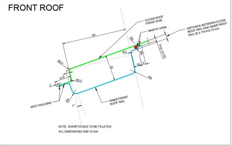
In the above master section the verticle flange is given at 7° followed by the given class A curvature surface. And the distance between the outer roof panel and inner front roof rail is given 32mm. Also the front side the ditch area is given 21.50mm in the outer roof and for the inner front roof rail it is reduced by 2.00mm here at this end there is Spot welding is shown so, there is no any gap between the outer roof and inner front roof rail. Also the blend of the corner dimensions are given at diiferent edges. In the end of the inner front roof rail the 10.00mm and 5.00mm distance horizontal flange are given where the MASTIC Sealant is used. So Area is given for mastic joint is 3.00mm and 5.00mm.
The front roof rail is used as the reinforcement to the roof surface to increase the strength and also used to mount the brackets for some features such as room lamp or map lamp and rear mirror. The depth of the front roof rail is decided based on the visibility criteria line decided for the driver visibility. The width of the front roof rail is decided in such a way that there should be enough headroom clearance between the head of the driver and the end surface of the roof rail to avoid injuries to the person.
2) Bow roof master section:
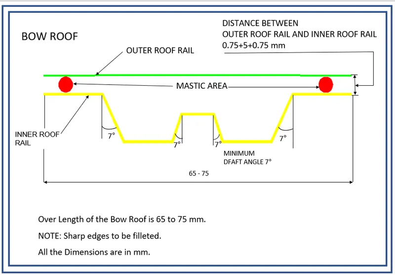
Here, the overall width of the bow roof should lie between 65-75mm and all the embosses have atleast 7° of positive draft with respect to the tooling direction. Then the offset of bow roof outer flange is 0.75+5+0.75mm from the roof outer panel because of the Mastic Area.
3) Center roof master section:
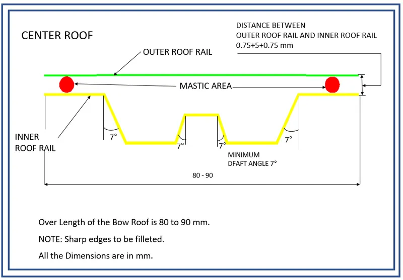
Same as the bow roof, the overall width of the center roof should lie between 80-90mm and all the embosses have atleast 7° of positive draft with respect to the tooling direction. Then the offset of center roof outer flange is 0.75+5+0.75mm from the roof outer panel because of the Mastic Area.
4) Rear roof rail master section:
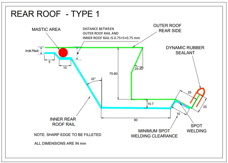
The outer roof panel rear flange should have the negative flange of 25° - 30° draft to accommodate the clearance for back door movements. The overall hight of the rear flange must lie between 70-80mm. The Dimenstions for rear roof rail are offset of (3+0.75+0.75) & (0.75+5+0.75) for front flanges, which is given because of Mastic Area. and the 10.7mm for the offset of center emboss and its width is 90mm. Then the draft angle for emboss connecting the front flange is 32°. Here in the rear area of the rear roof rail is SPOT welded to the outer roof so there is no gap maintain between them at this area.
Design procedure:
For designing this roof we first have to create the assembly file and adding the given styling surface first and by using this different roof rails is created as the separete part. The Roof rail which we must to create is as per below.
- Roof Outer Panel
- Front Roof Rail
- Bow Roof-1
- Center Roof Rail
- Bow Roof-2
- Rear Roof Rail
Here, I have make the hardtop type of roof from the given master section so I am not adding any reinforcement for the central roof rail. Also adding the flanges to all sides of the roof for spot welding of the front roof rail, central roof rail, rear roof rail, and bows.
The thickness of the roof is given 0.75mm.
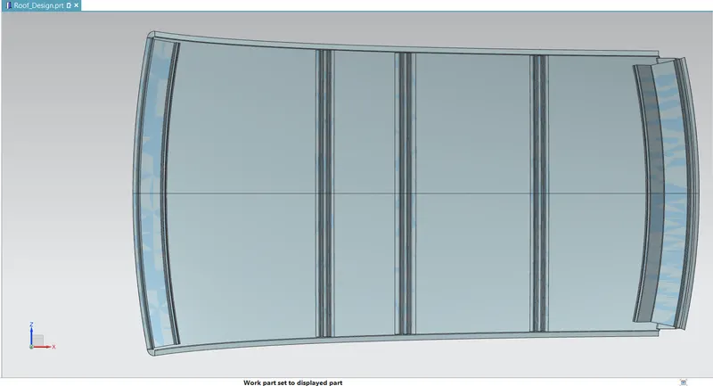
1) Roof Outer Panel :
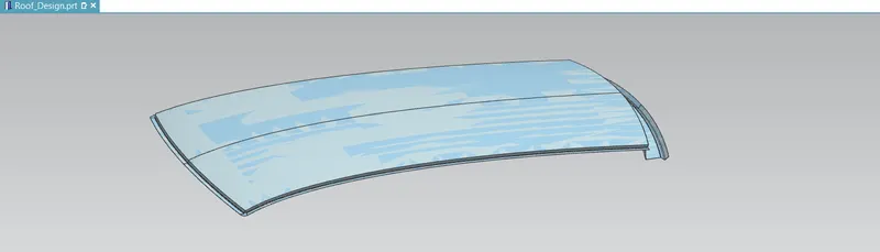
The roof outer panel is the aesthetic part of the roof and also it is the external part which covers the occupant or passenger compartment from the wind shield to the back door.
First of all Importing the The given styling surface and after that half of the portion of styling surface is extracted because the remaining one is the mirror of it. Now unntrimming this extracted surface to fill the gaps and holes and then trim it to remove the extra surface over boundries of styling surface.
Using law extension tool create the flanges as per the given master section from front roof rail as well as rear roof rail. After all flanges are done using edge blend tool the sharp edges is to be removed. Same as the ditch area is also created using the same law extension.
Also the sheet is extended to the Y axis and trimed with the xz plane so gap is removed and after that using mirror geomatery the whole surface is mirror and then using sew it is joined. Then the thickness of the 0.75mm is given to the surface by using the thicken
command.
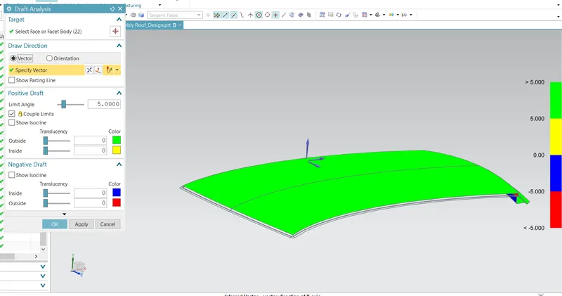
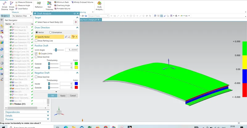
Draft Analysis:
Draft Analysis of the Outer Roof Panel is done which is as per the below image.
2) Front Roof Rail :
The different view for the Front roof rail is given as per the below image
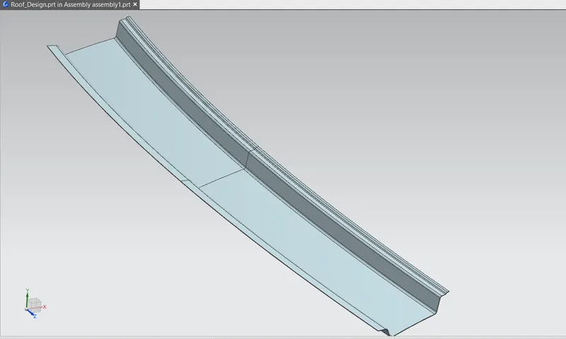
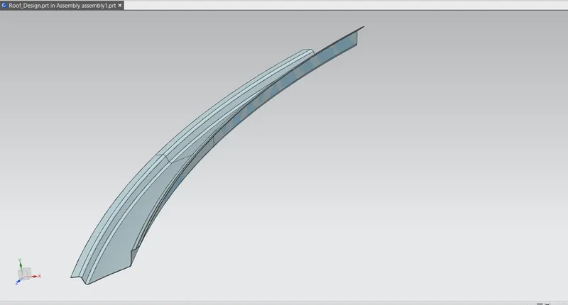
The reference surfaces for front roof are taken from the roof outer panel using the wave geometry linker command. By offsetting this surface as per the given master section we can create the reguired flanges. And by using law extension the verticle surface is created at the draft angle. by trim or corner we can remove the extra surface . after all surface is done as per master section using blend command the sharp edge is to be blended.
Using the sheet extend the whole surface is extended in the y direction and trim it using xz plane and then mirror whole surface and using sew the surface is to be join. After that using thiken command the whole surface is getting the thickness of 0.75mm. We can create the emboss in this surface by using emboss command.
Draft Analysis:
Draft Analysis of the Front Roof rail is done which is as per the below image.
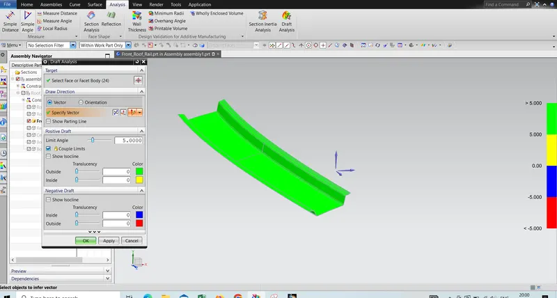
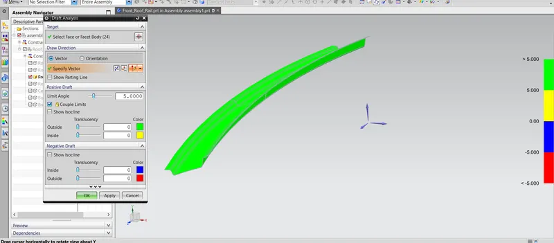
3) Bow Roof - 1:
The different view for the Bow roof 1 is given as per the below image.
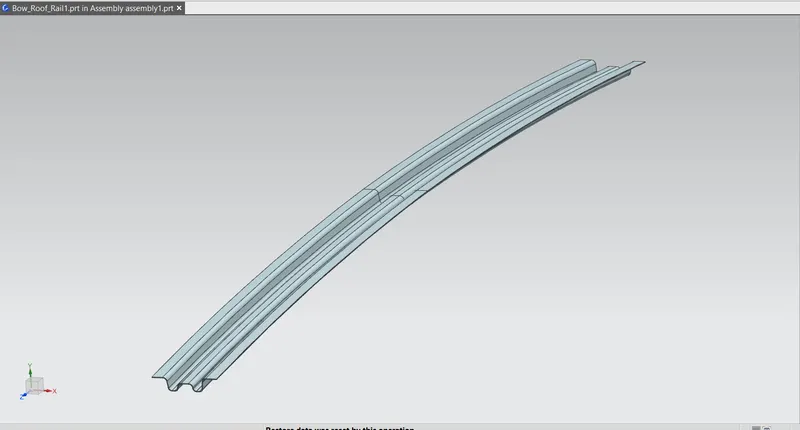
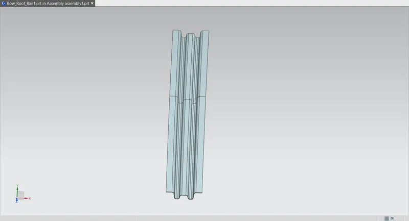
The reference surfaces for bow roof are taken from the roof outer panel using the wave geometry linker command. With help of these surfaces, the bow roof creation starts by offsetting it to the required dimensions according to bow roof master section. After the offsets, using the ‘offset curve in face’ command, required curve was offset to the required positions to remove the unwanted surfaces. and then mirror the whole surface and using the sew command it is joined together. And using thiken given the 0.75mm thickness.
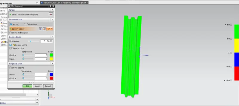
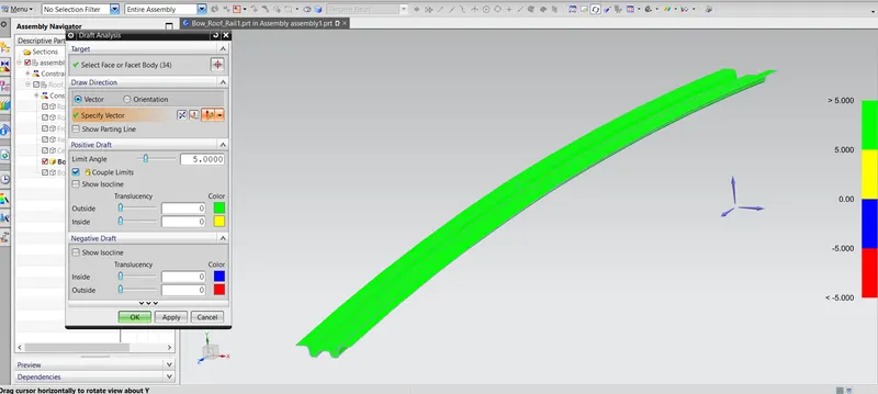
Draft Analysis:
Draft Analysis of the Bow Roof -1 is done which is as per the below image.
4) Center Roof Rail :
The different view for the center roof rail is given as per the below image.
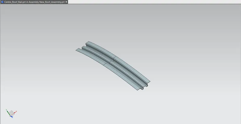
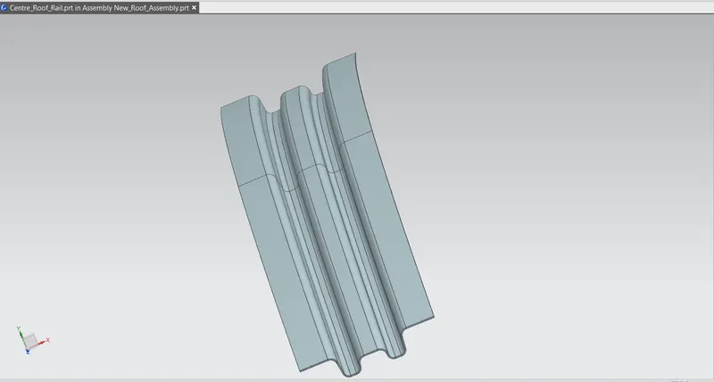
The reference surfaces for bow roof are taken from the roof outer panel using the wave geometry linker command. With help of these surfaces, the center roof creation starts by offsetting it to the required dimensions according to center roof master section. After the offsets, using the ‘offset curve in face’ command, required curve was offset to the required positions to remove the unwanted surfaces. and then mirror the whole surface and using the sew command it is joined together. And using thiken given the 0.75mm thickness.
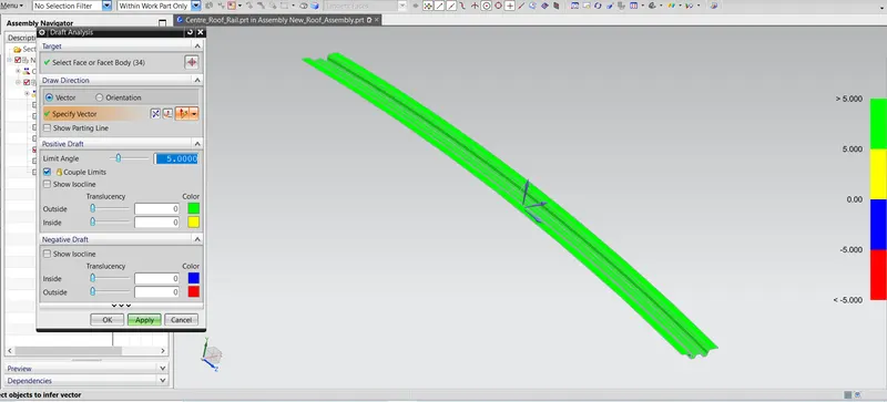
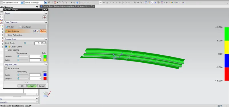
Draft Analysis:
Draft Analysis of the center roof rail is done which is as per the below image.
5) Bow Roof - 2:
The different view for the Bow roof 2 is given as per the below image.
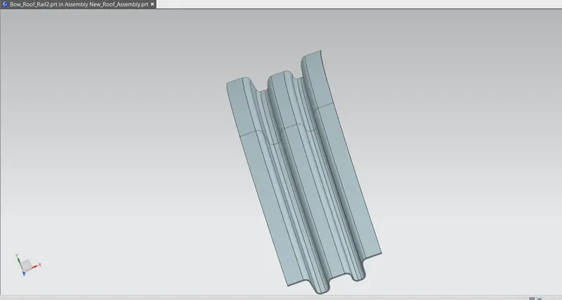
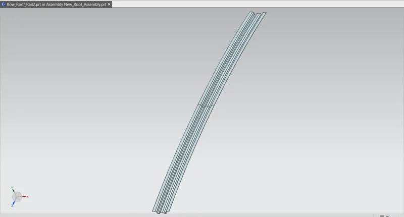
The reference surfaces for bow roof are taken from the roof outer panel using the wave geometry linker command. With help of these surfaces, the bow roof creation starts by offsetting it to the required dimensions according to bow roof master section. After the offsets, using the ‘offset curve in face’ command, required curve was offset to the required positions to remove the unwanted surfaces. and then mirror the whole surface and using the sew command it is joined together. And using thiken given the 0.75mm thickness.
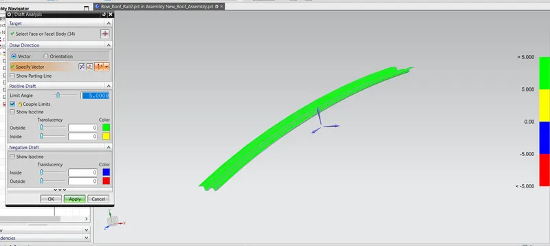
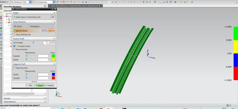
Draft Analysis:
Draft Analysis of the Bow Roof -2 is done which is as per the below image.
6) Rear Roof Rail :
The different view for the Rear Roof Rail is given as per the below image.
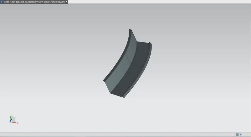
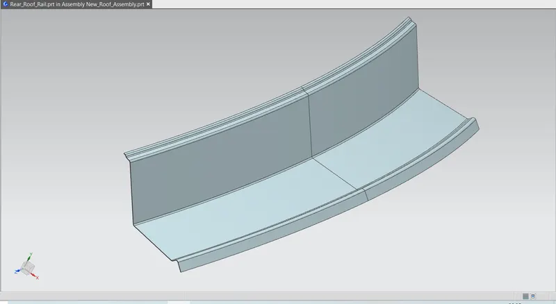
The reference surfaces for Rear roof are taken from the roof outer panel using the wave geometry linker command. With help of these surfaces, the rear roof creation starts by offsetting it to the required dimensions according to rear roof rail master section. After the offsets, using the ‘offset curve in face’ command, required curve was offset to the required positions to remove the unwanted surfaces. and then mirror the whole surface and using the sew command it is joined together. And using thiken given the 0.75mm thickness.
This roof rail joins with the back door and the roof. Inputs from the backdoor are taken into consideration for designing this roof rail. Here one end is joined using spot welding while the other end is joined using mastic sealants.
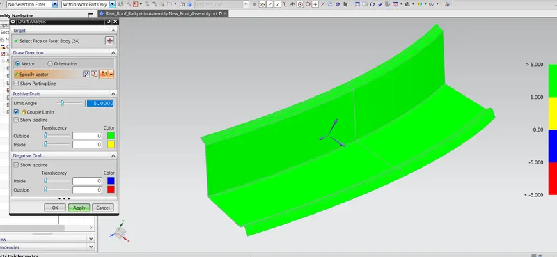
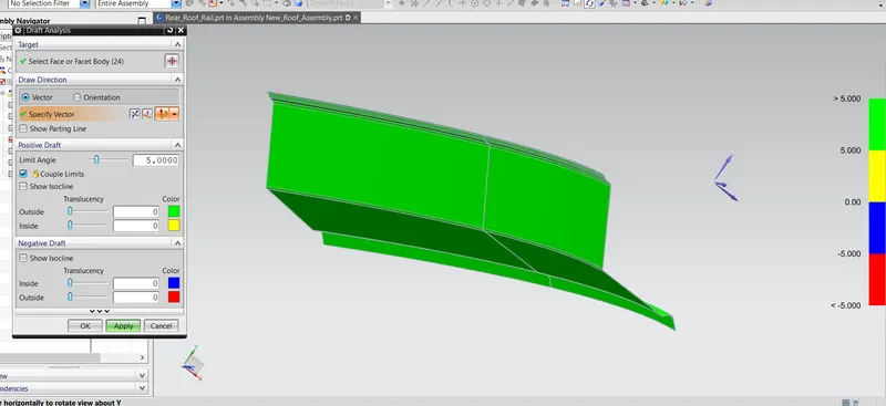
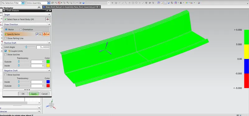
Draft Analysis:
Draft Analysis of the Rear Roof Rail is done which is as per the below image.
Curvature Study on the Roof:
- Heat Distortion calculation
- Snow Load calculation
Heat Distortion:
Heat distortion is temperature limit above which material cannot be used for structural application. This study is useful to find the where the material starts to soften when exposed to a fixed load at elevated temperature. In order to avoid the bending, damage to the roof based on the heat distortion temperature. This study will provide the which position of the bow roof give enough strengthen to roof design.
Bow–Roof Prediction Formula
W = [1.73 x 10^(-3) x L] + [1.85 x 10^(-8) x (R^2)/t] + [ 1.10x10^(-3) x l] - 2.68
Where,
L = Roof Length in X-Direction[mm](Roof dimension in 0-Y)
R = Roof curvature
R = 2(Rx*Ry)/(Rx+Ry)
Rx = X curvature
Ry = Y curvature
t = Roof plate thickness [mm]
l = Bow Roof Span [mm]
Judgment Condition
OK< 2.7
Now from the above equation, for our roof design the parameter is as per below. Here, we have taken the thickness for the sheet for all component is 0.75mm.
So, t = 0.75 mm
for the roof length we have to measure distance of the whole curvature length of the given class A surface where we have to not taken the ditch area. So the roof length is as per below image.
RX & RY (X & Y Curvature):
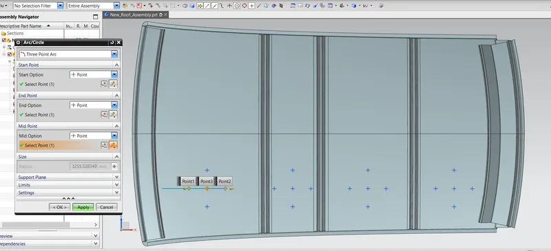
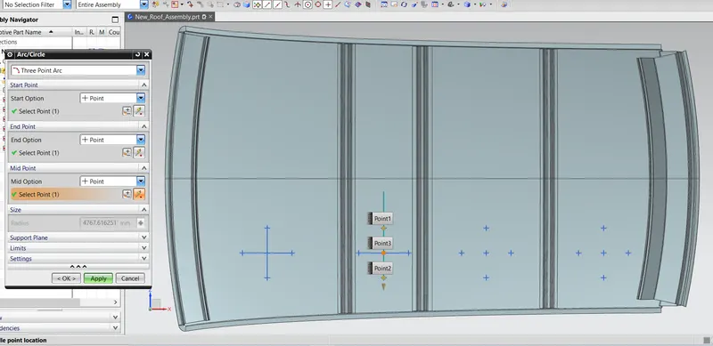
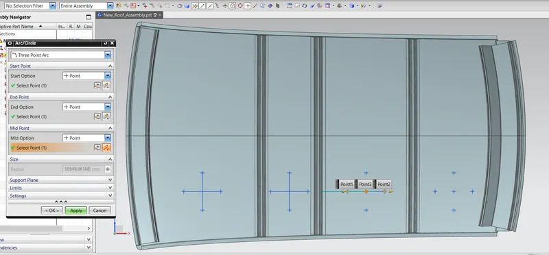
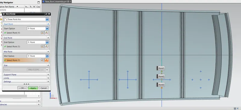
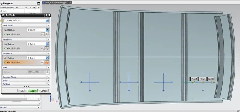
From 0-Y axis, at -3Y axis at distance of 300mm one parallel line is drawn on the perpendicular plane. After that 100mm lines are offset to both side of -3Y line. Now center lines are drawn between each adjacent roof rail edges respectively. and also offsetting this all center line at the 100mm distance on both sides. now, Intersection points are marked on the sketch. Make all geometry lines are reference lines except points. Project the intersection points from sketch to the Roof surface. Join the intersection points on roof surface using the 3D arc curve and measure the radius using measuring tool.
1) RX1 and RY1
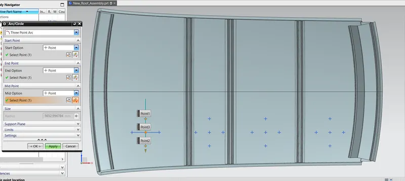
2) RX2 and RY2
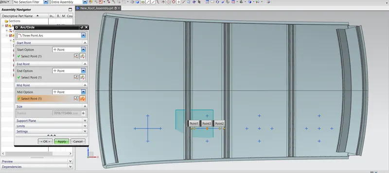
3) RX3 and RY3
4) RX4 and RY4
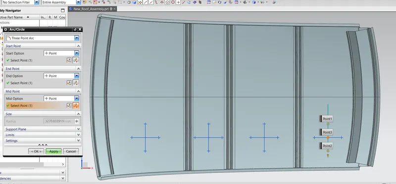
Ly Measurement
for the roof length we have to measure distance of the whole curvature length of the given class A surface where we have to not taken the ditch area. So the roof length is as per below image.
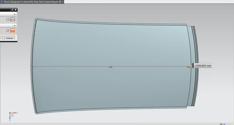
I Measurement
For measuring Bow roof span(I) we have to measure the distance between front roof rail end to the bow roof rail start point and according to it same as in all roof rail. So, the dimensions measurement is shown in below image.
I1
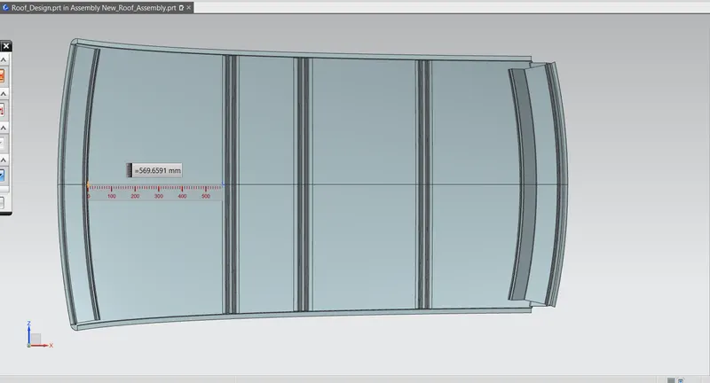
I2
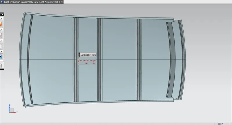
I3
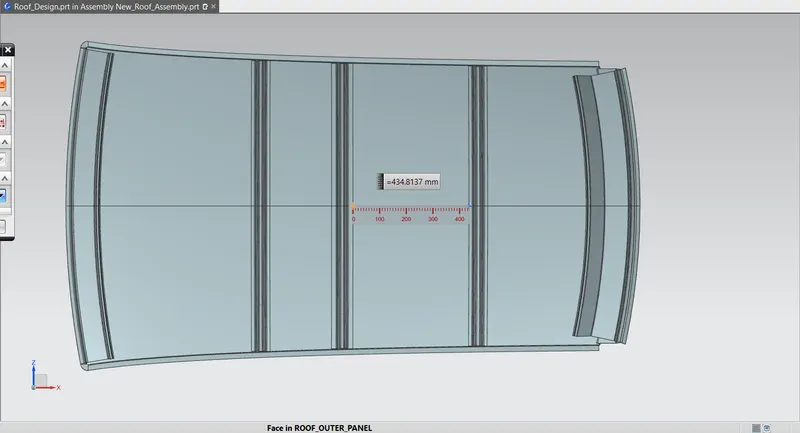
I4
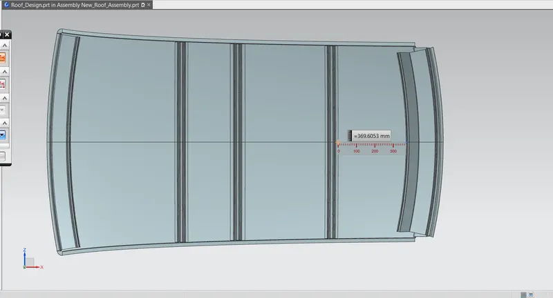
Now, putting the all values in the excel sheet and applying the formula we have got the result as per the below table.

From the above table we conclude that all the values of W< 2.7. which is fullfill the judgement condition. So, that all bow roofs areas are placed at the right place.
Snow Load Criteria:
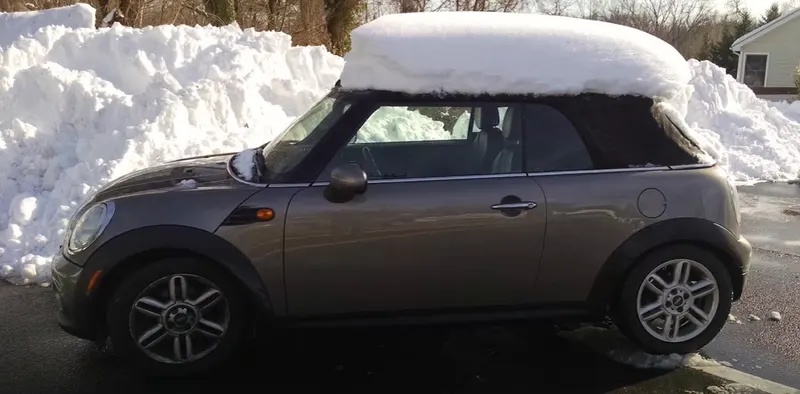
This test is done to know how is the roof behaving when there is a snow over. Normally due to the snow weight the dent will happen. But the roof should be designed in such a way that when the snow is removal the roof should go it its original position. This is the basic requirements for snow load criteria
Qr = [Iy x t2] / [α x s x [(Rx + Ry)/2]2 x 10-8]
Where
α = My x Lx2 x 10-12,
My = Y(Ly-Y)
t = Roof plate thickness [mm]
Ly = Distance between the front and rear roof Rails on the Vehicle along with 0Y[mm]
Length of Roof panel with the centre point between Roof rail Front /Rear as the reference point of the front and the rear.
Lx = Distance between the Left and Right end of the roof on the Roof BOW [mm]
Width of the roof panel exposed on the surface.
Y = Distance Front Roof Rail to Roof BOW [mm]
s = Distance for which Roof BOW bears divided load [mm]
s = L1/2 + L2/2
Iy = Geometrical moment of inertia of Roof BOW (Y cross-section) [mm4]
Rx = Lateral direction curvature radius of roof panel Y cross-section on Roof BOW [mm]
Roof panel curvature Radius of the Length Lx in Front view
Ry = Longitudinal Direction curvature radius of the Roof panel X cross-section on Roof BOW [mm]
Roof panel X curvature radius of length s in Side view
Judgment condition
Qr ≥ 3.1
250 ≤ s ≤ 380
Now from the above equation, for our roof design the parameter is as per below. Here, we have taken the thickness for the sheet for all component is 0.75mm.
So, t = 0.75 mm
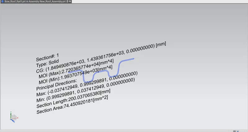
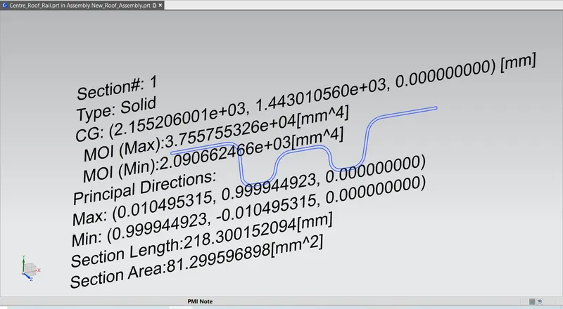
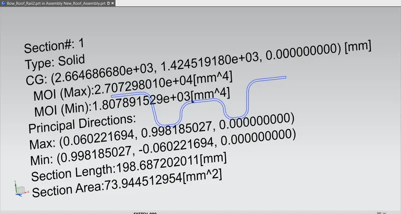
Now, For the measuring the moment of inertia for the bow roof and center roof we have to take the intersection of the part at the verticle center plane and then projecting this curve on the plane and using inertia analysis we can measure the value, here we have to take the MOI(min) for calculation.
Bow Roof-1 moment of inertia:
Center Roof rail moment of inertia:
Bow Roof-2 moment of inertia:
RX & RY (X & Y Curvature):
We have to Draw 100mm lines offset to both side of the of 0Y axis line. Now center lines are drawn between each adjacent roof rail respective. and offsetting this center lines to the 100mm both sides. Intersection points are marked on the sketch. Make all the geometry to the reference lines except points. Project the intersection points from the sketch are projected on the roof surface. Join the project points using 3D arc curve and measure the radius value using measurement tools.
Rx1 & Ry1
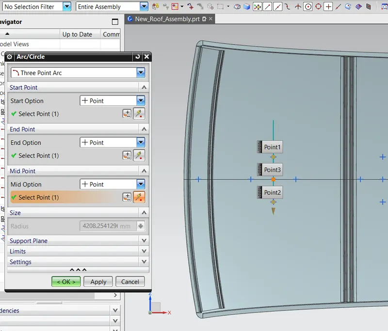
Rx1- 4201.25
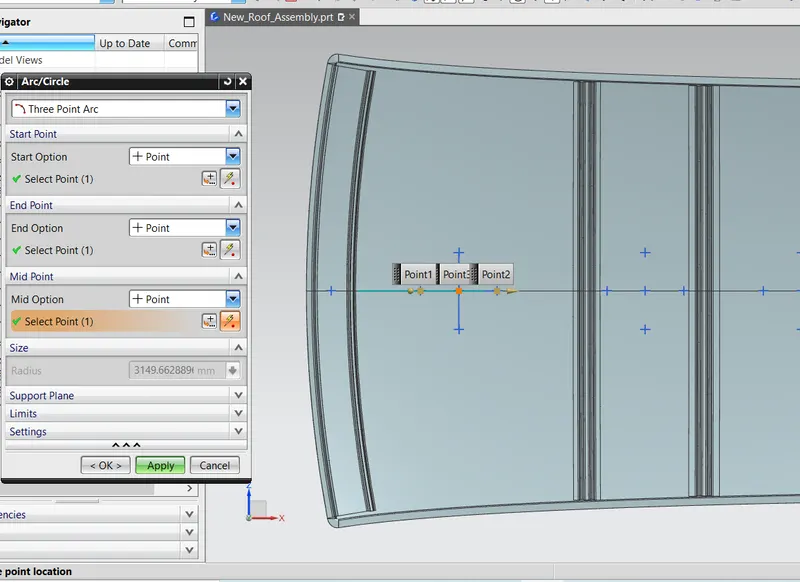
Ry1-3149.66
Rx2 & Ry2
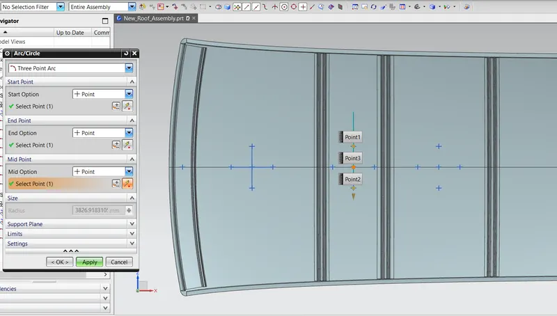
Rx2- 3826.91
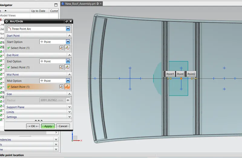
Ry2- 6991.36
Rx3 & Ry3
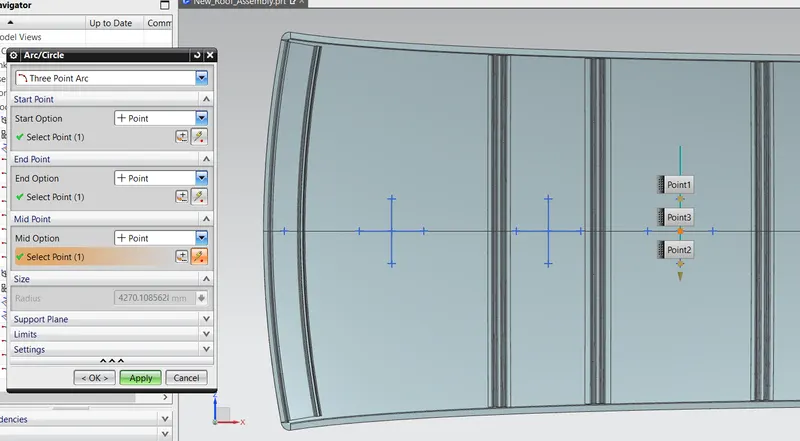
Rx3-4270.10
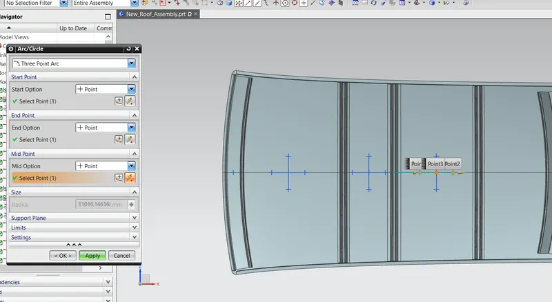
Ry3-11016.14
Calculation of Ly-
For Ly distance we have to measure the distance between the front roof rail center to the rear roof rail center distance. the distance is shown in the below image.
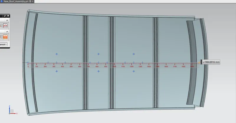
Ly- 1984.89
Calculation of Lx-
For measuring Lx value we have to measure the length of the bow roof rail except the ditch area. the measurement and the values are shown in the below image.
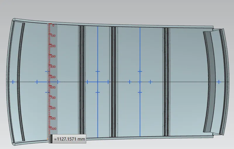
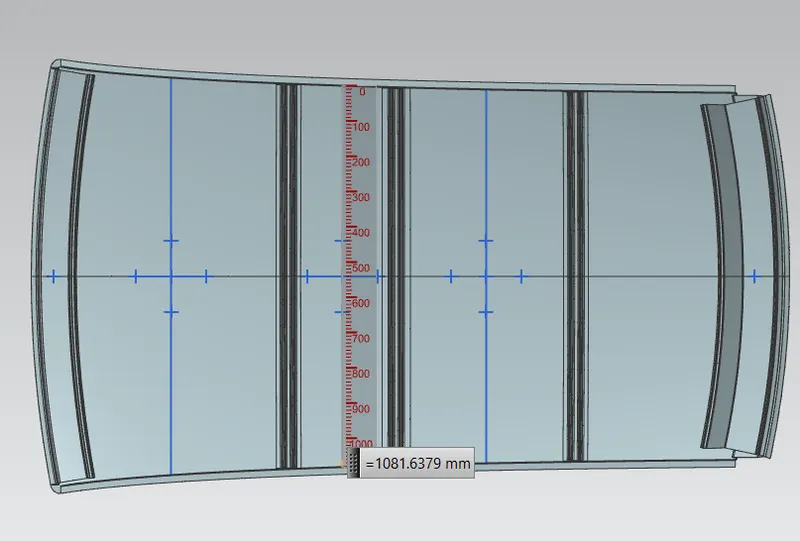
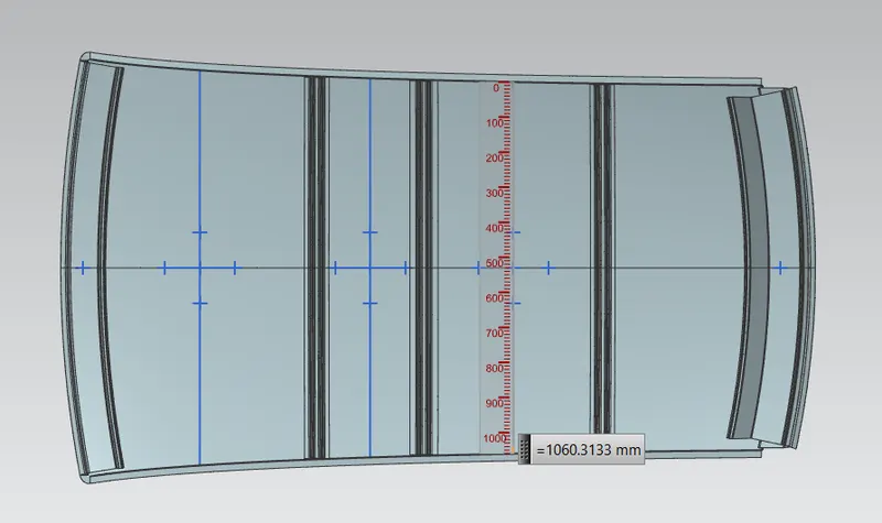
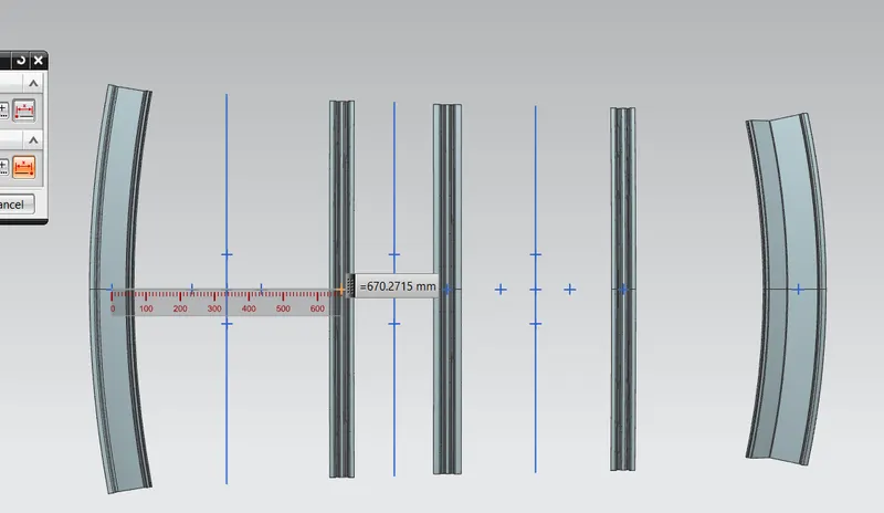
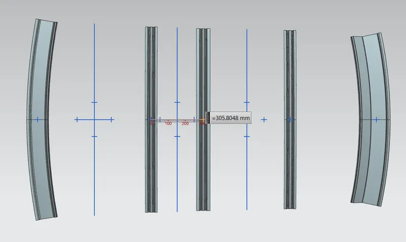
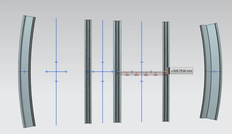
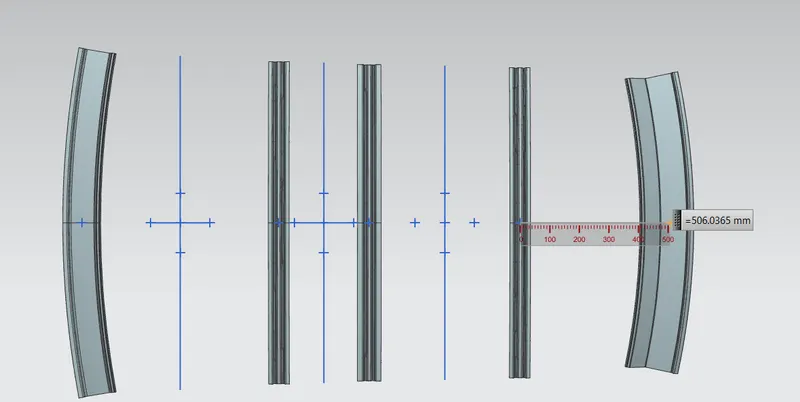
Calculation of L1 and L2
For L1 and L2 we have to take the center distance from front roof rail to the bow roof -1 and bow roof -1 to the center roof rail. and respectively do the same for the other roof rail. the distance shown in the below image.


Conclusion:
- Designed Roof reinforcements such as Front roof rail, Bow roofs, Centre Roof rail, Rear Roof Rail and Ditch area as per given master sections
- Performed Draft analysis for all reinforcements
- Performed Section Inertia Analysis
- Peformed Curvature study and calculated Heat Distortion Criteria & Snow Load criteria
By performing above actions, I learnt and designed Roof reinforcements.
Heat load calculation and snow load criteria calculation completely satisfies the curvature study and the bow roof placements are acceptable.