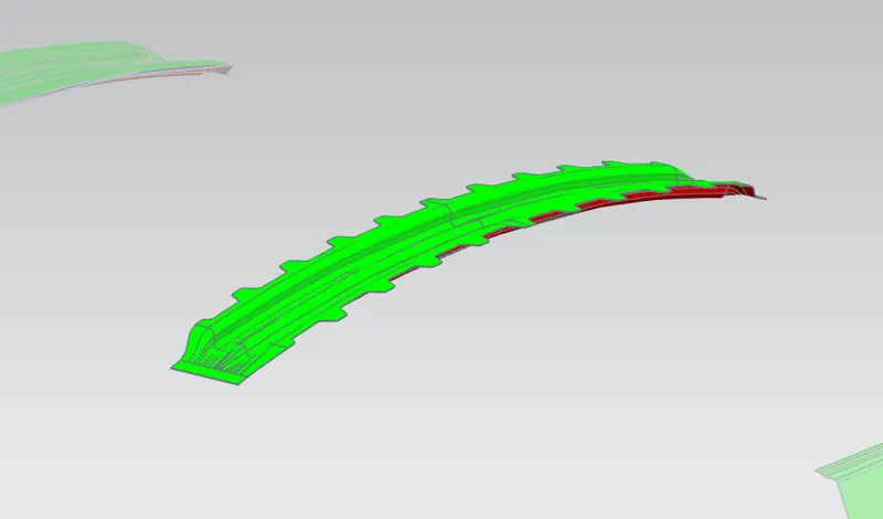
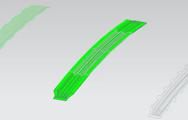
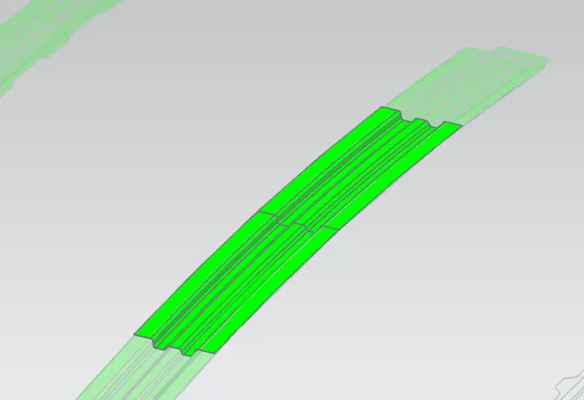
Design of a Car Roof
Objective: Create an Assembly by developing the essential flanges for the outer roof and creating the reinforcements.
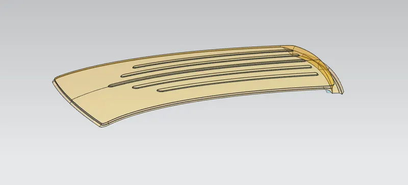
The roof of an Automobile.
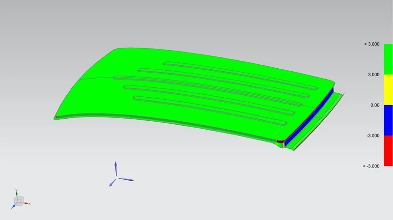
The roof of a car can be defined as the portion of an automobile that covers the passenger area from above, similar to a house roof, protecting the vehicle occupants from sun, wind, rain, and other external elements. Some roofs have a window-like structure on them, known as sunroofs, while convertibles have unique mechanisms that allow the roof to be retracted and stowed away through a wide array of methods depending on the design.
The roof of the car is made up of multiple parts that provide support and strength to the roof component. The actual roof sheet and the roof rails support the roof sheet. There are 3 primary roof rails in a car the front, the center, and the rear, while additional roof rails are called Bow roof rails. The number of bow roof rails depends on the size of the roof. Headroom, visibility criteria, and target region also play a key role in roof design.
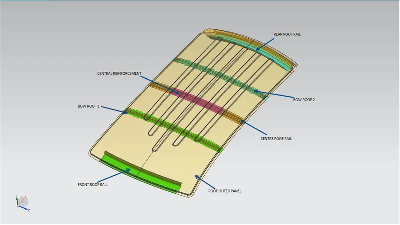
Some important parts of the roof are as follows:
Roof Outer Panel:
The roof is made from a sheet of at least 0.75mm. This protects the cabin from external conditions and objects. The ditch areas are spot welded to the pillars of the car and certain areas of the roof rails, welding on the upper surface is avoided in order to maintain a good aesthetic.
Front Roof Rail:
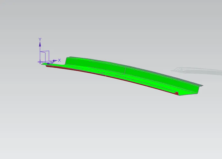
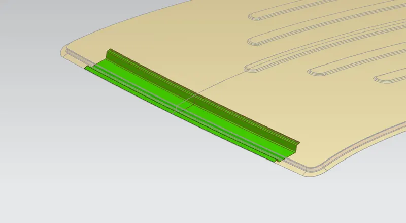
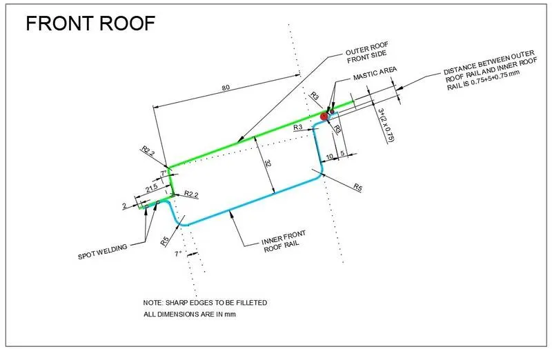
The front roof rail is used to provide strength to the roof panel front and it also acts as a link between windshield glass, roof panel, and headliner (interior trim). The front roof rail is made from a sheet of at least 1.25mm thickness. This part acts as a support for the roof sheet on the front it also provides a mounting area for the windshield. It is designed with support requirements, visibility criteria, and headroom space in mind. The roof is fixed to the roof rails with the use of mastics while the ends are spot welded.
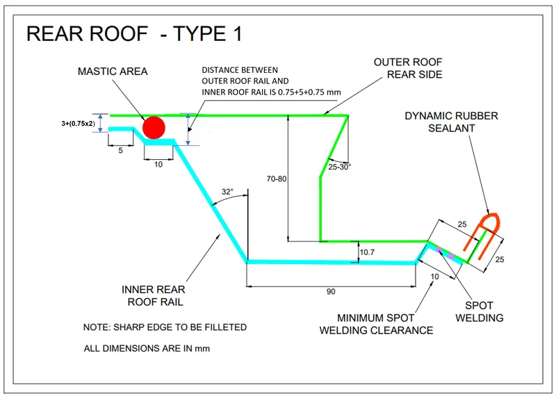
Rear Roof Rail:
The Rear roof rail is used to provide strength to the roof panel front and it also acts as a link between windshield glass, roof panel, and headliner(interior trim).
Bow Roof 1:
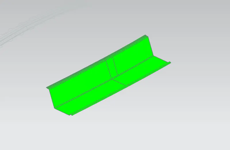
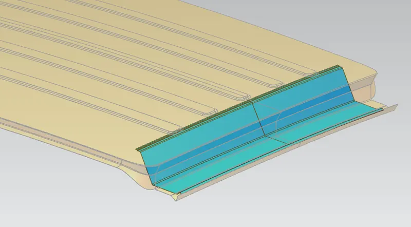
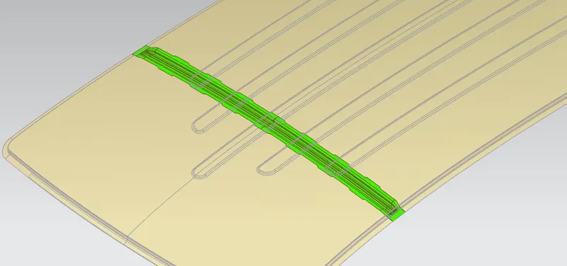
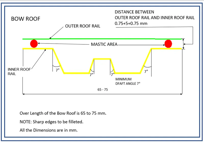
The bow roof rails provide additional support to the roof and are at least 1mm thick, they are positioned in such a way that they provide maximum support to the roof, Care must be taken so that they do not intrude into the headroom requirements of the car. Bow roof rails are an optional feature provided as required by the design. Small cars may have none while large ones may have 3 or more, they may also be integrated into the center roof rail in some cases. The roof is fixed to the roof rails with the use of mastics while the ends are spot welded.
Centre Roof Rail with Reinforcement: (Used when Sun-roof is present)
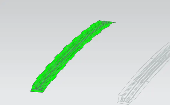
This is the roof rail that runs between the B pillar of the car and provides support to the center of the roof sheet they are usually 1-2mm thick and also provide a support area for the center cabin light mount. The roof is fixed to the roof rails with the use of mastics while the ends are spot welded.
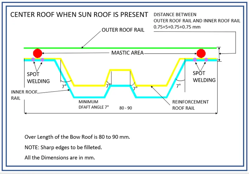
Bow Roof 1:
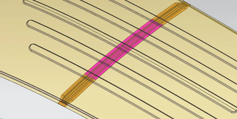
Similar to Bow roof 1, Bow roof 2 is given for additional support to the roof. It is mainly given in a comparatively longer vehicle. You can give as much Bow roof as per the requirements of the OEMs.
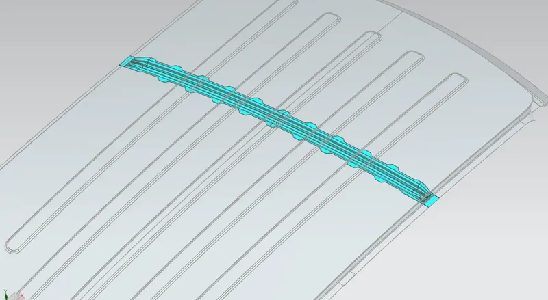
Bow–Roof Prediction:
1. Heat Distortion :
The roof of the vehicle is the most exposed to changes in temperature, these changes cause deformation in the roof. In order to prevent the failure of the roof due to excessive thermal stress, the roof rails must be placed in the correct locations. Improper design of the roof may cause warping, cracking, and failure of mounts.
This calculation is done to find if the roof under thermal stress deforms within set limits.
It is calculated using the formula,
W = (1.73*10^(-3) x L)+(1.85*10^(-8)*(R^2)/t)+(1.10x10^(-3) x l) - 2.68
Where,
L = Roof Length in X-Direction (mm) (Roof dimension in 0-Y)
R = Roof curvature
R = 2(Rx*Ry)/(Rx+Ry)
Rx = X curvature
Ry = Y curvature
t = Roof plate thickness (mm)
l = Bow Roof Span (mm)
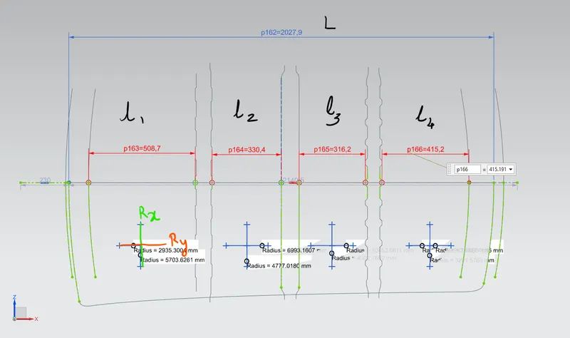
VARIABLES FOR HEAT DISTORTION
The following table shows the Value of W in each section:

Snow Load Prediction:
Snow load is the downward force on a roof by the weight of accumulated snow and ice. The roof or the entire structure can fail if the snow load exceeds the weight the roof was designed to shoulder. Or if the roof was poorly designed or constructed.
It is calculated using the formula,
Qr = (Iy x t2)/(α*s*((Rx+Ry)/2)2 *10-8)
Where,
α = My x Lx2 x 10-12 , My = Y(Ly-Y)
t = Roof plate thickness [mm]
Ly = Distance between the front and rear roof Rails on the Vehicle along with 0Y[mm]
Length of Roof panel with the center point between Roof rail Front /Rear as the front and rear reference point.
Lx = Distance between the Left and Right end of the roof on the Roof BOW [mm]
The width of the roof panel is exposed on the surface.
Y = Distance front Front Roof Rail to Roof BOW[mm]
s = Distance for which Roof BOW bears divided load [mm]
s = L1/2 + L2/2
Iy = Geometrical moment of inertia of Roof BOW (Y cross-section )[mm4]
Rx = Lateral direction curvature radius of roof panel Y cross-section on Roof BOW [mm]
Roof panel curvature Radius of the Length Lx in Front view
Ry = Longitudinal Direction curvature radius of the Roof panel X cross-section on Roof BOW [mm]
Roof panel X curvature radius of length s in Side view
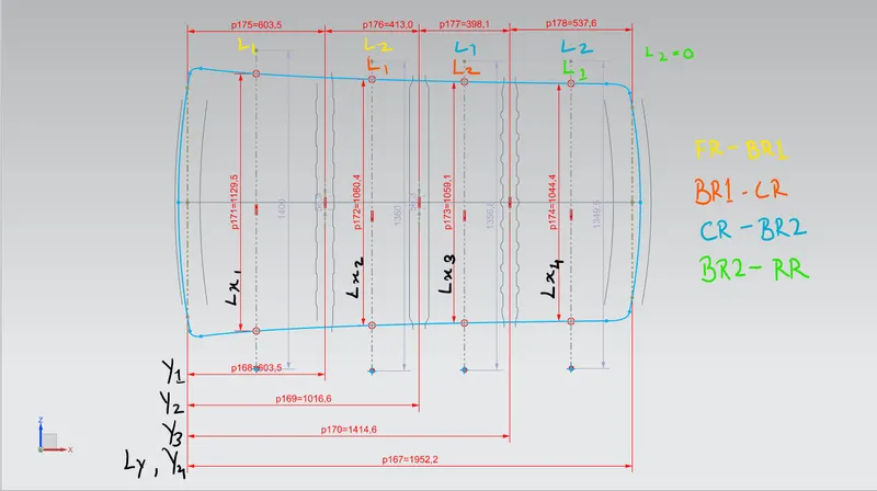
VARIABLES FOR SNOW LOAD
MOI :
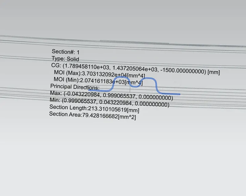
BOW ROOF -1
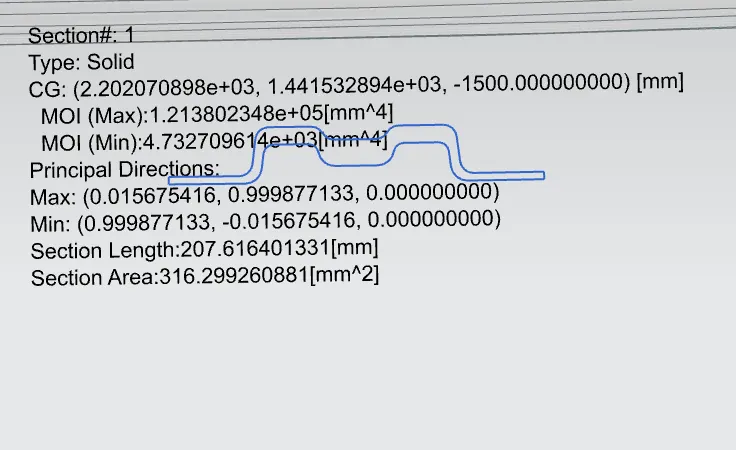
CENTRE ROOF RAIL
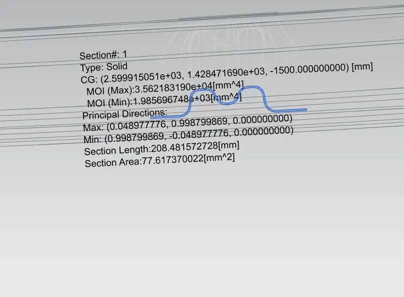
BOW ROOF 2
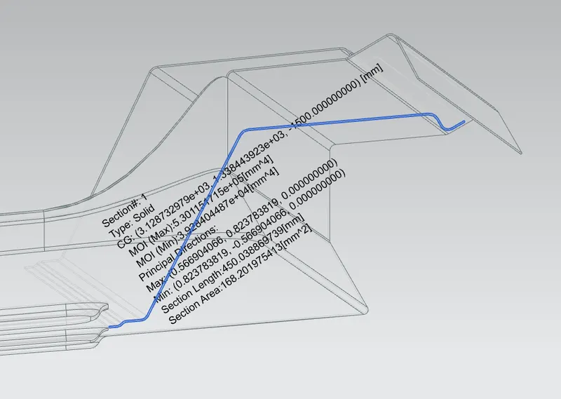
REAR RAIL
The following table shows the Value of Qr in each section:

Draft Analysis of the Parts: