Roof Design
Roof Design
ROOF
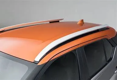
An automobile roof is the portion of an automobile that sits above the passenger compartment, protecting the vehicle occupants from sun, wind, rain, and other external elements. Though it just looks like a styling surface that protects from sun, wind and other elements, various environmental conditions are taken into account for designing of the same. Roof should be provided with proper reinforcements for strengthening. Vehicle roof can be subjected to high heat conditions or load during snowy conditions. To make the roof withstand these conditions, various calculations are done. This ensures the safety of the passengers in the vehicle.
TYPES OF ROOF
- Convertible roofs
- Hardtops
- Sunroofs
- T-tops
- Targa tops
- Vinyl roofs
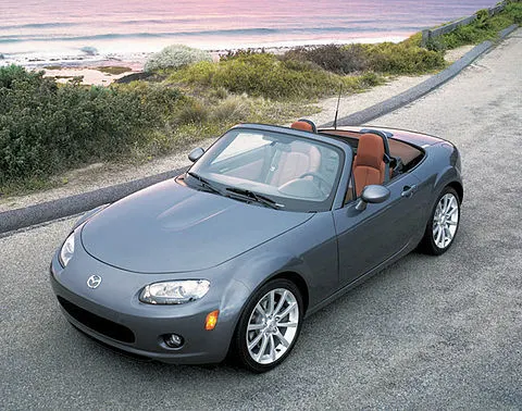
- Convertible roofs ; A convertible or cabriolet is a passenger car that can be driven with or without a roof in place. The methods of retracting and storing the roof vary amoung eras and manufacturers.
- Hardtops
A hardtop is a rigid form of automobile roof, which for modem cars is typically constructed from metal. a hardtop roof can be either fixed, detachable for seperate storing or retractable within the vehicle itself.
- Sunroofs
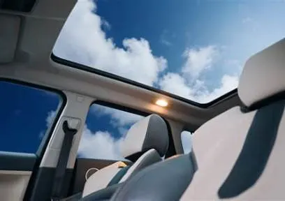
A sunroof is a movable panel that opens to uncover a window in an automobile roof, allowing light and fresh air to enter the passenger compartment. Sunroofs can be manually operated or motor driven, and are available in many shapes, sizes and styles.
- T-top
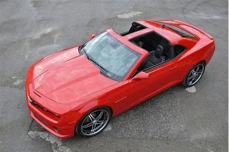
A T-top is an automobile roof with a removable panel on each side of a rigid bar running from the center of one structural bar between pillars to the center of the next structural bar. The panels of a traditional T-top are usually made of auto grade safety glass.
- Targa tops
Targa top, or targa for short, is a semi-convertible car body style with a removable roof section and a full width roll bar behind the seats. The term was first used on the 1966 Porsche 911 Targa, and it remains a registered trademark of PorscheAG.
- Vinyl roof
Vinyl roof refers to a vinyl covering for an automobile's top.
DESIGN CONSIDERATIONS FOR A ROOF
- Visibility criteria
- Head clearance
- Curvature study
- Heat distortion and snow load criteria
- Draft analysis
MASTER SECTION
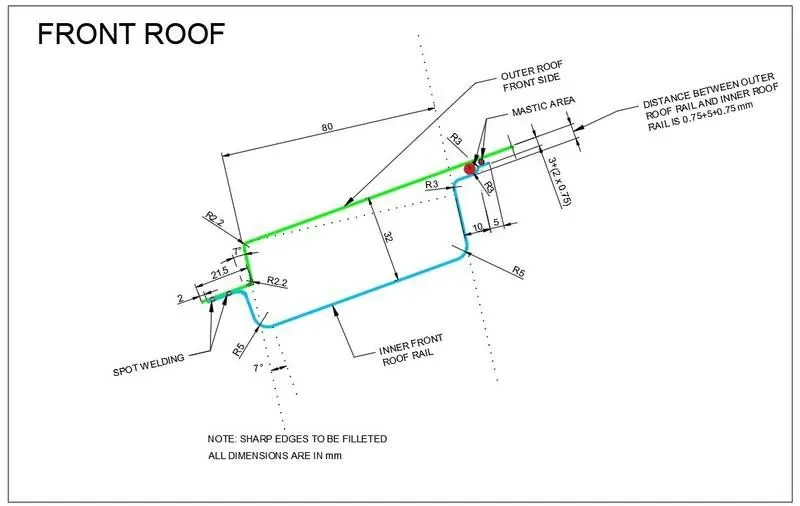
- Front Roof Rail
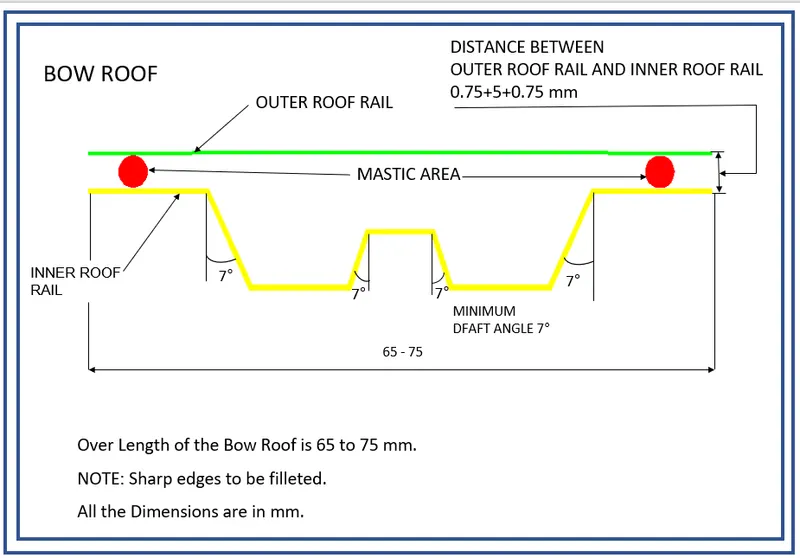
- Bow Roof Rail
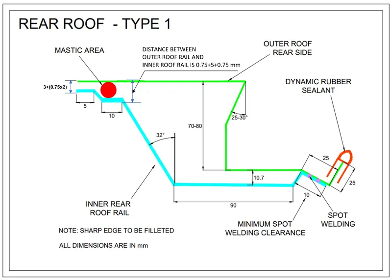
- Rear Roof Rail
COMPONENTS OF ROOF
- Front Roof Rail
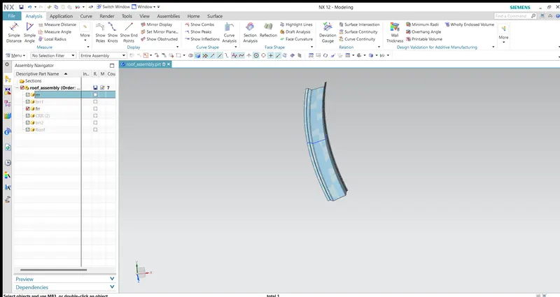
The front roof rail is located on the front of the roof where the wind shield joins with the roof. The visibility criteria and the head room clearance of the passenger are taken into consideration for the bottom flange. One end of the rail is joined using spot welding while the other end is joined with the roof using mastic sealants for increased strength.
- Rear Roof Rail
This roof rail joins with the back door and the roof. Inputs from the backdoor are taken into consideration for designing this roof rail. Here one end is joined using spot welding while the other end is joined using mastic sealants.
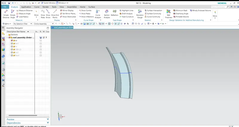
- Centre Roof Rail
Centre Roof rail or the reinforcement centre is located at the centre of the roof . The cross section of this is more since it needs to provide more strength to the roof. Here both are ends are joined together using mastic sealants.
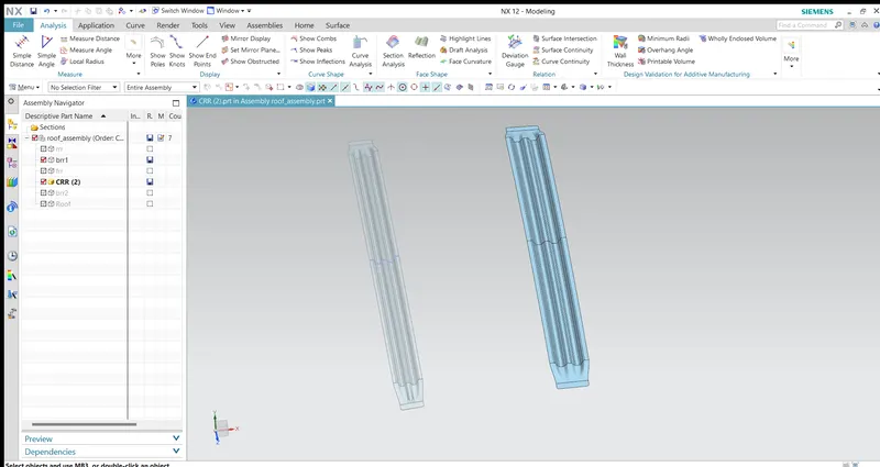
- Bow roof 1
Bow roof is an additional siffening member for the roof to increase the strength and so that it can satisfy the norms. Both the ends are joined together using mastic sealants to increase strenght and also since this would not affect the styling of the roof.
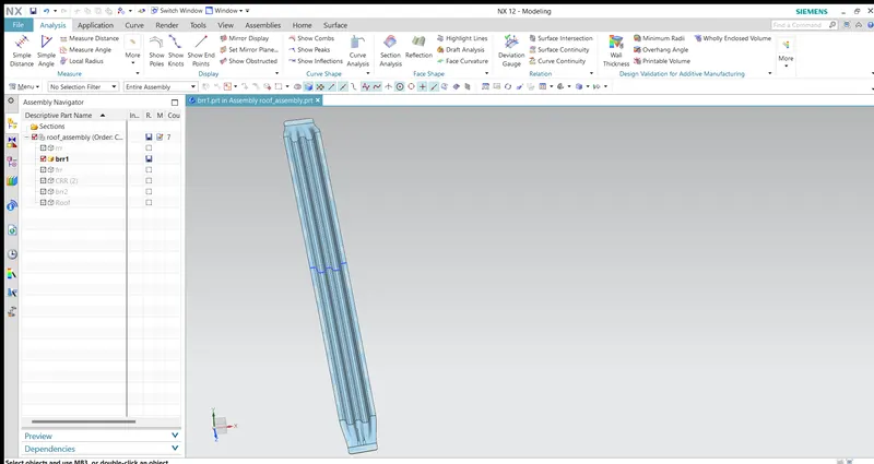
- Bow roof 2
This bow roof also have the same purpose as that of the first one. This one is located between the centre bow roof and rear roof rail.
HEAT DISTORTION CRITERIA:
The heat radiating from the sun causes the roof of the car to change in the metallic regions. The heat distortion study plays a major role in sheet metal usage. heat distortion temperature is a temperature limit above which the material cannot be used for the structural applications. This study is used to predict the heat distortion temperature at where the material starts to soften when exposed to a fixed load at elevated temperature. In order to avoid bending or damages on the roof, based on the heat distortion temperature, this study will predict the bow roof position which helps to strengthen the roof.

Bow–Roof Prediction Formula
W = [1.73 x 10^(-3) x L] + [1.85 x 10^(-8) x (R^2)/t] + [ 1.10x10^(-3) x l] - 2.68
Where,
L = Roof Length in X-Direction[mm](Roof dimension in 0-Y)
R = Roof curvature
R = 2(Rx*Ry)/(Rx+Ry)
Rx = X curvature
Ry = Y curvature
t = Roof plate thickness [mm]
l = Bow Roof Span [mm]
Calculation
- Create a sketch on top roof and drawn a horizontal line at the centre.
- Then offset this line below 300mm and called it as -3Y line.
- From the _3Y line offset 100 mm above and below and convert all these line into reference lines.
- Draw the vertical lines at the middle of the each reinforcements and offset it to 100 mm both sides.
- Intersection point is created where the lines are met.
- Project these points to the outer roof panel.
- Now draw the arc by connecting three points and measure the min radius value.
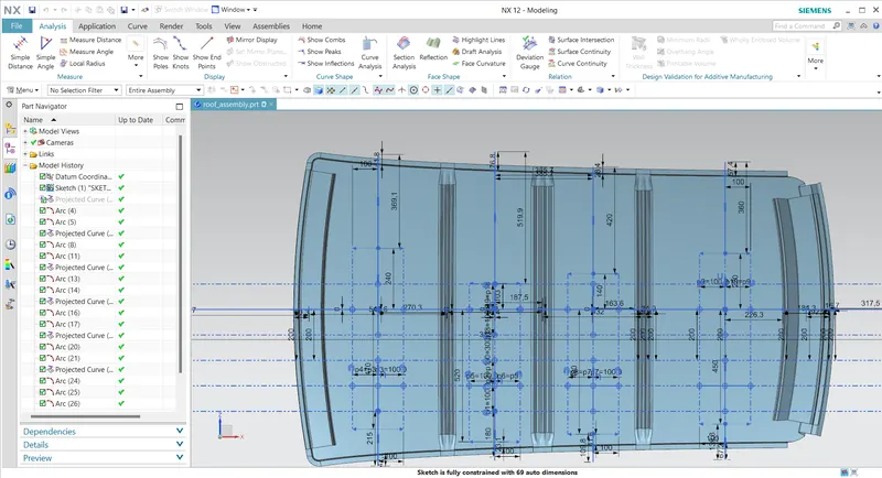
The values are tabulated and 'W' is calculated.
-
Roof Rails Rx (mm) Ry (mm) R (mm) L (mm) I (mm) t (mm) W RESULT FRR - BR1 5731.03 2676.24 3648.65 2182.18 540.55 0.75 1.32 OK BR1 - CRR 4957.44 6257.23 5532.01 2182.18 370.07 0.75 2.24 OK CRR - BR2 4190.42 9528.72 5820.96 2182.18 397.09 0.75 2.35 OK BR2 - RRR 3352.76 14011.95 5410.82 2182.18 636.88 0.75 2.51 OK
SNOW LOAD CRITERIA
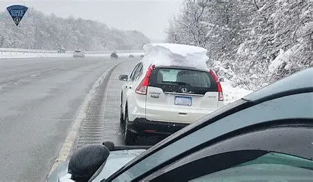
This test is done to know how is the roof behaving when there is a snow over. Normally due to the snow weight the dent will happen. But the roof should be designed in such a way that when the snow is removal the roof should go it its original position. This is the basic requirements for snow load criteria.
Snow Load Prediction Formula
Qr = [Iy x t2] / [α x s x [(Rx + Ry)/2]2 x 10-8]
α = My x Lx2 x 10-12 , My = Y(Ly-Y)
t = Roof plate thickness [mm]
Ly = Distance between the front and rear roof Rails on the Vehicle along with 0Y[mm]
Lx = Distance between the Left and Right end of the roof on the Roof BOW [mm]
Y = Distance front Front Roof Rail to Roof BOW[mm]
s = Distance for which Roof BOW bears divided load [mm]
s = L1/2 + L2/2
Iy = Geometrical moment of inertia of Roof BOW (Y cross-section )[mm4]
Rx = Lateral direction curvature radius of roof panel Y cross-section on Roof BOW [mm]
Ry = Longitudinal Direction curvature radius of the Roof panel X cross-section on Roof BOW [mm]
Calculation
- Create a sketch on top roof and drawn a horizontal line at the centre.
- Offset this line to 100mm on both sides.Convert all these line into reference lines.
- Draw the vertical lines at the middle of the each reinforcements and offset it to 100 mm both sides.
- Intersection point is created where the lines are met.
- Project these points to the outer roof panel.
- Now draw the arc by connecting three points and measure the min radius value.
- and finding the moment of inrtia ofall section .
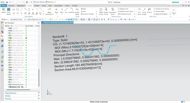
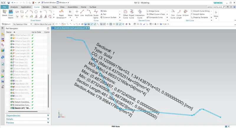
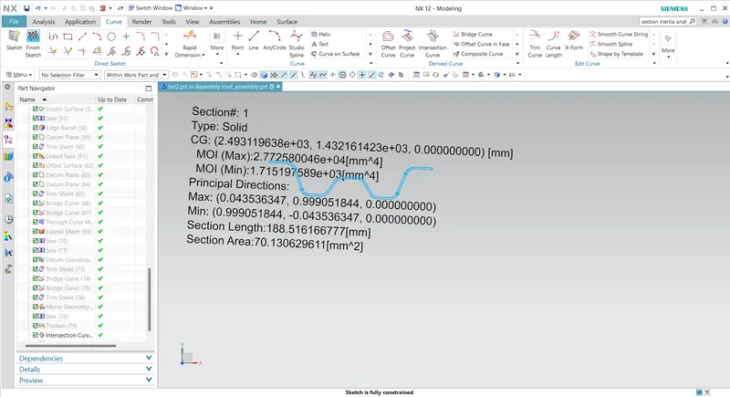
The values are tabulated and 'Qr' is calculated.
| Roof Rails | Iy (mm4) | Lx (mm) | Ly (mm) | Y (mm) | L1 (mm) | L2 (mm) | Rx (mm) | Ry (mm) | t (mm) |
| FRR - BR1 | 4.6653 | 1132.45 | 2182.18 | 540.55 | 540.55 | 375.08 | 4450.25 | 2718.58 | 0.75 |
| BR1 - CRR | 1.7216 | 1086.10 | 2182.18 | 915.63 | 375.08 | 397.10 | 3732.13 | 6170.50 | 0.75 |
| CRR - BR2 | 2.1037 | 1063.26 | 2182.18 | 1312.73 | 397.10 | 636.88 | 4157.90 | 9814.40 | 0.75 |
| BR2 - RRR | 1.7151 | 1045.26 | 2182.18 | 1949.61 | 636.88 | _ | 4133.18 | 15590.80 | 0.75 |
| Roof Rail | My | α | S | Qr | RESULT |
| FRR - BR1 | 887383.09 | 1.138 | 457.81 | 39.20 | Ok |
| BR1 - CRR | 1159691.17 | 1.368 | 386.05 | 7.496 | Ok |
| CRR - BR2 | 1141353.09 | 1.290 | 516.99 | 3.635 | Ok |
DRADT ANALYSIS
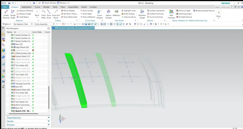
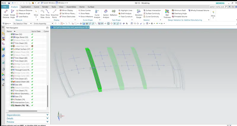
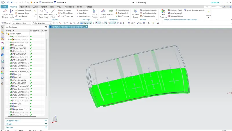
Draft analysis is done after determining the tooling axis, draft analysis is used to check whether the minimum draft (7 degrees) is maintained or not.The minimum draft angle of all the componts in the roof is 7 degrees.
Conclusion:
- Essential roof components such as bow and center rails required with flanges and reinforcements are designed.
- Curvature study on roof was analysied with heat distortion and snow load standards
- Draft analysis was done to check tool ablilty.