Roof Design
Roof design considerations:
- Visibility criteria
- Head room clearance
We have to add Bow roof supports at required places.
Roof Design:
Extracted outer surface of the roof from given model
Since it's profile symmentric with respect to center vertical plane,we splitted into half.
So that it is easy to do the work.
We will create mirrored geometry once all profile creation work completed.Then it will be joined later.
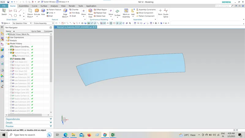
Then using Law extension command & studio surface option created front ,rear & side ditch profile of the roofs.
Dimension & shape of the profile created reffered from given master section.
Using fillet command all sharp edges converted into smooth surface.
Unspecified values assumed by our own to meet final profile as per given in master section.
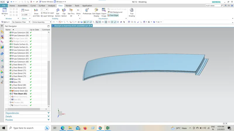
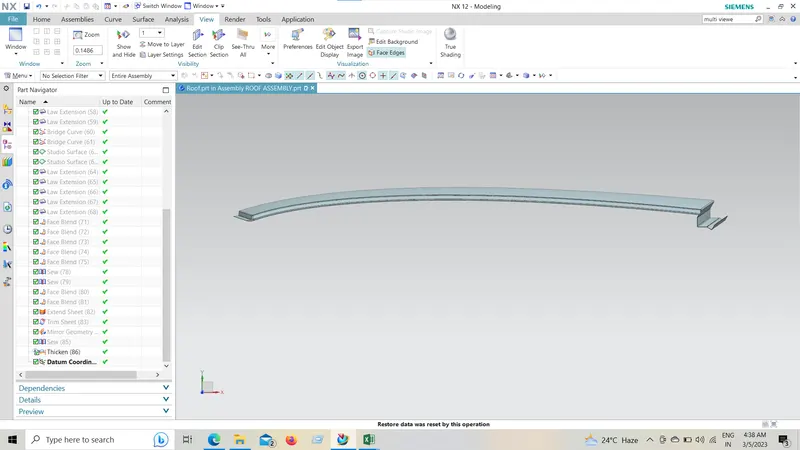
After completion of all features ,it was mirrored & joined using sew command.
Then using Thicken command it was converted into solid part.
We have added 0.75mm thickness as per mentioned in master section.
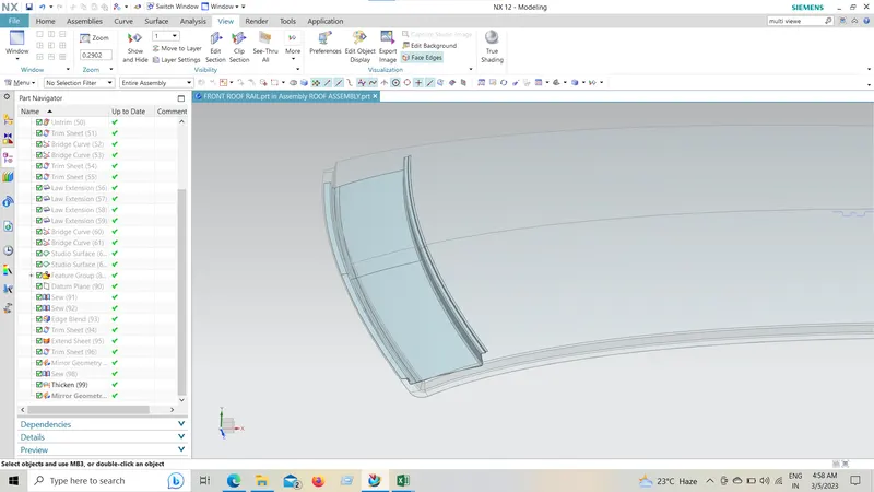
Front roof rail:
The front roof rail is the main support member for roof front end.
Same method as used in outer roof panel was used to create front roof rail.
The clearance between front roof rail & outer panel inner surafce at joining surfaces maintained for spot welding & mastic joints.
We have added 0.75mm thickness to vonvert into solid body.
Draft angle used at all the faces minimum of 7 degree.
Draft angle analysis:
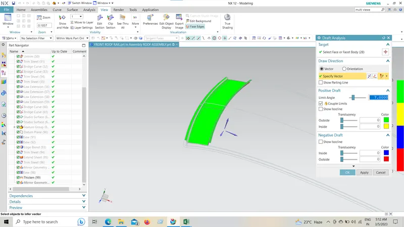
It is verified with draft angle analysis for 7 degree minimum radius value.
Only at particular places we found red regions.But we have created this profile based on given master section.
That's why we did't change that face angle.
Bow roof 1 Design:
Same method as used in front roof rail was used to create bow roof 1.
We have decided to keep the Bow roof support 25% of its total length (From front end).
Bow roof profile created as per given master section.
End of the this rail has been connected with roof outer panel using Through curve mesh command.Bridge curve created before this option for joining surface guide.
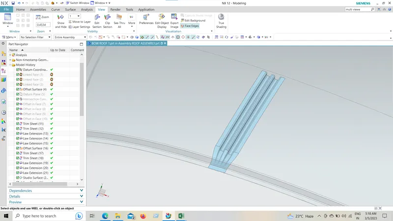
We have added 0.75mm thickness for this part.
Clearance provide for mastic joints.
Mirrored this part with respect to center plane.Then joined using sew command.
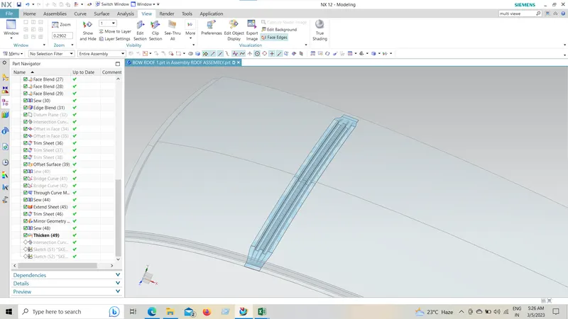
Draft angle analysis:
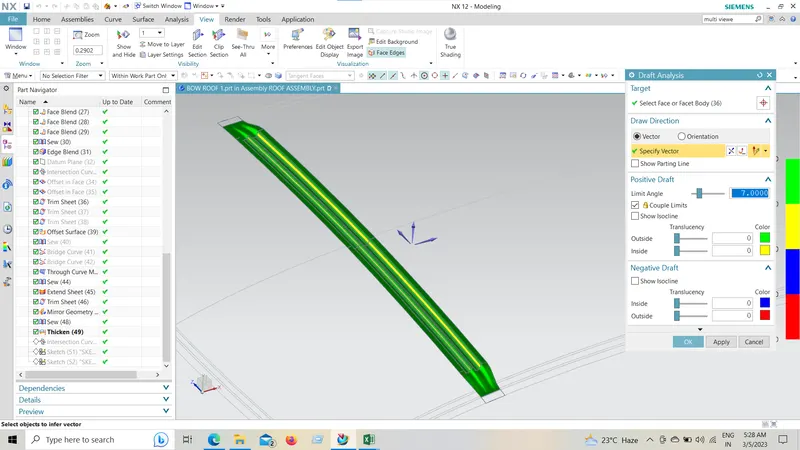
Completly it is showing in green colour.So that it is passed for draft angle analysis for minimum draft angle of 7 degree.
Bow Roof 2:
The same method repeated as we did for bow roof 1.
This is placed 25% of it's total length away from rear end.
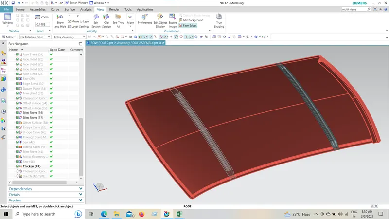
0.75mm thickness added for this part.
Draft angle analysis:
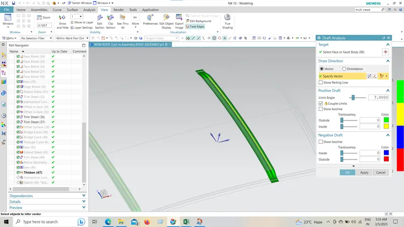
It is passed in draft angle analysis for minimum 7degree angle.
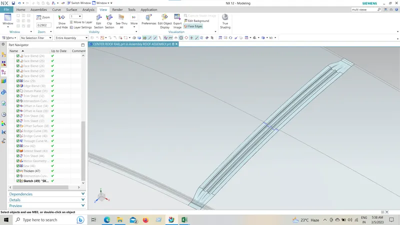
Center roof rail:
This is placed exact center of roof outer panel.
Same steps as used in bow roof rails was repeated here to create this rail
Profile created followed by given master section.
Draft angle analysis:
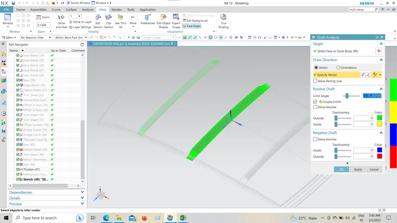
This is also passed in draft angle analysis for 7degree minimum angle.
Rear roof rail:
It is main support for rear side of roof panel.
The profile given in master section followed for this part design.
Undetermined dimensions assumed by our own.It would be suitable to match profile given in master section.
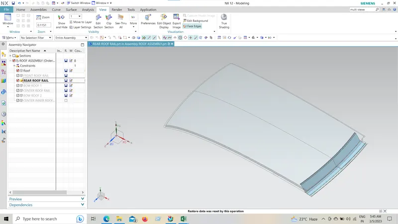
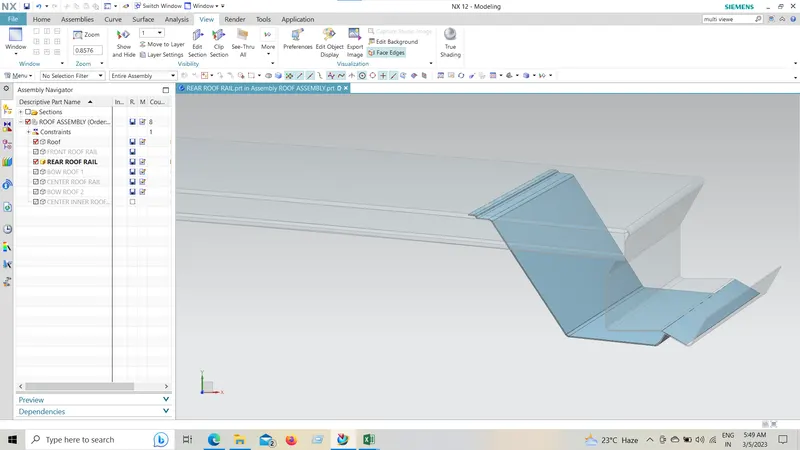
Thickness added for 0.75mm.
Both end of this part trimmed with some particular distance from roof panel edge.
Draft angle analysis:
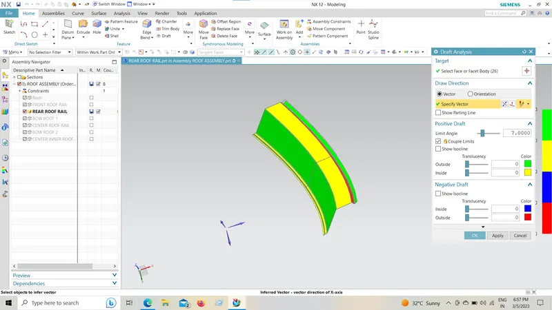
All the support members created & attached with roof outer panel.
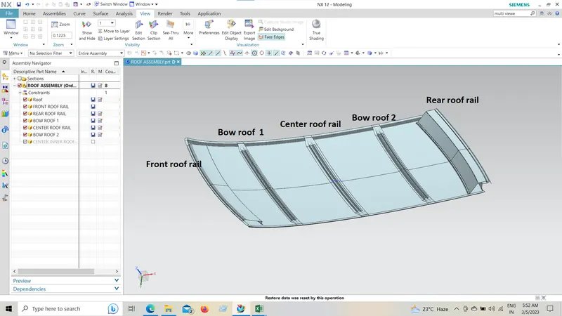
Bow roof prediction:
Now we have to analys position of bow roof supports using Bow roof prrediction formula,
W value need to be find.It should be less than 2.7
To get W value we need to find following values,
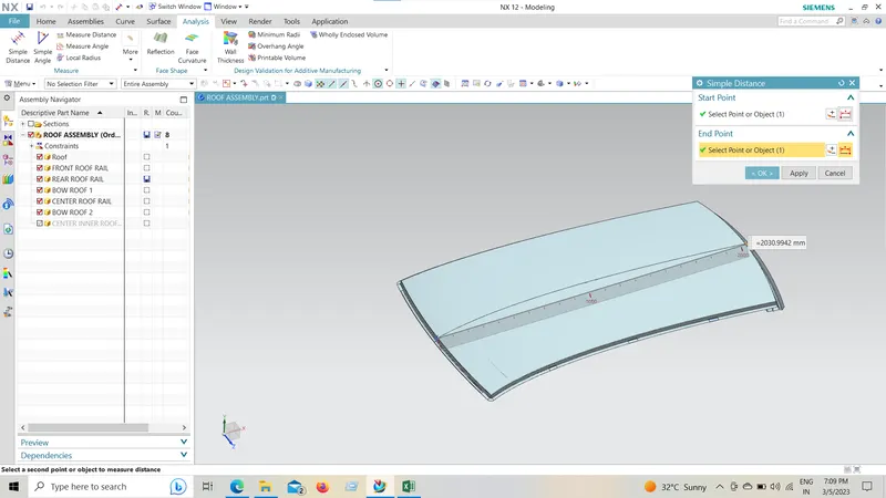
Roof length in x direction=2030mm
Roof curvature:
R=2(Rx*Ry)/(Rx+Ry)
We have offseted center horizontal line for 300mm in Z direction.
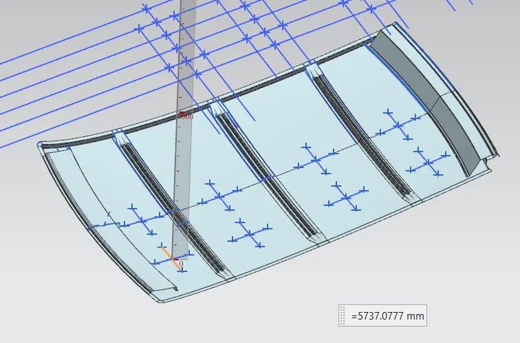
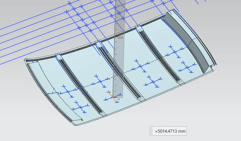
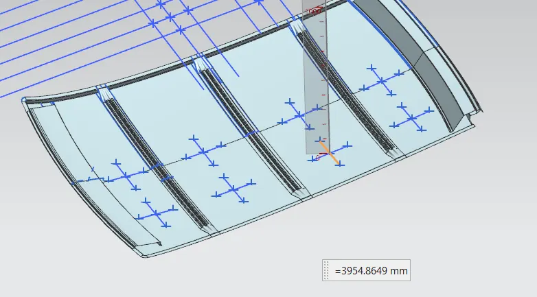
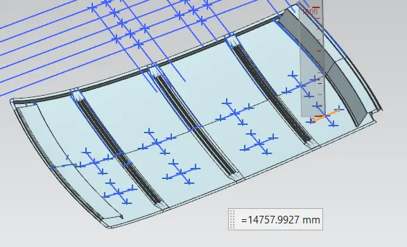
Then offseted 100mm on both side of that new line.Also center line between each supports created.The intersection points of that lines created.That points projected on roof inner surface.Then Curve created by using 3 point method by connecting those points.Lateral side curvature for Rx & longitudinal curvature for Ry.
Rx value for each curvature as shown below,
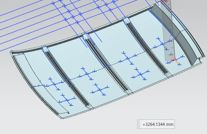
Ry value for all curvature,
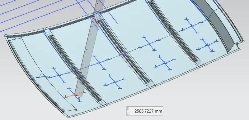
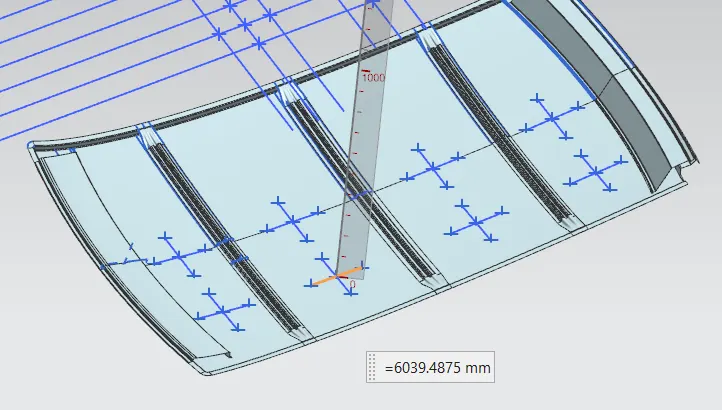
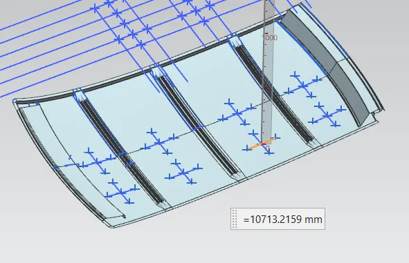
t is the thickness=0.75mm
l is bow roof span (Distance between adjacent supports)
Now we got all the parameters for W calculation.Substituted all the values respectively & we arrived table at each position of bow roofs.
| S NO | BOW ROOF | Rx | Ry | R | I | L | t | W | OK/NG |
| 1 | FRONT ROOF TO 1ST | 5737 | 2586 | 3565.032 | 289 | 2030 | 0.75 | 1.149916 | OK |
| 2 | 1st TO MIDDLE BOW | 5014 | 6039 | 5478.973 | 464 | 2030 | 0.75 | 1.342574 | OK |
| 3 | MIDDLE TO 2ND BOW | 3955 | 10713 | 5777.19 | 464 | 2030 | 0.75 | 1.342604 | OK |
| 4 | 2ND TO REAR ROOF RAIL | 3264 | 14758 | 5345.701 | 329 | 2030 | 0.75 | 1.19406 | OK |
Since all W<2.7 we found that ,Bow roof supports are OK.
Snow load criteria:
This is the load carrying capacity of the Top roof panel.
For this we need to calculate Qr value.It should be greater or equal to 3.1
Lx (Distance between left & right of roof panel at bow roof supports)
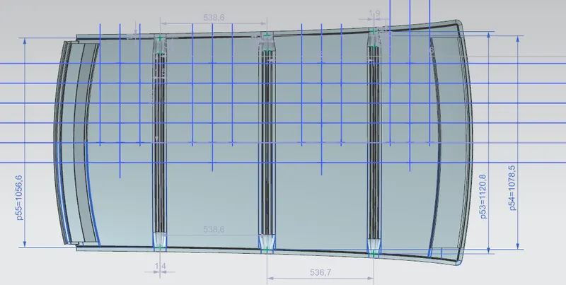
Y(Center distance between bow roofs)
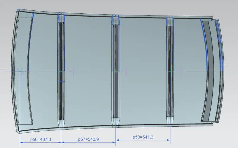
s value can be determined by this center distances
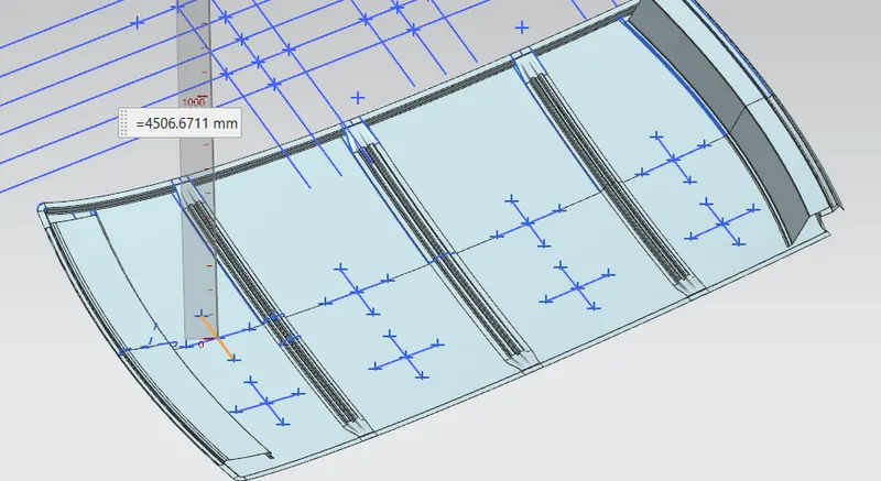
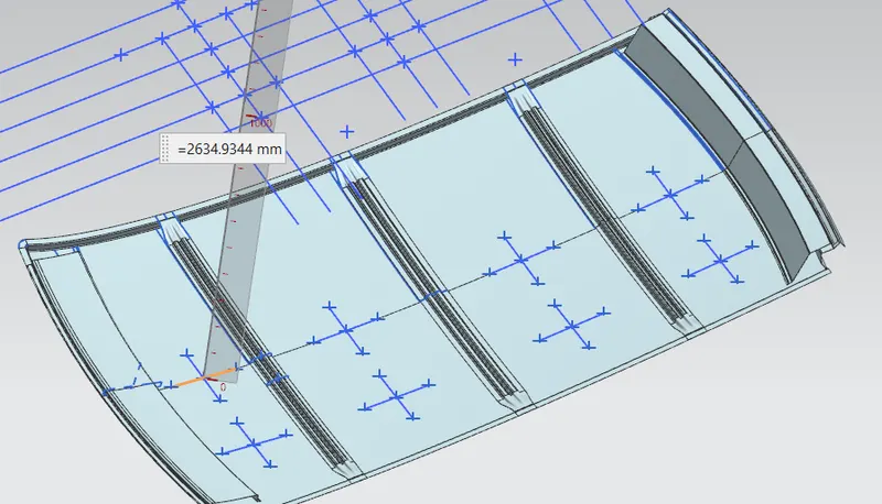
To find Rx & Ry we need to create center line in X direction.Offseted this line 100mm on both side.Then points created at intersection points.That points projected inside roof panel surface.Curv created by joining those respective points.
Rx as per shown below:
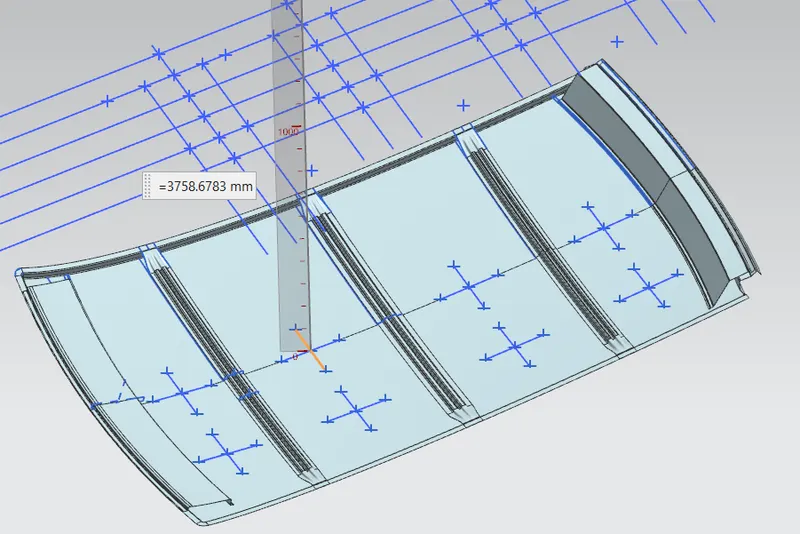
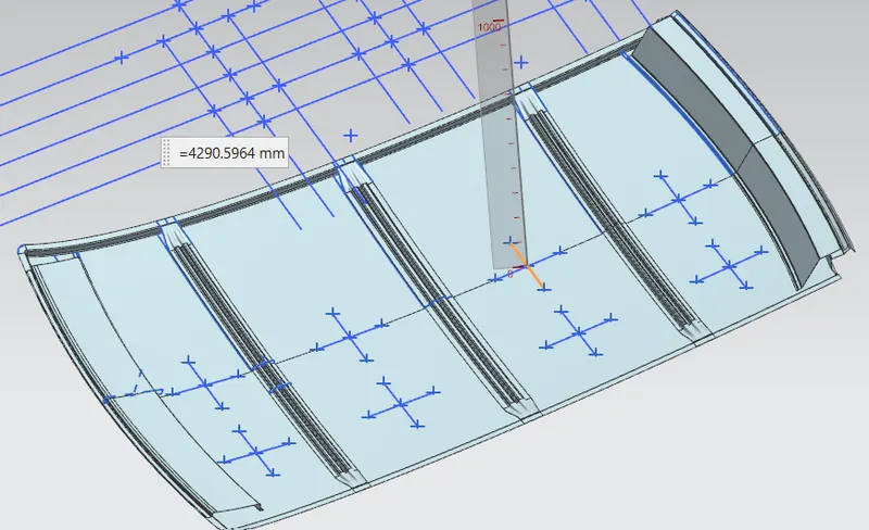
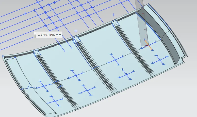
Ry value determined as below,
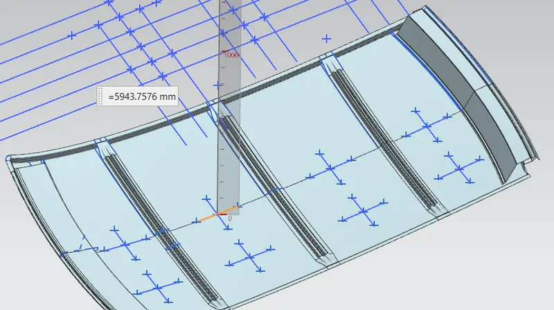
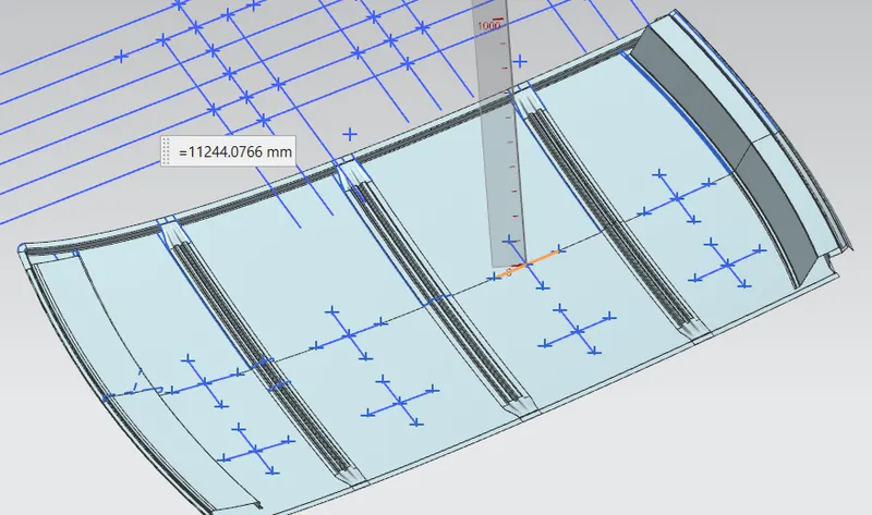
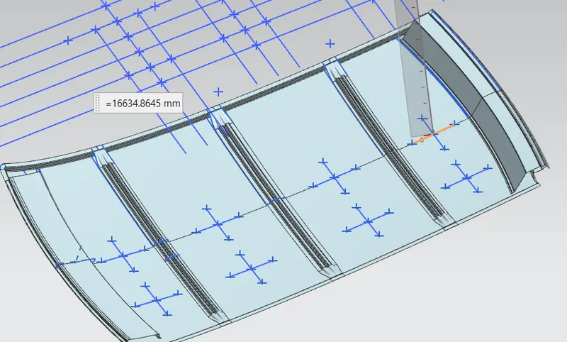
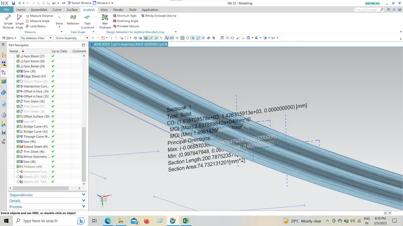
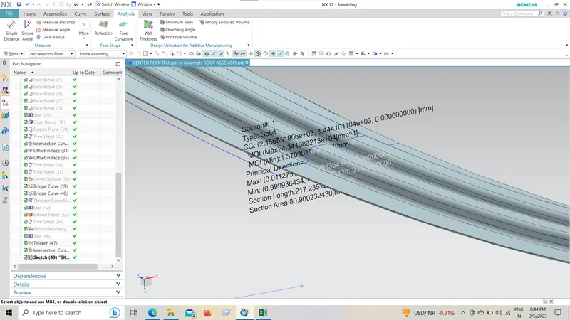
Then Moment of Inertia for each bow roof supports has to be find out,
Bow roof 1
Center roof support
Bow roof 2
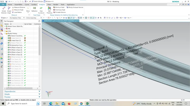
We have to consider minimum MOI value for each part
| S NO | BOW ROOF | Iy | α | Lx | Ly | y | s | Rx | Ry | t | Qr | OK/NG |
| 1 | FRONT ROOF TO 1ST | 1696.1 | 0.692084 | 1057 | 1929 | 407 | 474 | 4506 | 2635 | 0.75 | 22.8128 | OK |
| 2 | 1st TO MIDDLE BOW | 1370.3 | 0.874238 | 1079 | 1929 | 541 | 541 | 3759 | 5944 | 0.75 | 6.924035 | OK |
| 3 | MIDDLE TO 2ND BOW | 2544.65 | 0.941939 | 1120 | 1929 | 541 | 490 | 4290 | 11244 | 0.75 | 5.140734 |
OK |
Here all Qr value found greater than 3.1
Hence all bow roof supports passed snow load criteria.
I have attached table inside zip file.There values for each parameter substituted & required values found out using given formula for us.Proper formulas used for each parameter calculation.
Everything inside that excel file.That's why I did't done any calculation steps in report page.
That's all about Roof design.
Thank you.....