Roof Design
AIM:
Create an ASSEMBLY for the Provided Roof Style by making the reinforcements and the necessary flanges for the outer roof. Provide the proper dimensions and verify the Draft analysis. Calculations should be made to establish the location of the Bow-roofs after a study of the roof's curve.
Introduction:
The area of an automobile that is located above the passenger compartment and shields the occupants from the sun, wind, rain, and other environmental factors is known as the roof. Despite the fact that it merely appears to be a stylish surface that shields from the sun, wind, and other elements, different environmental variables are taken into consideration when constructing the same. The correct reinforcements should be installed for the roof's strengthening. High heat or loads during snowy circumstances may be applied to a vehicle's roof. Many calculations are made to make the roof durable under these circumstances. This guarantees the security of the car's occupants.
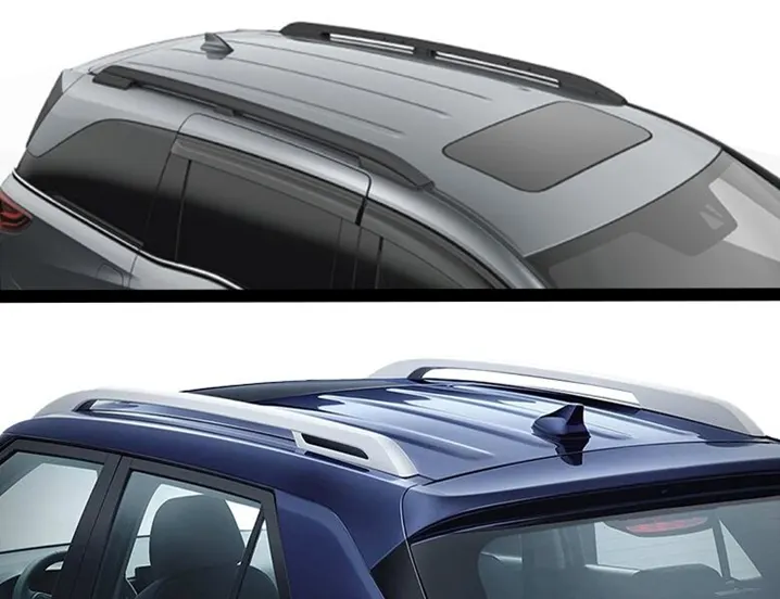
Design And Calculations
The specified style surface is used to design the roof and the roof reinforcements in NX CAD. All components are given a 0.75 mm sheet thickness. For the roof's stability, two bow roofs are offered.
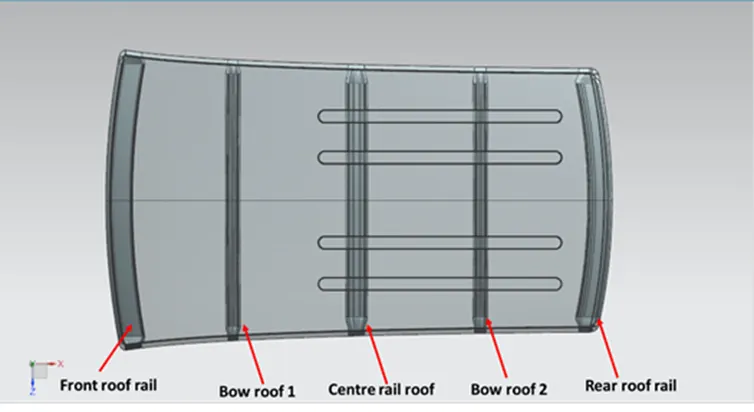
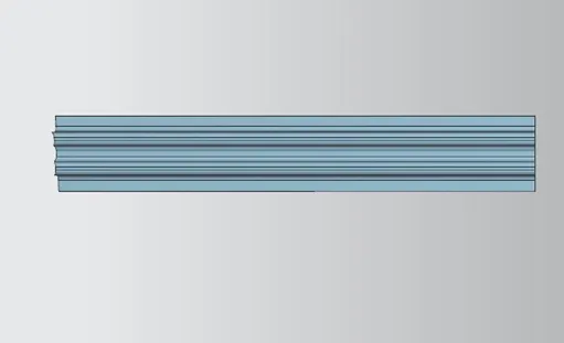
Roof rail in front:
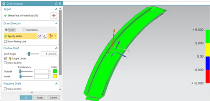
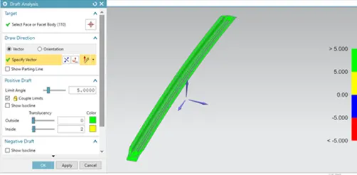
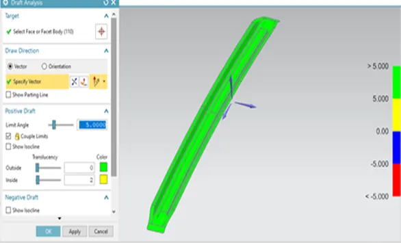
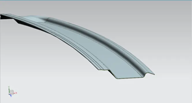
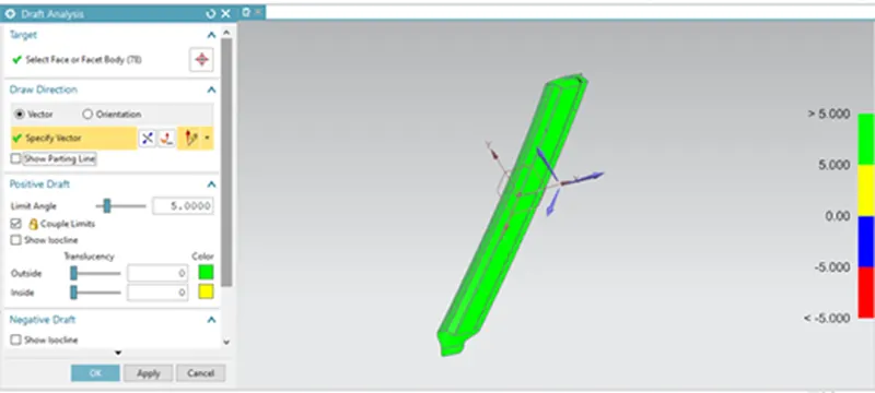
This is the frontal reinforcement offered. This component is attached to the windscreen and BIW body. When connecting it to the windscreen, visibility requirements are taken into consideration. Spot welds are used to secure it to the BIW, and mastic sealants are used to fasten the roof surface. The operation of deep drawing is given with a draught angle. The portion also undergoes a draught study to determine its manufacturing capacity.

Bow Roof 1
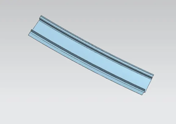
It serves as an additional layer of reinforcement to strengthen the roof. It is secured to the roof structure using mastic sealants.
Centre rail roof:
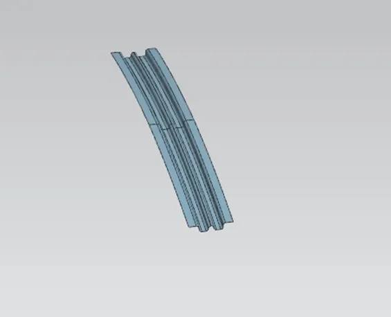
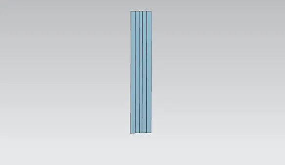
The centre rail roof serves as a structural link between the left and right halves of the roof. It is spot welded to the BIW and sealed to the roof with mastic sealants.
Bow roof 2
It is same as the bow roof 1
Rear Roof Rail:
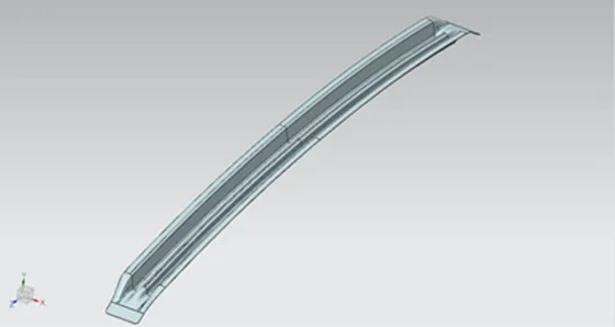
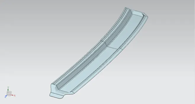
It is the reinforcement offered on the roof's back side. With this component, the backdoor and bodyside panels are joined. Furthermore, spot welds and mastic sealants are used to secure it.
Heat distortion study:
This study is done to check how the sheet metal components perform in the extreme heat conditions. Sheet metals have tendency to change its shape in high temperatures. To avoid any failure of sheet metal components this study is done to determine its capacity.
Bow – roof prediction Formula
W = [1.73 x 10^ (-3) x L] + [1.85 x 10^(-8) x (R^2)/t] + [ 1.10x10^(-3) x l] - 2.68
Judgement Condition: OK< 2.7> 3.1
Where,
L = Roof Length in X-Direction[mm] (Roof dimension in 0-Y)
R = Roof curvature
R = 2(Rx*Ry)/ (Rx + Ry)
Rx = X curvature
Ry = Y curvature
t = Roof plate thickness [mm]
l = Bow Roof Span [mm]
|
Sr No |
Section |
L (mm) |
Rx |
Ry |
R |
T (mm) |
I (mm) |
W |
Remark |
|
1 |
Front roof rail |
2029.65 |
2280.9 |
5873.5 |
3285.80 |
0.75 |
369.06 |
1.5035 |
ok |
|
2 |
1st bow roof |
2029.65 |
6189.9 |
4979.9 |
5518.9 |
0.75 |
435.69 |
2.0618 |
ok |
|
3 |
Centre roof |
2029.65 |
10443.4 |
4003 |
5787.591 |
0.75 |
436.14 |
2.1372 |
ok |
|
4. |
2nd bow roof |
2029.65 |
14784.6 |
3256..9 |
5337.911 |
0.75 |
392.78 |
1.966 |
ok |
Result table:
This shows the design is safe in heat distortion criteria.
SNOW LOAD PREDICTION FORMULA
Qr = [Iy x t2] / [α x s x [(Rx + Ry)/2]2 x 10-8]
Where,
α = My x Lx^2 x 10^-12, My = Y(Ly-Y)
Judgement condition = Qr ≥ 3.1
250 ≤ s ≤ 380
t = Roof plate thickness [mm]
Ly = Distance between the front and rear roof Rails on the Vehicle along with 0Y[mm]
Length of Roof panel with the centre point between Roof rail Front /Rear as the reference point of the front and the rear.
Lx = Distance between the Left and Right end of the roof on the Roof BOW [mm]
Width of the roof panel exposed on the surface.
Y = Distance front Front Roof Rail to Roof BOW[mm]
s = Distance for which Roof BOW bears divided load [mm]
s = L1/2 + L2/2
Iy = Geometrical moment of inertia of Roof BOW (Y cross-section) [mm4]
Rx = Lateral direction curvature radius of roof panel Y cross-section on Roof BOW [mm]
Roof panel curvature Radius of the Length Lx in Front view
Ry = Longitudinal Direction curvature radius of the Roof panel X cross-section on Roof BOW [mm]
Roof panel X curvature radius of length s in Side view
|
Result Table:
|

This shows that at the third section, design does not fulfil snow load criteria.
Hence, to increase the strength of the roof, embosses are provided on the roof surface.
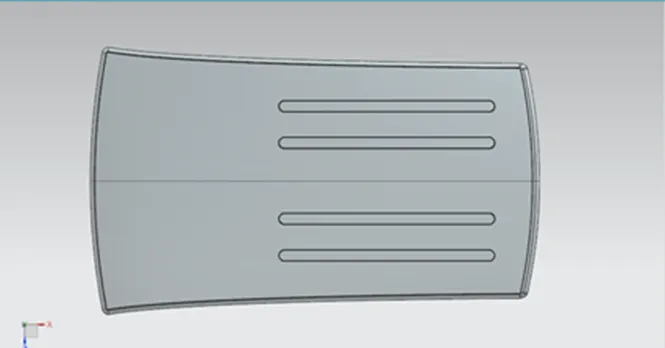
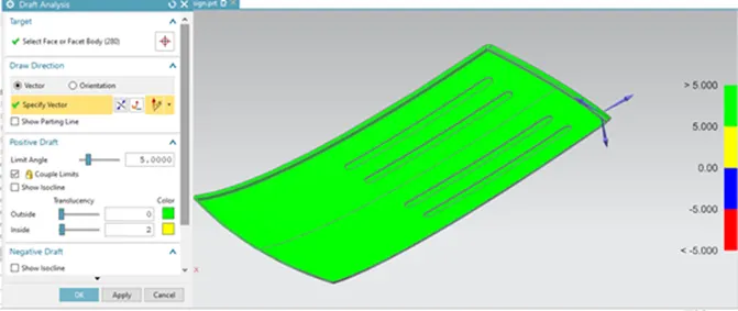
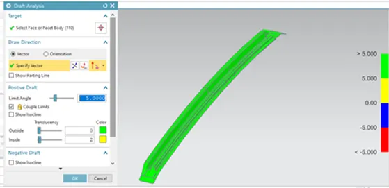
Draft analysis of roof was done to check for proper draft angle.
CONCLUSION:
Roof design was completed and evaluated for heat load and snow load requirements. The design met the requirements for the heat load but fell short in some areas for the snow load. On the roof surface, embosses are offered as a solution.