Roof Design
The Curvature Study of the Designed model is carried out and shown below.
Bow–Roof Prediction Formula (Heat Distortion Calculation)
W = [1.73 x 10^(-3) x L] + [1.85 x 10^(-8) x (R^2)/t] + [ 1.10x10^(-3) x l] - 2.68
Where,
L = Roof Length in X-Direction[mm] (Roof dimension in 0-Y)
R = Roof curvature
R = 2(Rx*Ry)/(Rx+Ry)
Rx = X curvature
Ry = Y curvature
t = Roof plate thickness [mm]
l = Bow Roof Span [mm]
Judgment Condition
OK< 2.7
Case-I
L = 2029.2422 mm
R = 2(Rx*Ry)/(Rx+Ry)
Rx = 5692.1634 mm
Ry = 2083.0927 mm
R = 2(5692.1634*2083.0927)/(5692.1634+2083.0927)
R = 3050.0098 mm
t = 0.75 mm
I = 516.5042 mm
W = [1.73 x 10^(-3) x L] + [1.85 x 10^(-8) x (R^2)/t] + [ 1.10x10^(-3) x l] - 2.68
W = [1.73 x 10^(-3) x 2029.2422] + [1.85 x 10^(-8) x (3050.0098^2)/0.75] + [ 1.10x10^(-3) x 516.5042] - 2.68
W = 1.6280
W(1.6280) < 2.7
Hence given criteria for bow roof heat distortion are satisfied
Case-II
L = 2029.2422 mm
R = 2(Rx*Ry)/(Rx+Ry)
Rx = 4833.5330 mm
Ry = 13699.5671 mm
R = 2(4833.5330*13699.5671)/( 4833.5330+13699.5671)
R = 7145.8427 mm
t = 0.75 mm
I = 287.5003 mm
W = [1.73 x 10^(-3) x L] + [1.85 x 10^(-8) x (R^2)/t] + [ 1.10x10^(-3) x l] - 2.68
W = [1.73 x 10^(-3) x 2029.2422] + [1.85 x 10^(-8) x (7145.8427^2)/0.75] + [ 1.10x10^(-3) x 287.5003] - 2.68
W = 2.4062
W(2.4062) < 2.7
Hence given criteria for bow roof heat distortion are satisfied
Case-III
L = 2029.2422 mm
R = 2(Rx*Ry)/(Rx+Ry)
Rx = 5672.5545 mm
Ry = 4081.3143 mm
R = 2(5672.5545*4081.3143)/( 5672.5545+4081.3143)
R = 4747.1374 mm
t = 0.75 mm
I = 419.1475 mm
W = [1.73 x 10^(-3) x L] + [1.85 x 10^(-8) x (R^2)/t] + [ 1.10x10^(-3) x l] - 2.68
W = [1.73 x 10^(-3) x 2029.2422] + [1.85 x 10^(-8) x (4747.1374^2)/0.75] + [ 1.10x10^(-3) x 419.1475] - 2.68
W = 1.8473
W(1.8473) < 2.7
Hence given criteria for bow roof heat distortion are satisfied
Case-IV
L = 2029.2422 mm
R = 2(Rx*Ry)/(Rx+Ry)
Rx = 4365.3568 mm
Ry = 4574.1332 mm
R = 2(4365.3568*4574.1332)/( 4365.3568+4574.1332)
R = 4467.3070 mm
t = 0.75 mm
I = 355.4454 mm
W = [1.73 x 10^(-3) x ] + [1.85 x 10^(-8) x (R^2)/t] + [ 1.10x10^(-3) x l] - 2.68
W = [1.73 x 10^(-3) x 2029.2422] + [1.85 x 10^(-8) x (4467.3070^2)/0.75] + [ 1.10x10^(-3) x 355.4454] - 2.68
W = 1.7136
W(1.7136) < 2.7
Hence given criteria for bow roof heat distortion are satisfied
Snow Load Prediction Formula
Qr = [Iy x t2] / [α x s x [(Rx + Ry)/2]2 x 10-8]
Note: The Qr value given over here is correct. There was a typo error in the formula given in the video.
Where,
α = My x Lx2 x 10-12, My = Y(Ly-Y)
t = Roof plate thickness [mm]
Ly = Distance between the front and rear roof Rails on the Vehicle along with 0Y[mm]
Length of Roof panel with the centre point between Roof rail Front /Rear as the front and rear reference point.
Lx = Distance between the Left and Right end of the roof on the Roof BOW [mm]
The width of the roof panel is exposed on the surface.
Y = Distance front Front Roof Rail to Roof BOW[mm]
s = Distance for which Roof BOW bears divided load [mm]
s = L1/2 + L2/2
Iy = Geometrical moment of inertia of Roof BOW (Y cross-section) [mm4]
Rx = Lateral direction curvature radius of roof panel Y cross-section on Roof BOW [mm]
Roof panel curvature Radius of the Length Lx in Front view
Ry = Longitudinal Direction curvature radius of the Roof panel X cross-section on Roof BOW [mm]
Roof panel X curvature radius of length s in Side view
Judgment condition
Qr ≥ 3.1
Case-I
t = 0.75 mm
α = My x Lx2 x 10-12
Y = 613.7666 mm
Ly = 1965.6246 mm
My = 613.7666(1965.6246-613.7666)
My = 829725.2883
Lx = 1129.4773 mm
α = 829725.2883 x 1129.47732 x 10-12
α = 1.058
s = L1/2 + L2/2
L1 = 613.7666 mm
L2 = 367.4695 mm
s = 613.7666/2 + 367.4695/2
s = 490.6180 mm
Rx = 6406.3931 mm
Ry = 2939.3733 mm
Iy = 1.7067 X 10^3
Qr = [Iy x t2] / [α x s x [(Rx + Ry)/2]2 x 10-8]
Qr = [1.7067 X 10^3 x 0.752] / [1.058 x 490.6180 x [(6406.3931 + 2939.3733)/2]2 x 10-8]
Qr = 8.4681
Qr(8.4681) ≥ 3.1
Hence given criteria for snow load are satisfied
Case-II
t = 0.75 mm
α = My x Lx2 x 10-12
My = Y(Ly-Y)
Y = 979.6518 mm
Ly = 1965.6246 mm
My = 979.6518 (1965.6246-979.6518)
My = 965910.0282
Lx = 1081.5808 mm
α = 965910.0282 x 1081.58082 x 10-12
α = 1.1299
s = L1/2 + L2/2
L1 = 367.4695 mm
L2 = 499.1276 mm
s = 367.4695/2 + 499.1276/2
s = 433.2985 mm
Rx = 2960.1084 mm
Ry = 6730.9924 mm
Iy = 2.3091 X 10^3
Qr = [Iy x t2] / [α x s x [(Rx + Ry)/2]2 x 10-8]
Qr = [2.3091 X 10^3 x 0.752] / [1.1299 x 433.2985 x [(2960.1084 + 6730.9924)/2]2 x 10-8]
Qr = 11.3083
Qr(11.3083) ≥ 3.1
Hence given criteria for snow load are satisfied
Case-III
t = 0.75 mm
α = My x Lx2 x 10-12
My = Y(Ly-Y)
Y = 1476.1868 mm
Ly = 1965.6246 mm
My = 1476.1868 (1965.6246-1476.1868)
My = 722501.6197
Lx = 1058.5030 mm
α = 722501.6197 x 1058.50302 x 10-12
α = 0.8095
s = L1/2 + L2/2
L1 = 499.1276 mm
L2 = 492.1049 mm
s = 499.1276 /2 + 492.1049/2
s = 495.6296 mm
Rx = 4267.7542 mm
Ry = 10976.0438 mm
Iy = 1.7150 X 10^3
Qr = [Iy x t2] / [α x s x [(Rx + Ry)/2]2 x 10-8]
Qr = [1.7150 X 10^3 x 0.752] / [0.8095 x 495.6296 x [(4267.7542 + 10976.0438)/2]2 x 10-8]
Qr = 4.1309
Qr(4.1309) ≥ 3.1
Hence given criteria for snow load are satisfied
| Heat Distortion Results | ||||||||||
| Sr. No. | Location | Rx | Ry | R | I | L | t | W | Criteria | Remark |
| 1 | Front Rail | 5692.1634 | 2083.0927 | 3050.0098 | 516.5042 | 2029.2422 | 0.75 | 1.628 | W < 2.7 | Satisfied |
| 2 | Roof Rail 1 | 4833.533 | 13699.5671 | 7145.8427 | 287.5003 | 2029.2422 | 0.75 | 2.4062 | W < 2.7 | Satisfied |
| 3 | Centre Rail | 5672.5545 | 4081.3143 | 4747.1374 | 419.1475 | 2029.2422 | 0.75 | 1.8473 | W < 2.7 | Satisfied |
| 4 | Roof Rail 2 | 4365.3568 | 4574.1332 | 4467.307 | 355.4454 | 2029.2422 | 0.75 | 1.7136 | W < 2.7 | Satisfied |
| Snow Load Results | |||||||||||||
| Sr. No. | Location | Iy | α | Lx | Ly | y | s | Rx | Ry | t | Qr | Criteria | Remark |
| 1 | Front Rail | 1.7067x10^3 | 1.05 | 1129.477 | 1965.6246 | 613.7666 | 490.618 | 6406.3931 | 2939.3733 | 0.75 | 8.4681 | Qr ≥ 3.1 | Satisfied |
| 2 | Roof Rail 1 | 2.3091x10^3 | 1.1299 | 1081.5808 | 1965.6246 | 979.6518 | 433.2985 | 2960.1084 | 6730.9924 | 0.75 | 11.3083 | Qr ≥ 3.1 | Satisfied |
| 3 | Centre Rail | 1.7150x10^3 | 0.8095 | 1058.503 | 1965.6246 | 1476.1868 | 495.6296 | 4267.7542 | 10976.0438 | 0.75 | 4.1389 | Qr ≥ 3.1 | Satisfied |
Manufacturing Technologies required for the production of Roofs are,
1. Bending- Bends are provided in the roofs at the location after studying visibility and headroom clearance for the passengers, they are provided to increase strength and specific angles of drafts are provided for the bends for ease of manufacturing.
2. Spot Welding- Spots are welded wherever required to keep the outer roof and roof rails in continuous contact. It is an alternative process of joining two metal parts together.
3. Mastic pads- They are provided between the outer roof and roof rails to reduce noise, vibration and harnesses of a vehicle, it also provides a type of contact between the outer roof and roof rails as sealant is applied at both ends.
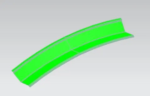
Draft Analysis are performed for the roof rails and the images are seen below,
1. Draft Analysis of Front Roof Rail
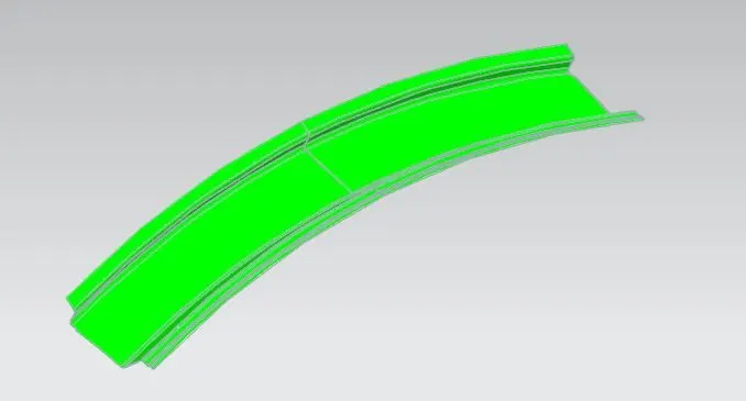
2. Draft Analysis of Front Bow Roof Rail.
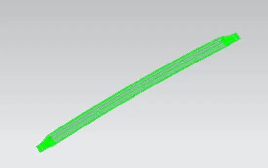
3. Draft Analysis of Centre Roof Rail
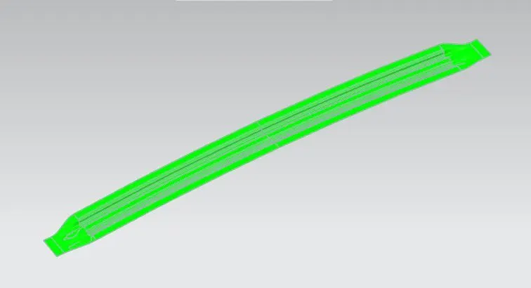
4. Draft Analysis of Rear Bow Roof Rail
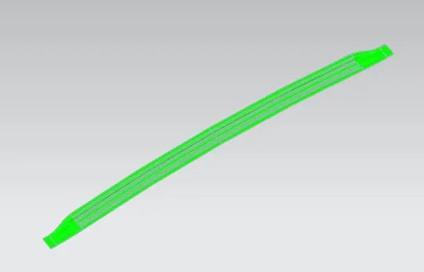
5. Draft Analysis of Rear Roof Rail
Conclusion
From the above tables, it is validated that from the given class A surface the parts modelled are satisfying heat distortion and snow load criteria, if the criteria are not satisfied then we have to provide the necessary embossed to the class A surface to enhance the strength of the roof.
Draft analysis is performed for all the rails and all the rails satisfy the manufacturing criteria and are producible without any modification.