Roof Design
ROOF
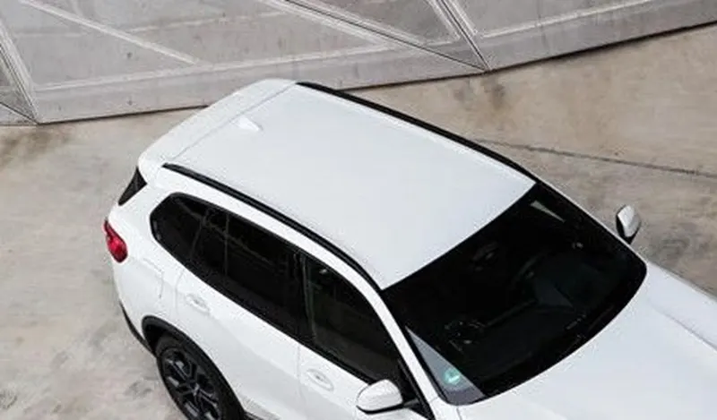
An automobile roof or car top is the portion of an automobile that sits above the passenger compartment, protecting the vehicle occupants from sun, wind, rain, and other external elementsl. Convertible roofs, Roof modules, Hardtops, Sunroofs, T-tops, Targa tops, Vinyl roofs are the different type of roofs in Automobile.nowadays there are at least three types of roofs commonly installed on cars, namely sunroofs, moonroofs, and also panoramic roofs.
The roof of the car must have high strength to resist the crush force to avail the passenger some space for survival.
ROOF PARTS AND STRUCTURE
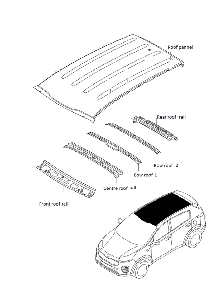
The main parts of car roof is roof panel ,front roof rail ,rear roof rail,and bow roofs .Car roof parts shown in the fig 2.2 . basicaly there are 3 primary roof rails in a car the front, the centre, and the rear, and the additional roof rails are called Bow roof rails.Position and number of reinforcement is based on the structure and size of the roof .
ROOF DESIGN CONSIDERATION
- Head room clearence
- Visibility criteria
- Heat distortion criteria
- Snow load criteria
- curvature study
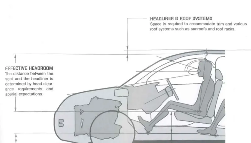
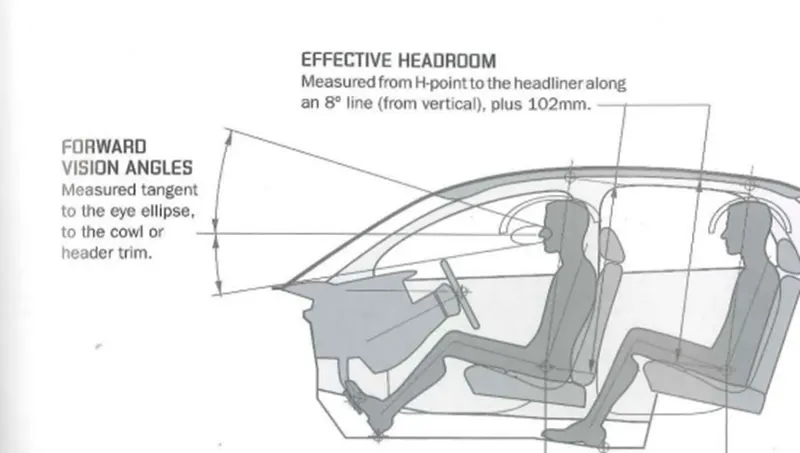
while designing the roof panel head room clearence and visibility criteria should be consider.based on this criteria proper angle and length provided for roof parts.
ROLLOVER TEST
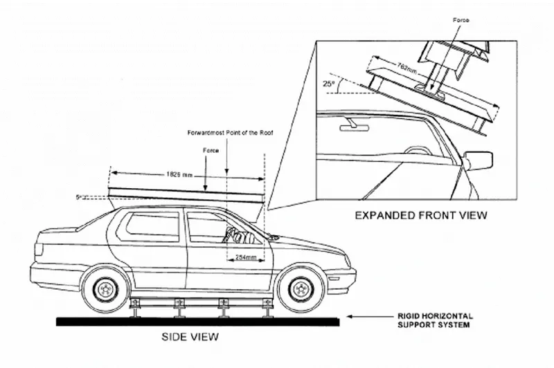
Rollover crashes, especially in the country, are usually very destructive events. Vehicle damage often includes deformation of the roof and its supporting structures. Head and neck injuries are common, and associated with roof deformation. Strengthening of the roof is suggested as an appropriate countermeasure for such injuries.Rollovers tend to be very severe crashes because of the energy required to roll a vehicle over unlike front and side crashes. This study is an effort towards reducing the severity of a rollover crash by strengthening the roof of a passenger car. The main focus of this thesis is to study the effect of reinforcing the roof of a car, in the event of a rollover.
heat disortion and snow load criteria calculation is used to provide proper reinforcement to roof .The position and number of bow roofs based on this criteria.
ROOF DESIGN
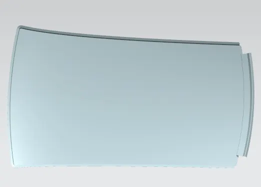
ROOF PANEL AND DITCH AREA
It is the outer surface designed by the styling team for the aesthetics of the vehicle.while design the roof ditch area visibility criteria should be consider based on this criteria proper open angle and length provided to front ditch area .windshield clearance and back door clearance also consider for designing of roof.bow roofs and centre reinforcement rails joined to ditch area by spot welding.
FRONT ROOF RAIL
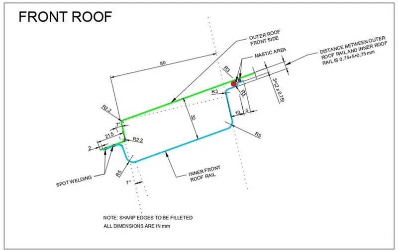
Front roof rail design based on Head room clearence and visibility criteria.it provides mounting provisions to windshield glass.one side of front roof rail joined by spot welding and the other end joined by mastic sealent ,so proper clearene provided for mastic.positive draft angle provided for undisturbed sheet metal forming process.There is no sharp corners in this design.Embosses are created to increase the strength of the roof rail.It is usually made from Body Side Outer scrap so thicknes of front roof rail is 0.75 mm .
BOW ROOF
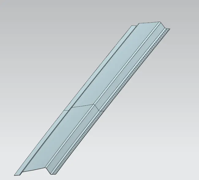
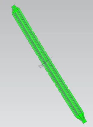
The bow roof rails provide additional support to the roof and they are positioned in such a way that they provide maximum support to the roof. The position of bow roof depends on the heat disortion and snow load criteria and curvature of roof .while designing the bow roofs head room clearence should be consider.Proper draft angle provided for uncomplicated sheet metal forming process. Bow roof fixed to roof with mastic sealent in addition ends spot welded to ditch area.
CENTRE ROOF RAIL
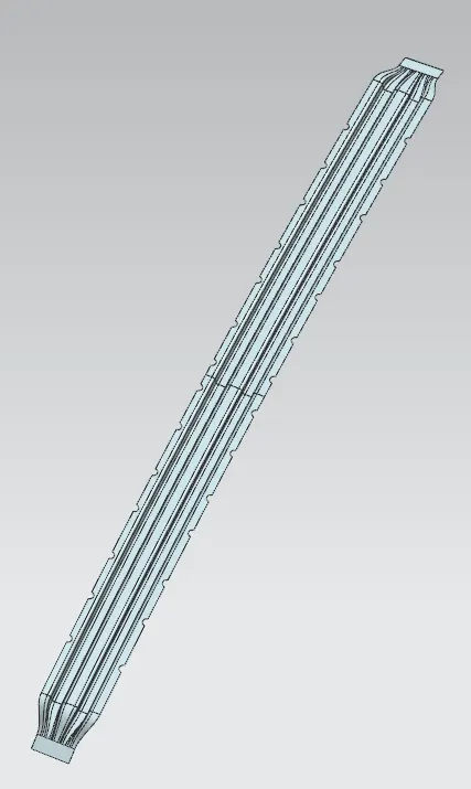
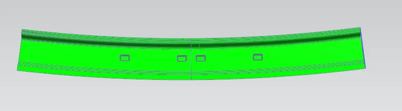
Centre roof rail is placed at the near centre of the roof to provide more strength and stiffness at the centre region. The position of centre roof rail also depends on the curvature of the roof .head room clearence and draft angle consider while designing the centre roof rail.it joined with roof by mastic and spot welding at the ditch area.The mastic points provided in the design .The thiknes of centre roof rail is 0.75 mm
REAR ROOF RAIL
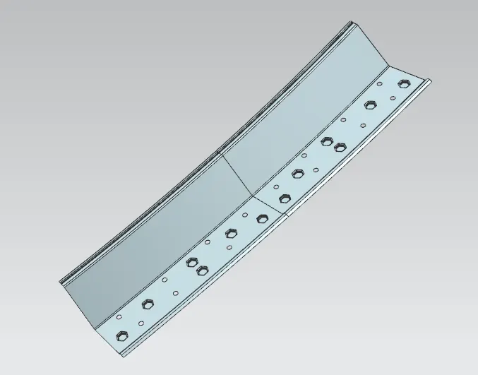
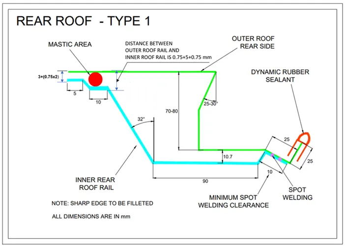
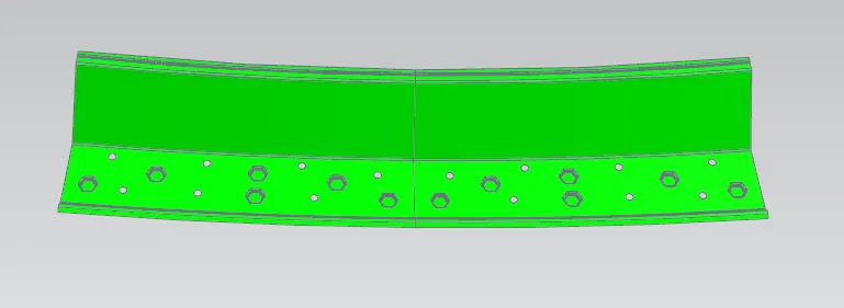
Head room clearence and rear visibility certeria should be consider while designing the rear roof rail. Appropriate draft angle is provided for trouble free sheet metal forming process.Inaddition accurate mastic and spot welding clearence provided in the design. Embosses are created to improve the strength of rear roof rail. one side of roof rail and roof joined by spot welding and the other end joined by mastic sealent.the thicknes of rear roof rail is 0.75 mm .
DRAFT ANALYSIS
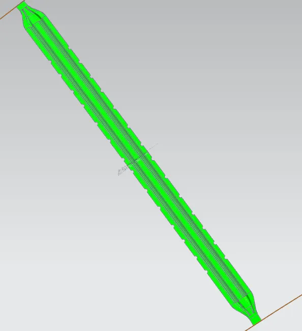
The Draft Analysis allows the user to easily analyze a part for proper draft angle. A Draft Angle describes the amount of taper for molded or cast parts perpendicular to the parting line.appropriate draft angle given for trouble-free forming of sheet matal. here all the roof parts checked.It has to be more than or equal to 7 degrees.
BOW ROOF 1
BOW ROOF 2
CENTRE ROOF

FRONT ROOF
REAR ROOF
HEAT DISTORTION AND SNOW LOAD CALCULATION
Bow–Roof Prediction Formula
W = [1.73 x 10^(-3) x L] + [1.85 x 10^(-8) x (R^2)/t] + [ 1.10x10^(-3) x l] - 2.68
Where,
L = Roof Length in X-Direction[mm](Roof dimension in 0-Y)
R = Roof curvature
R = 2(Rx*Ry)/(Rx+Ry)
Rx = X curvature
Ry = Y curvature
t = Roof plate thickness [mm]
l = Bow Roof Span [mm]
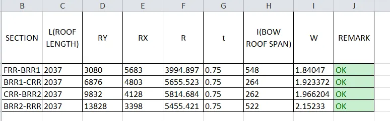
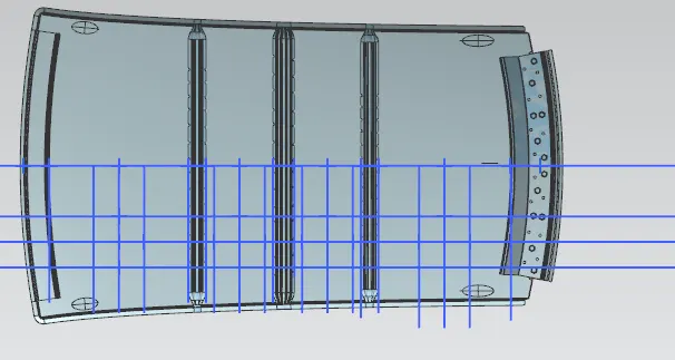
FRR- FRONT ROOF RAIL,BR- BOW ROOF ,RRR- REAR ROOF RAIL
In the above case all the value of "W" with in the judjment condition <2.7. so there is no modification needed.
Snow Load Prediction Formula
Qr = [Iy x t2] / [α x s x [(Rx + Ry)/2]2 x 10-8]
Note: The Qr value given over here is correct. There was a typo error in the formula given in the video.
Where,
α = My x Lx2 x 10-12 , My = Y(Ly-Y)
t = Roof plate thickness [mm]
Ly = Distance between the front and rear roof Rails on the Vehicle along with 0Y[mm]
Length of Roof panel with the center point between Roof rail Front /Rear as the front and rear reference point.
Lx = Distance between the Left and Right end of the roof on the Roof BOW [mm]
The width of the roof panel is exposed on the surface.
Y = Distance front Front Roof Rail to Roof BOW[mm]
s = Distance for which Roof BOW bears divided load [mm]
s = L1/2 + L2/2
Iy = Geometrical moment of inertia of Roof BOW (Y cross-section )[mm4]
Rx = Lateral direction curvature radius of roof panel Y cross-section on Roof BOW [mm]
Roof panel curvature Radius of the Length Lx in Front view
Ry = Longitudinal Direction curvature radius of the Roof panel X cross-section on Roof BOW [mm]
Roof panel X curvature radius of length s in Side view
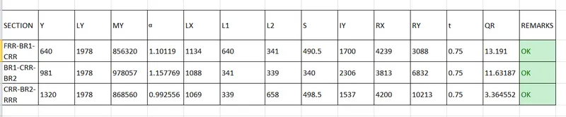
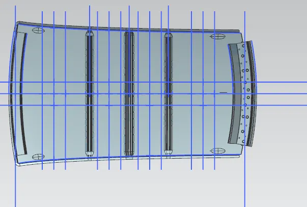
The above Snow load calculation Qr value with in the judgment condition Qr ≥ 3.1 .so here no altration required for the design.
CONCLUSION
The roof and reinforcement designed by following the master section as well as consider the head room and visibility criteria.draft analysis of designed parts checked.minimum draft angle provided for all the parts.
heat distortion and sow load criteria of design with in the judgment condition.In addition embosses are provided to increase the strength of the roof.