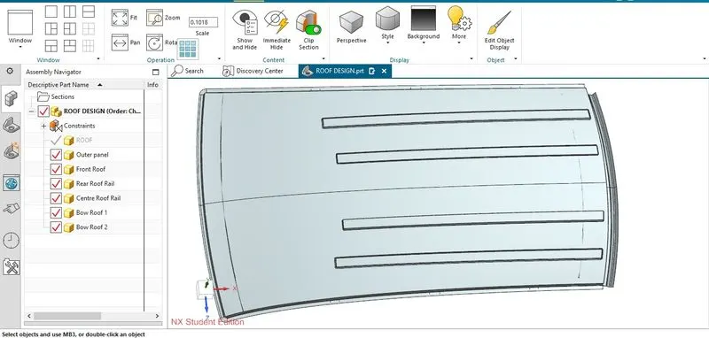
Roof Design
Report on the Roof design and draft analysis performed on it,
Aim: To create roof with its component out of given class A surface then perform the draft analysis on each component and then do required calculation to predict its strength.
Given Class A surface:
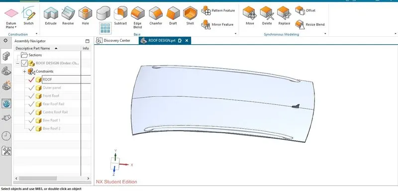
Roof we have designed consist of Componets like roof outer panel, 1 Front roof rail, 2 bow roofs , 1 centre roof rail and 1 rear roof rail with all design parameters as follows:
Step 1: Create the outerpanel following the mastersection to create the surfaces on the side as well as rear end.
- We have used law extension, untrim and offset surfaces to create surfaces on front with keeping the minimum draft angle of 7 deg in the mind.
- We have given the blends to avoid the sharp corners, the blend radius is acc. to mastersection and given 3.75 mm minimum radius wherever blend radius is not provided on the mastersection.
- Used through curve mesh command to the corner where A- pillar going to attach in the car.
- Similarily we worked on the rear part following the mastersection.
- We worked only on the half surface and used mirror geometry to create the full outer panel, finally thickened the surface to create solid surface.
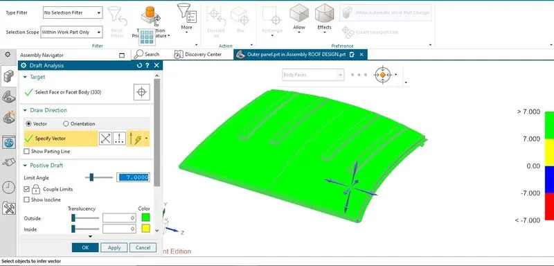
- Now perform the draft analysis on finally created solid surface
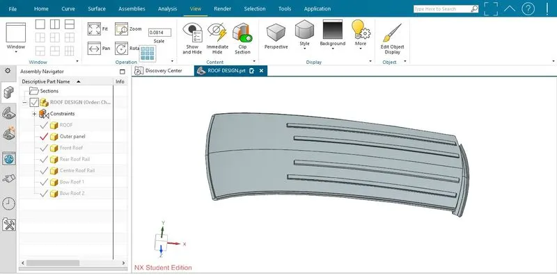
- Our outer panel will look like this:
- Draft analysis performed on solid surface:
Step 2 Create Front Roof rail by following the mastersection given for it.
- We have used Offset surface, offset curve on face, trim sheet to create flanges on FRR, used law extension to create side wall with giving them Minimum draft angle of 7 deg.
- Used offset surface, trim and extend to create the bottom surface.
- Given the blends following the mastersection.
- Applied the offset curve, law extension and trim and extend to create a side wall.
- Finally Mirrored the half part to create full rail then finally thickened to soild surface.
- Our front roof rail will look like this:
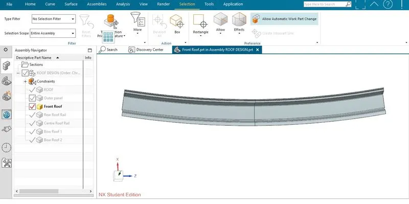
- Finally performed the draft analysis and increased the draft angle greater then 7 deg wherever the draft is not clearing on the surface. So our final draft analysis is lool like this:
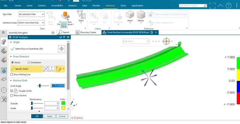
Step 3 : Creating the Bow roofs, bow roof 1 and 2 are created in the same way
- We have used command like offset surface, offset curve on surface and trim sheet to create flanges on the wall of bow roof.
- Used law extension, trim and extend command to create the side wall of the bow roof with keeping minimum draft angle of 7 deg in the mind.
- Applied the offset surface, trim and extend sheet to create the bottom surface.
- Used Law extension and offset surface to create the mid section of BRR.
- All dimensions are given acc. to the mastersection, since blends are not provided in the mastersection so we take minimum of 3.75mm radius for the blend.
- Also we created swept surface for the ditch area where bow roof are going to attach with the outer panel.
- Finally mirrored and thickened to create full Bow roof.
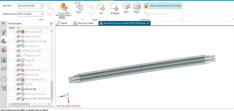
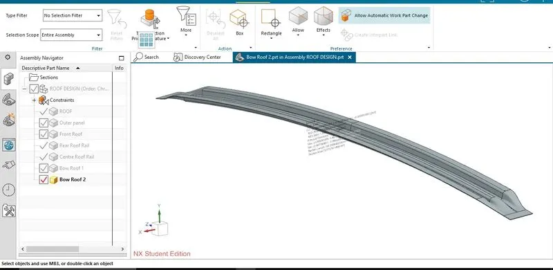
- Our bow roofs will look like this:
- Bow roof 1:
- Bow roof 2:
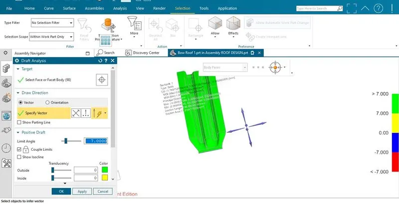
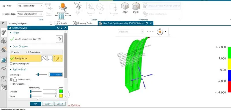
- Now perform the draft analysis and make the necessary changes on the surface to clear the minimum draft of 7 deg, so our final draft analysis will look like this:
- Draft anlaysis of Bow roof 1:
- Draft analysis for bow roof 2:
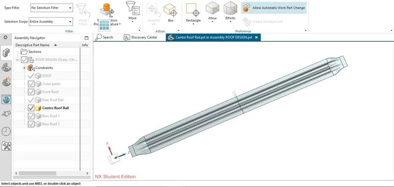
Step 4: Create the centre roof rail in the same way we created the bow roofs but dimensions are different than the bow roof dimensions.
- Our Center roof rail look like this:
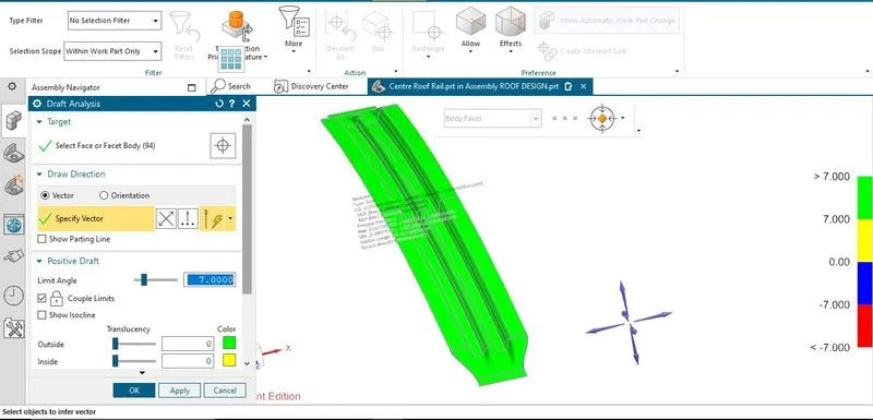
- Draft analysis perfomed on the centre roof rail and make necessary changes on the draft angle if our draft is not clearing, so our final draft analysis will look like this:
Step 4: Create rear roof rail by following the given mastersection.
- Starting from end we use wave geometry linker ,offset surface, trim and extend , law extension command to create the end surface of rail by following the master section.
- And we create the front walls and surface by using the law extension, offset surface, trim and extend.
- Then provide the edge blend to avoid the sharp surface since blend radius is not given on the mastersection we take the minimmum radius of 3.75mm.
- Also we give minimmum draft angle of 7 deg wherever required.
- We have given all the dimension following the mastersection.
- Finally Mirror and thicken to create the full rear rail.
- Our Rear Rail will look like this:
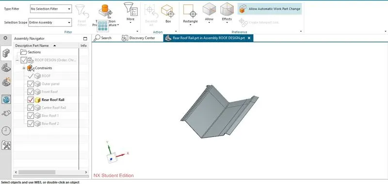
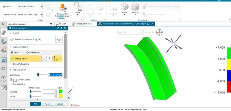
- Also after performing the draft analysis and making the necessary changes for clearing the draft, our final draft analysis will look like this:
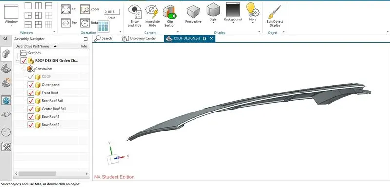
So our final roof design will look like this:
Calculations:
Heat-Distortions calculations:
After measuring the all variable for the given formula equation i.e.,
Given formula is W = [1.73 x 10^(-3) x L] + [1.85 x 10^(-8) x (R^2)/t] + [ 1.10x 10^(-3) x l] -2.68
where all values for variable are taken acc. to screeshot shown below:
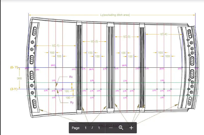
So After measuring each variable from our roof design and dividing the design into four section we get the values as shown:
t= 0.75mm (same for all 4 sections), L = 2030.6982 mm
l for four cases is given by l= 479.8786 mm (for case 1), l= 432.0481mm (for case 2), l= 432.2602 mm( for case 3), l = 242.6701 mm( for case 4)
Rx and Ry for the four cases is given by For case 1, Rx= 3995.97070 mm and Ry= 3614.99193mm
For Case 2, Rx= 4767.59522 mm and Ry = 3415.7284 mm
For Case 3, Rx = 3810.78967 mm and Ry= 11443.66895
For Case 4, Rx = 2598.06741 mm and Ry= 7067.096
Calculation For case 1:
R= 2(Rx*Ry)/(Rx+Ry) = 14445401.83*2/7610.9263 = 3795.946 mm
l = 479.8786 mm, L= 2030.6482 mm, t=0.75 mm
So, W= [1.73 x 10^(-3) x 2030.6982] + [ 1.85 x 10^(-8) x (3795.946)^2] + [1.1 x 10^(-3) x 479.8786] - 2.68
= 3.5131 + 0.352 + 0.5278 - 2.68 = 1.713 < 2.7 so this section is ok.
Calculation for case2 :
R = 2(Rx*Ry)/(Rx+Ry) = 3979.99mm, L=2030.6982, l= 432.0481 mm, t=0.75mm
W = [1.73 x 10^(-3) x 2030.6982]+ [1.85 x 10^(-8) x (3979.99)^2] + [ 1.10 x 10^(-3) x 432.0481] - 2.68
= 3.5131 + 0.39 + 0.4752 -2.68 = 1.6898 < 2.7 means this section is ok.
Calculation for case 3:
R = 2(Rx*Ry)/(Rx+Ry) = 87218829.24/15254.4585 = 5717.5958 mm, L= 2030.6982 mm, l = 432.2602mm, t=0.75mm
so W = 3.5131 + 0.8063 + 0.4755 - 2.68 = 2.12 <2.7 means this section is ok.
Calculation for case 4 :
R= 2(Rx*Ry)/(Rx + Ry) = 3799.3754 mm, L = 2030.6982 mm , l = 242.6701 mm, t=0.75 mm
So, W= 3.5131 + [1.85 x 10^(-8) x(3799.3754)^2/0.75] + [ 1.1 x 10^(-3) x 242.6701] - 2.68 = 3.5131+ 0.3561 + 0.2669 -2.68 = 1.456 < 2.47 means this section is ok.
Calculations for Snow Load Prediction:
So Given Formula is, Qr = [ ly x t^2]/ [ a x s x [(Rx + Ry)/2]^2 x 10^(-8) ]
where a = My x Lx^2 x 10^(-12), My = Y(Ly -Y) after measuring other varible for three sections taking reference from below screen shot i.e.,
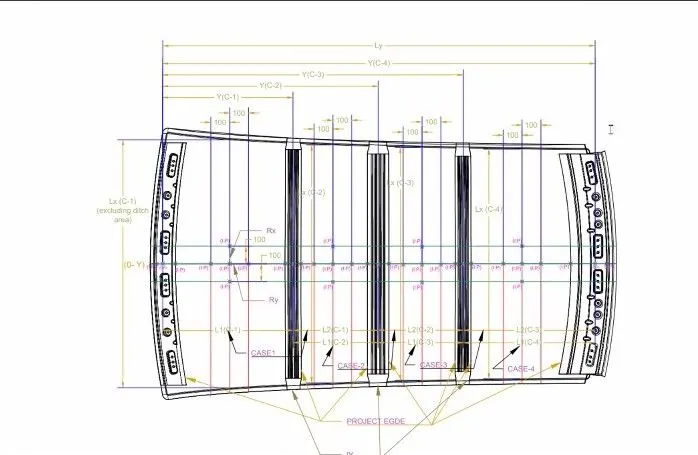
So We have t= 0.75 mm ( Same for all cases) , Ly = 1918.0530 mm , Iy for all cases are such that Iy = 1.8585 x 10^3 mm^4 (for case 1), Iy= 2.5544x 10^3 mm^4(for case 2), Iy=1.8860 x 10^3 mm^4 (for case 3)
Y for all Cases are such that Y= 550.3820 mm (for case1), Y= 1059.2931 mm (case2), Y= 1568.0377 mm (case 3) , Y= 1918.0530 mm (case 4).
Lx for all cases are such that Lx= 1139.2230 mm (for case1), Lx = 1087.4561 mm (for case 2), Lx = 1061.2850mm (for case 3)
L1 and L2 for all cases are such that , L1 =550.3820 mm and L2 = 508.9111mm (for case 1)
L1= 508.9111 mm and L2= 508.7446mm (for case 2), L1=508.7446 mm and L2= 350.0153 mm (for case 3)
Rx and Ry for all cases are such that Rx = 4350.8723 mm and Ry = 2879.4060 mm (for case 1)
Rx= 3824.9564 mm and Ry= 6970.7990 mm (for case 2)
Rx = 4331.1564 mm and Ry = 12165.01844mm (for case 3)
So calculation for case 1,
My= Y(Ly-Y) = 752741.50 mm^2, a= My x Lx^2 x 10^(-12) =0.977, s=L1/2+L2/2 = 529.65 mm, (Rx+Ry)/2 = 3615.14 mm
Qr = 15.46>= 3.1 but s is not satisfying 250
Calculation for case 2,
My=909678.4366 mm, a=1.07 , s= 508.828 mm , (Rx + Ry)/2 = 5397.878
Qr = 9.057 >=3.1 but s is not satisfying the required condition so our section would fail.
Calculation for case 3,
My= 548837.186mm , a =0.618 , s= 429.38 mm , (Rx +Ry)/2 = 8248.087 mm
Qr = 5.877 >= 3.1 but s is not satisfying the required condition so this section would fail.
Conclusion: So from above calculation we can say that our roof design can handle the heat distortion but it would fail in carrying the load of snow therefore to improve the strength of our roof we would apply emboss on the top surface, so our final design will look like this: