Roof Design
ROOF DESIGN
AIM: To design a roof assembly along with the reinforcements for a vehicle by using the given roof styling skin data, according to the vehicle norms and engineering standard and finally need to perform some calculations to find the roof strength and durability .
Introduction:
Roof:
An automobile roof is considered as an integral part of BIW (body in white) design. The car roof is the region above the passenger compartment that protects the occupants from the sun, wind, rain, and other external elements.The roof can be made of various materials including steel, aluminum, and even glass. Some cars have a sunroof, which is a panel that can be opened to let in natural light and fresh air. There are also convertibles which have retractable roofs that can be folded down to create an open-air driving experience.
Roof design also plays an important role in the overall look of a car. Many modern cars feature sleek and aerodynamic roof-lines that improve the vehicle's fuel efficiency and performance. Some cars also come with panoramic sunroofs which are quite large and stretch over the entire length of the cabin, providing a unique and immersive driving experience.
Additionally, the roof can also be used to mount solar panels, which can help to charge the car's battery and reduce the vehicle's environmental impact. The roof can also be used to mount other types of equipment such as bike racks, cargo boxes, and even a rooftop tent for camping.
Overall, the automobile roof is a crucial element of a car, serving both practical and aesthetic purposes. It provides protection from the elements, enhances the vehicle's structural integrity and adds to the overall design of the car.
Types of Roofs:
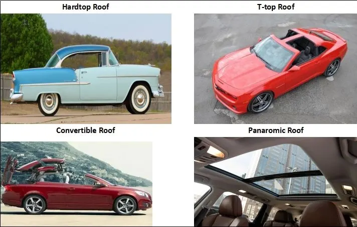
There are several types of roofs commonly used in automobiles, they are:
- Hardtop roof:A hardtop roof is a solid roof made of metal or composite materials, with no retractable or removable sections.
- Convertible roof:A convertible roof is a roof that can be opened or removed to transform the car from a closed vehicle to an open-air vehicle. There are several types of convertible roofs, including soft-top, retractable hardtop, and targa top.
- Sunroof:A sunroof is a panel in the roof that can be opened to allow in sunlight and fresh air. Sunroofs can be fixed or retractable, and can be located in the front or rear of the vehicle.
- Moonroof:A moonroof is a type of sunroof that has a tinted, tempered glass panel that can be opened to allow in sunlight and fresh air.
- T-top roof:A T-top roof is a roof that has two removable panels on either side of a central bar. T-tops provide an open-air experience while retaining the structure of a hardtop roof.
- Panoramic roof:A panoramic roof is a large, glass roof that covers a significant portion of the vehicle's roof and provides an unobstructed view of the sky.
Difference between a sunroof and a moonroof?
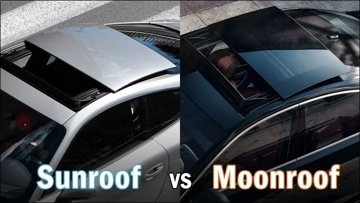
Most of them interchanges the terms, but there is a difference between these two concepts. Both are roof panels of a car that let light or fresh air inside the vehicle’s cabin space. But that’s where the similarities end.
A sunroof is typically a solid body-colored panel that can manually tilt up or can be removed. A sunroof is an opaque metal panel, and you can’t see through it and from outside, it looks like a body-colored metal panel.
A moonroof is a also a type of sunroof, except that it’s a transparent, sliding, tinted glass panel. This panel is not removable. In recent times, the panoramic style of moonroof has become popular, in which most of the roof of the car is made of glass, but only the panel over the two front seats will slide or open and the roof glass over the rear seats are stays fixed. The interior of the car is then shielded by a retractable shade in the headline. Now-a-days, majority of new cars have moonroofs, as technically considered, the sunroof has pretty much gone out of style.
Essential and Non-Essential parts of Roof Assembly:
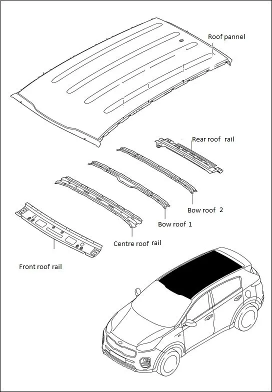
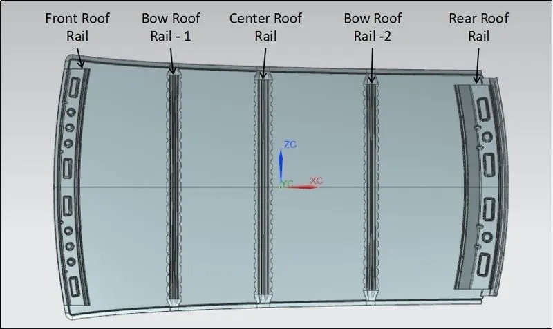
A roof panel assembly includes a roof outer panel, ditch area and inverted hat like reinforcements rails which underlie the inner side of the roof panel.
1. Reinforcement Rails:
Reinforcement roof rails in an automobile roof serve two main purposes:
- Structural support:Reinforcement roof rails provide additional support to the roof structure, helping to distribute the weight of the roof and protect the vehicle from damage during a rollover accident.
- Improved safety:Reinforcement roof rails help to prevent the roof from crushing in a rollover accident, which can reduce the risk of injury to the occupants of the vehicle.
2. Ditch area:
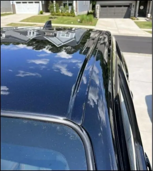
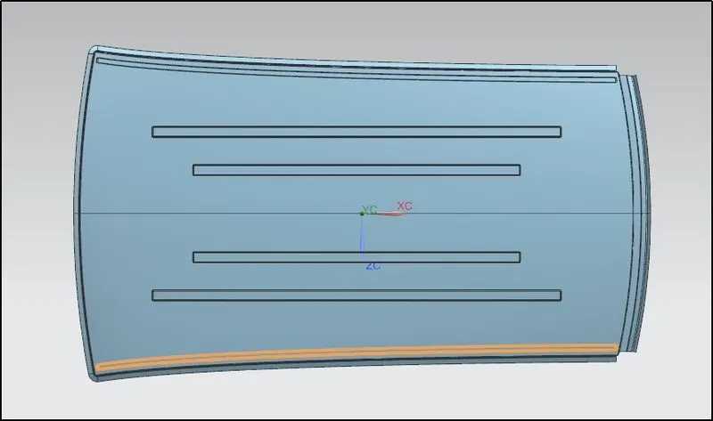
The purpose of ditch area is to provide a channel for water to run off the roof, preventing water from entering the interior of the vehicle. This helps to keep the interior of the vehicle dry and protects it from water damage. The ditch area also enhances the aerodynamics of the vehicle, helping to reduce wind resistance and improve fuel efficiency.for the run flow of fluid present on the roof.
3. Roof Rails/Racks:
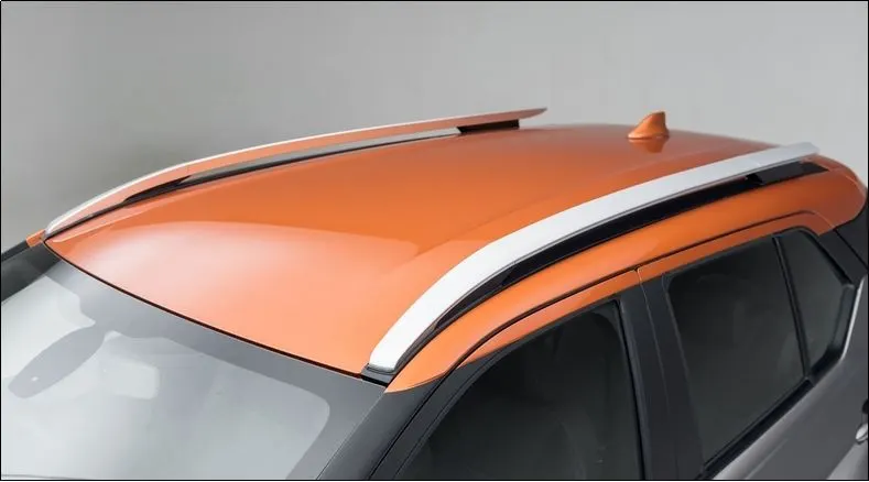
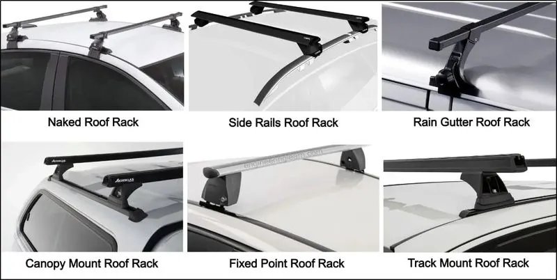
The purpose of roof rails in the automobile roof panel is to provide a sturdy mounting point for roof-mounted accessories such as luggage racks, bike carriers, and cargo boxes. Roof rails are typically mounted on the roof of the vehicle and extend along the sides of the vehicle, providing a secure and stable platform for attaching accessories. Roof rails also add a sporty and stylish appearance to the vehicle and can be used to enhance its overall aesthetic appeal.
Design Considerations of Roof:
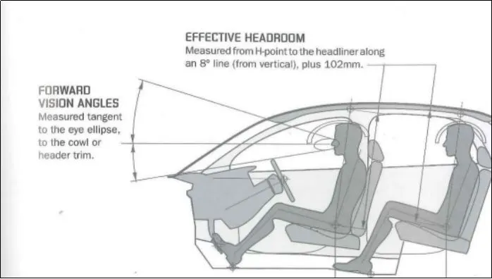
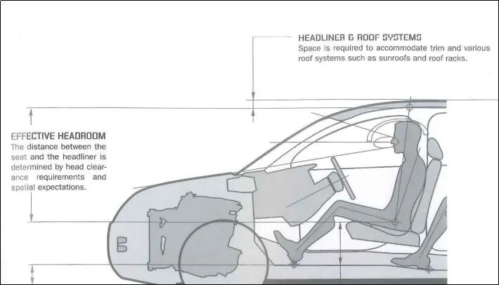
- Visibility criteria
- Head room clearance
- Curvature study
- Bow roof position
- Heatdistortion
- Snow load criteria
- Draft analysis
Roof Design:
Data to be used:
Roof Thickness Information
Roof Panel Thickness = 0.75mm
Reinforcement (Roof Rails) Thickness = 0.75mm
1. Roof Outer Panel:
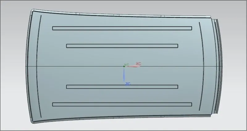
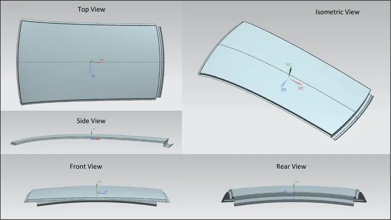
The outer panel is a metal cover which covers the entire area between the front windshield and the back door with a good aesthetic styling surface, roof lines and ditch area. The styling team designs the skin data of the roof’s outer panel by considering the shape and size required to cover the top portion of the vehicle with aerodynamic aspects, in order to improve the fuel efficiency and performance. The length and width of the outer panel is depends on the type of the vehicle and the seating capacity. The outer panel is attached to the inner reinforcement rail panel by spot welding and mastic sealants. The spot welding is applied in the non-visible are like front and back roof rails and mastic sealants are applied in between centre and bow roof rails to improve the strength of roof and also to reduce vibration. In case sun roof are required a dedicated cut out is provided on the roof panel and sealed with the glass.
Various views:
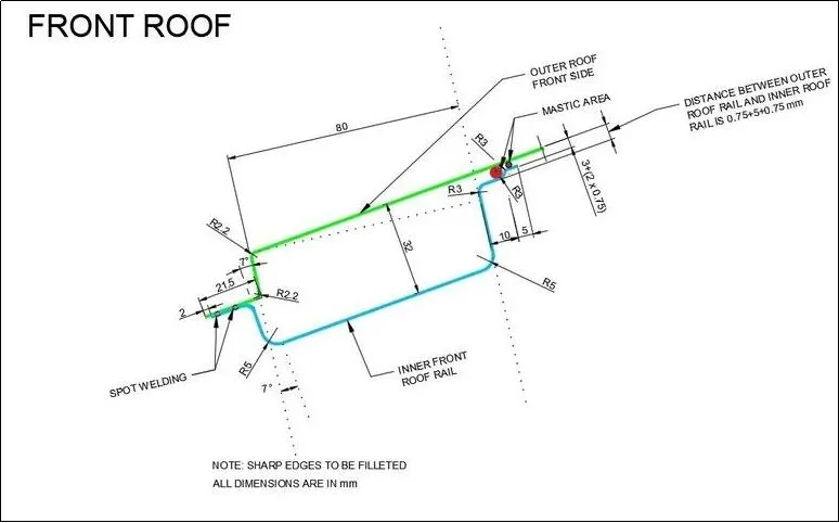
2. Front Roof Rail:
Front roof rail refers to the structural component of a car that runs along the front edge of the roof. The roof rail helps to provide support and stability to the roof, as well as serving as a mount for other components such as the front windshield and sunroof. The front roof rail is typically made of steel or aluminum, and is designed to be both strong and lightweight. It is also an essential part of the car's overall safety system, helping to protect the occupants in the event of a rollover accident. Additionally, some front roof rails are equipped with crossbars that can be used to mount cargo carriers, bike racks, and other types of equipment.
Front Roof Rail Master Section:
Design Points:
- The dimension 21.5 mm and the angle (min) 7 degrees is to be maintained for the windshield attachment.
- The dimension 32 mm gap along the 80 mm length of roof panel ismaintained for the visibility criteria. Otherwise, it may hide the road view for the driver.
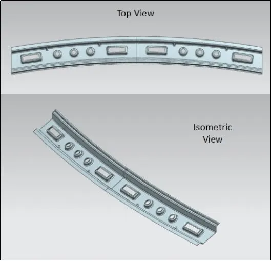
Various views:
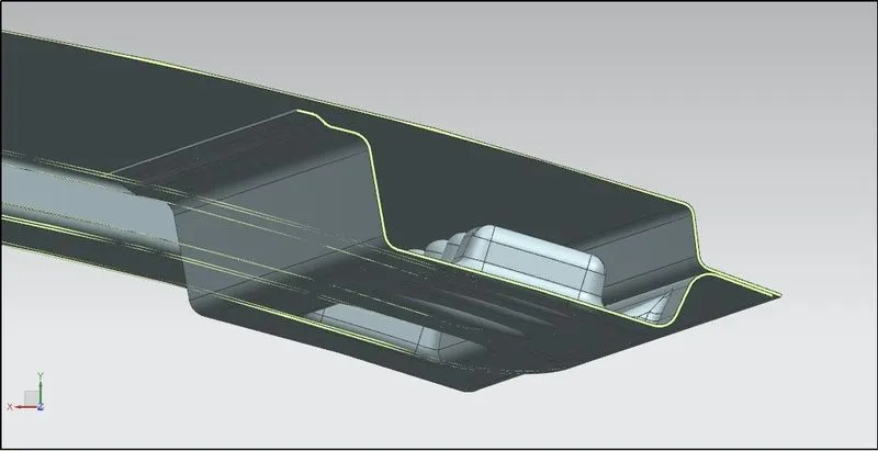
Sectional View:
3. Rear Roof Rail:
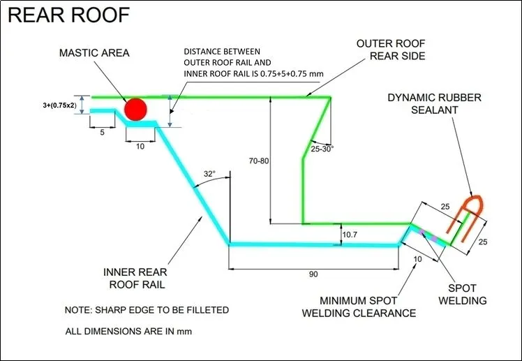
The rear roof rail is a structural component of a vehicle that is located at the back part of the roof. Its main function is to provide support and stability to the vehicle's body, helping to distribute the weight of the car, passengers, and cargo evenly throughout the car's structure. The rear roof rail is typically made of metal, such as steel or aluminum, and is designed to withstand the stress and weight placed upon it. In addition to its structural role, the rear roof rail may also serve as a mounting point for various car accessories, such as roof racks, bike carriers, and back door. The rear roof rail is a critical component of a vehicle and plays an important role in maintaining the overall safety and stability of the car.
Rear Roof Rail Master Section:
Design Points:
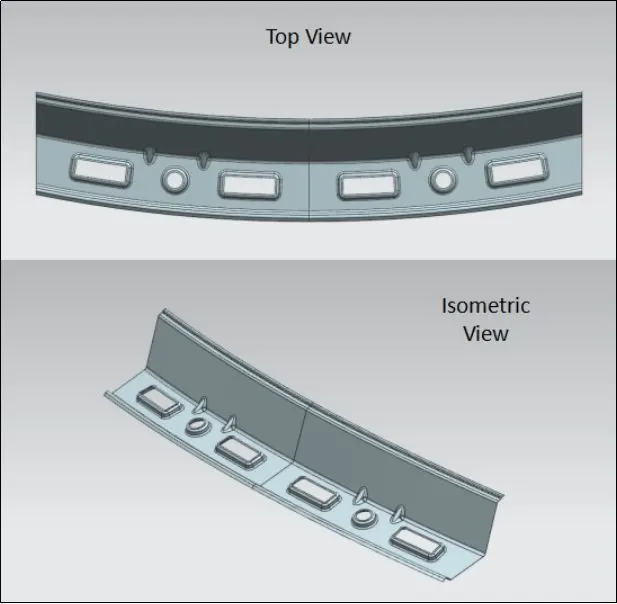
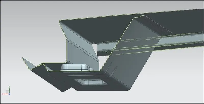
- The dimension 70 to 80 mm down and the angle 25 to 30 degrees is fixed for the back door open and close motion. If the minimum required dimension is not met the opening angle of back door might get affect.
- The spot welding joining process is used on the 10 mm sheet surface with the roof tail, since it is non-visible class A surface.
Various views:
Sectional View:
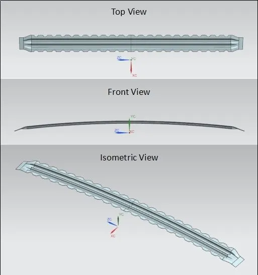
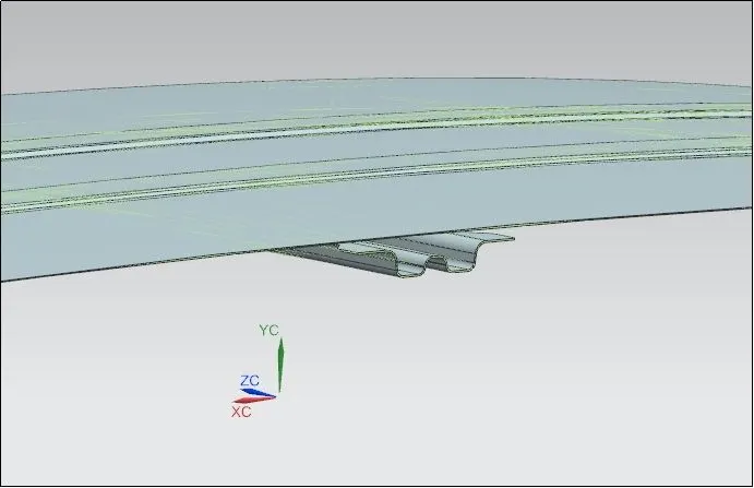
4. Center Reinforcement Rail:
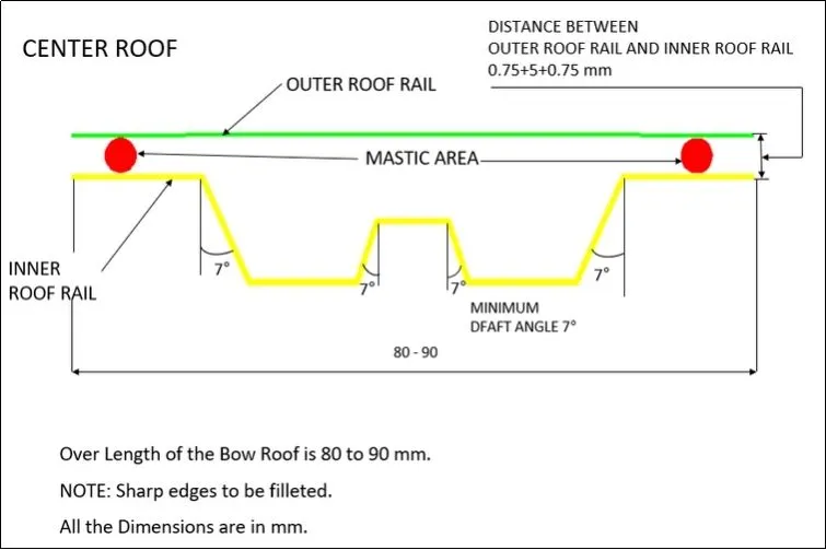
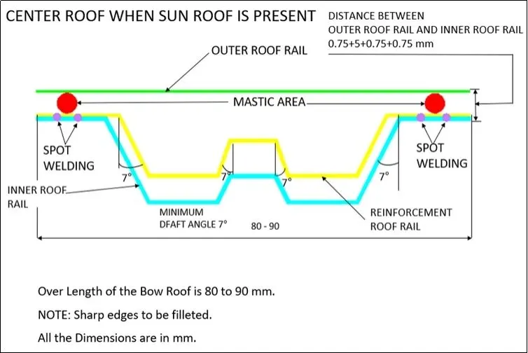
The center reinforcement rail provides additional support to the roof structure. This rail runs along the center of the roof and is designed to resist bending and twisting forces that occur during normal driving, as well as during sudden braking and impact situations. In the sunroof, the center reinforcement rail may be integrated with other roof structural components, such as roof pillars and bow roof side rails, to create a more rigid roof structure that provides better crash protection and improved handling and stability.
Center Reinforcement Rail Master Section:
Design Points:
- The centre roof rail is positioned almost 45% or roof middle to provide additional support. In sun roof panels, the centre roof rail is positioned closer to the that and it will be integrated with the bow roof for extra support.
Various views:
Sectional View:
5. Bow Roof Rail:
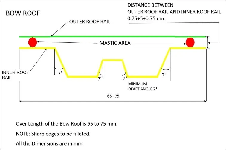
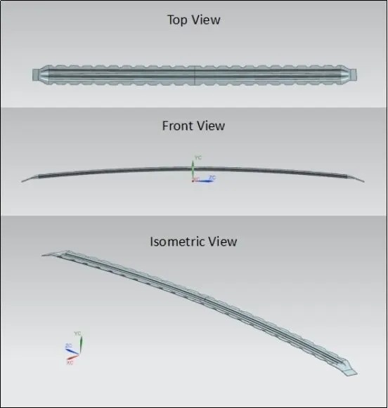
The bow roof rail is a structural component that provides additional support and stability to the roof structure. The bow roof rail is typically located in the gaps of the other roof rail and is designed like inverted hat shaped or "bow-shaped" cross section in the roof structure.
Bow Roof Master Section:
Design points:
- The bow roofs are similar to centre roof but quite shorter in width section.
- In a roof panel, multiple bow roofs can be fixed based on the vehicle type or length of the roof.
- These rails are positioned inside the flat surface of the roof and number of bow roofs are decided based on the required structural stability needed for he roof.
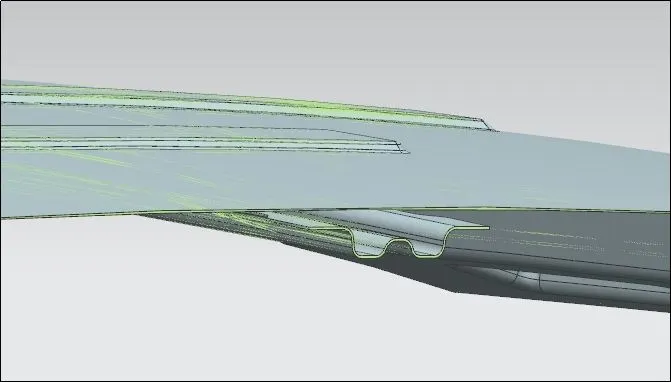
Various views of Bow Roof-1:
Sectional View of Bow Roof-1:
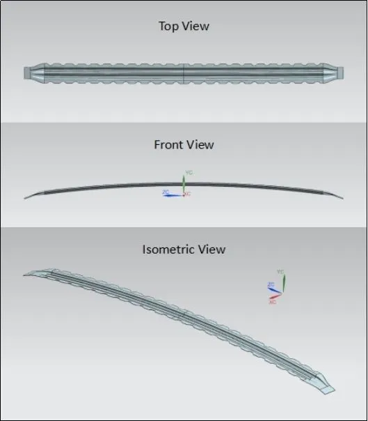
Various views of Bow Roof-2:
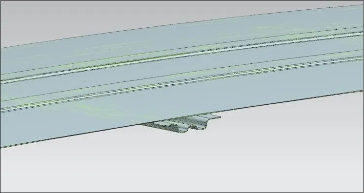
Sectional View of Bow Roof-2:
Calculations:
1. Heat DistortionPrediction:
Heat distortion is temperature limit above which material cannot be used for structural application. This study is useful to find the where the material starts to soften when exposed to a fixed load at elevated temperature. In order to avoid the bending, damage to the roof based on the heat distortion temperature. This study will provide the which position of the bow roof give enough strengthen to roof design.
Formula: W = [1.73 * 10-3 * L] + [1.85 * 10-8 * (R2 / t) + [1.10 * 10-3 * l] - 2.68
where, L = Roof Length in X-Direction [mm] (Roof dimension in 0-Y)
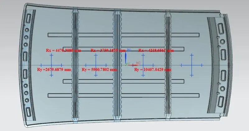
R = Roof curvature → R = 2 (Rx*Ry) / (Rx+Ry)
Rx = X curvature; Ry = Y curvature
t = Roof plate thickness [mm]
l = Bow Roof Span [mm]
Judgement Condition: OK if W < 2.7
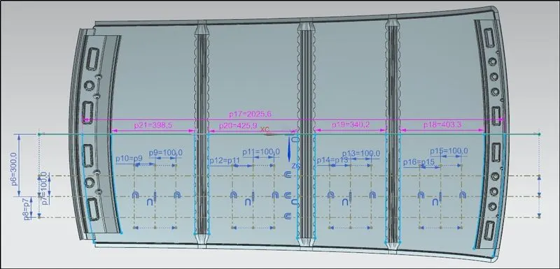
Various Measurements required to calculate:
1. Length between each reinforcement roof rails:
2. Roof Curvature Measurement:
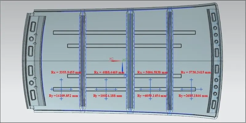
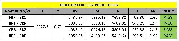
All the sections of the roof panel passes the judgement condition of the Heat Distortion. So the roof panel can withstand the temperature heat and won’t get damaged.
2. Snow Load CriteriaPrediction:
Snow load criteria study is used to check the durability of the roof to withstand the snow fall on the roof and regain its original shape without any permanent deformation after load being removed.
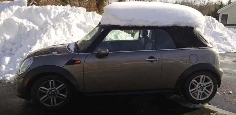
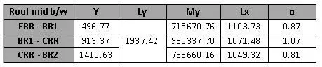
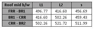
Formula: Qr = [Iy * t2] / [α * s * [(Rx + Ry)/2]2 * 10-8]
where, α = My x Lx2 x 10-12 , My = Y(Ly-Y)
t = Roof plate thickness [mm]
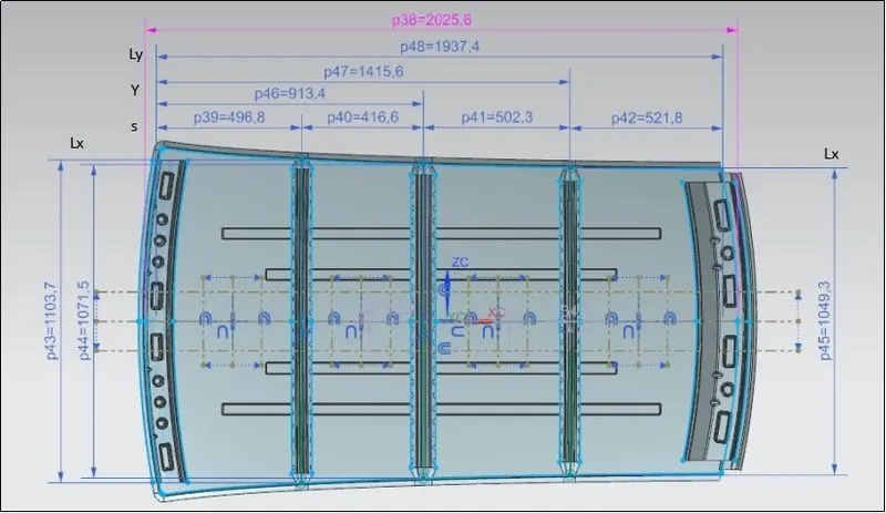
Ly = Distance between the front and rear roof Rails on the Vehicle along with 0Y[mm]
[Length of Roof panel with the center point between Roof rail Front /Rear as the front and
rear reference point]
Lx = Distance between the Left and Right end of the roof on the Roof BOW [mm]
[The width of the roof panel is exposed on the surface]
Y = Distance front Front Roof Rail to Roof BOW[mm]
s = Distance for which Roof BOW bears divided load [mm] → s = L1/2 + L2/2
Iy = Geometrical moment of inertia of Roof BOW (Y cross-section )[mm4]
Rx = Lateral direction curvature radius of roof panel Y cross-section on Roof BOW [mm]
[Roof panel curvature Radius of the Length Lx in Front view]
Ry = Longitudinal Direction curvature radius of the Roof panel X cross-section on Roof
BOW [mm]
[Roof panel X curvature radius of length s in Side view]
Judgement Condition: OK if Qr > 3.1
1. Various Measurements required to calculate:
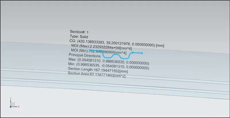
2. Sectional Modulus for roof rails:
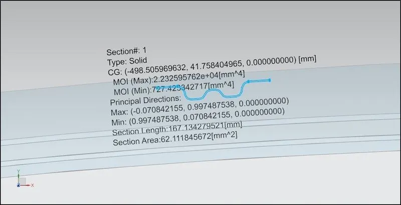
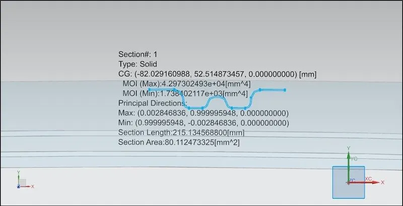
Section modulus is a geometric property for a given cross-section used in the design of beams or flexural members. Other geometric properties used in design include area for tension, radius of gyration for compression, and moment of inertia for stiffness. Any relationship between these properties is highly dependent on the shape of the object.
Definition:
Section modulus is defined as the ratio moment of inertia of a section about the neutral axis to the distance of the outermost layer from the neutral axis.It is denoted by the symbol Z or S. Hence mathematically section modulus is given by,
S = I/ymax OR S = I/c
where I - Moment of Inertia about neutral axis
y - Distance from the neutral axis to any given fiber
y → ymax or c - Distance of the outermost layer from neutral axis.
1. Bow roof rail 1:
2. Centre roof rail:
3. Bow roof rail 2:
3. Curvature radius of roof panel:

Here, the roof panel fails to withstand in snow load criteria between centre roof rail and bow roof-2 which can be overcome with the help of reinforcement rails. In this case, both the centre roof rail and bow roof-2 support the roof panel to withstand the deformation. Usually on large seating capacity vehicles, the number of bow roof are higher than the usual ones, which are positioned and used to support the roof panel from these kind of deformations.
Draft analysis:
The draft analysis technique is used to analyze whether the designed part model is manufacturable based on the draft angle condition applied on it. The part should get easily removed from the panel dies (in case of Sheet metal part) or Mold (in case of plastic). As no parts can be ejected from the tool if it is having a straight 90-degree profile from its base surface. A small draft angle is provided to each and every area of the component in order to get easy removal of the component from the tool. Hence it is required to provide a direction in which components should eject easily from the tool.
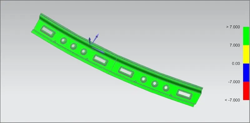
Once the design was ready, the inner panel of the hood was analyzed for manufacturability. Draft analysis is done for the minimum draft angle of 7 degrees. Here the draft analysis for various part shows that the die can come out of the cavity without any interruption.
Draft Analysis for various parts:
1. Roof Panel:
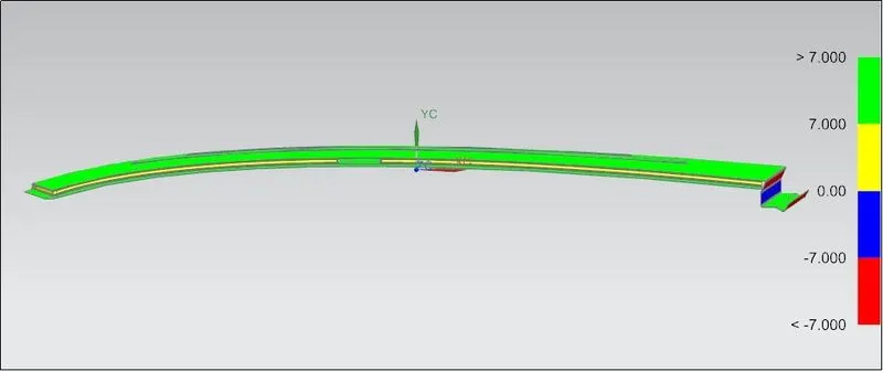
Here, in the rear portion the negative draft is shown due to the sheet metal bending design for the opening angle trajectory for back door. The red, blue and the rest tail portion are manufactured by bending operation. So, there is no difficulty to produce the part.
2. Front Reinforcement Roof Rail:
3. Rear Reinforcement Roof Rail:
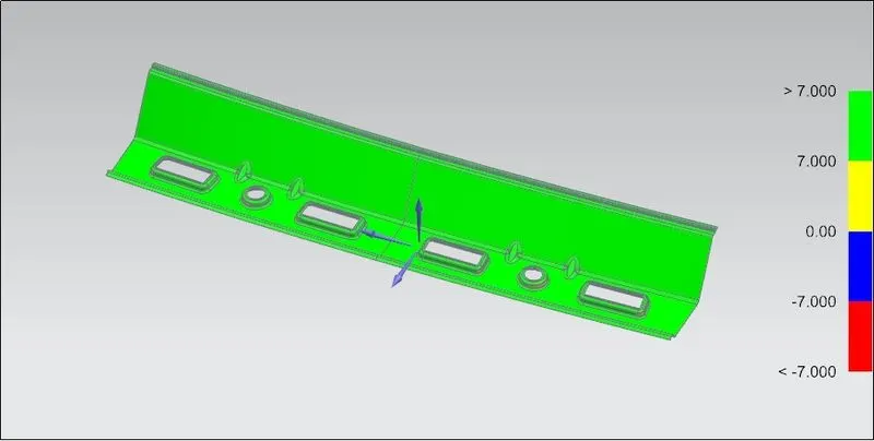
4. Centre Reinforcement Roof Rail:
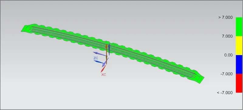
5. Bow Reinforcement Roof Rail-1:
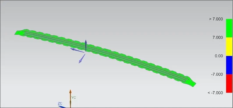
6. Bow Reinforcement Roof Rail-2:
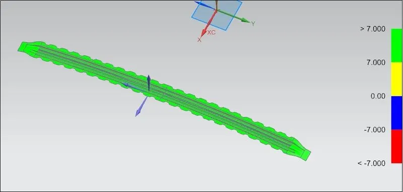
Manufacturing process involved in Hood Assembly:
1. Deep Drawing:
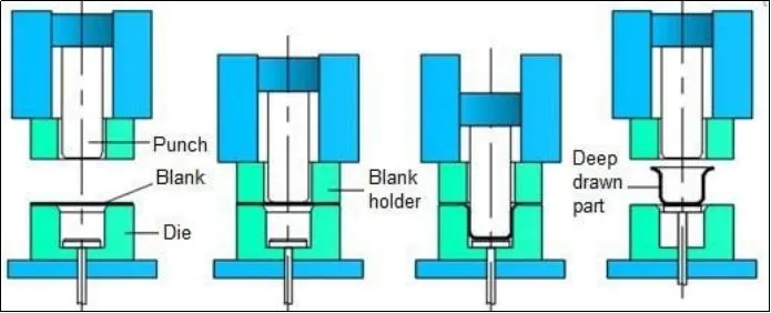
Deep drawing is a manufacturing process that is widely used in the formation of flat sheet metal into cup-like or box-like structures and even more complex contours. However, as complexity increases, manufacturing problems increase rapidly. It is better to design the shape of a deep drawing to be as simple as possible. Automobile parts, such as panels and gas tanks, are among a few of the items manufactured by sheet metal deep drawing.
Deep drawing is a sheet metal forming process with a punch and die that involves intricate material flow and force distributions. The punch and die setup is most similar to a sheet metal cutting operation, such as punching or blanking. Two main factors will cause the punch in a deep drawing to draw the metal into the die cavity, rather than shearing it. One major factor in the deep drawing is the die corner radius and the punch corner radius. When cutting sheet metal, the punch and die edges do not have a radius. Sharp corners on the punch and die cause it to cut. The force distribution will be altered by a radius on an edge, causing the metal to flow across the radius and into the die cavity. The amount of clearance is another important component that contributes to the punch drawing the sheet metal rather than cutting it. In the cutting process, clearance is typically between 3% and 8% of the thickness of the sheet metal. Deep drawing manufacturing often has clearance values between 107% and 115% of sheet thickness, which is larger than the thickness of the sheet.
2. Bending:
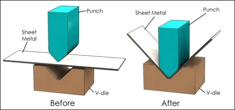
Bending is a manufacturing process mostly used in sheet metal that produces various shapes like V-shape, U-shape, or channel shape along a straight axis in ductile materials. Commonly used equipment for bending process are pan brakes, brake presses, and other specialized machine presses.
The bending process followed in press brake forming, a work piece is positioned over the die block and the die block presses the sheet to form a shape. Usually bending has to overcome both tensile stresses and compressive stresses. When bending is done, the residual stresses cause the material to spring back towards its original position, so the sheet must be over-bent to achieve the proper bend angle. The amount of spring back is dependent on the material, and the type of forming. When sheet metal is bent, it stretches in length. The bend deduction is the amount the sheet metal will stretch when bent as measured from the outside edges of the bend. The bend radius refers to the inside radius. The formed bend radius is dependent upon the dies used, the material properties, and the material thickness.
3. Embossing:
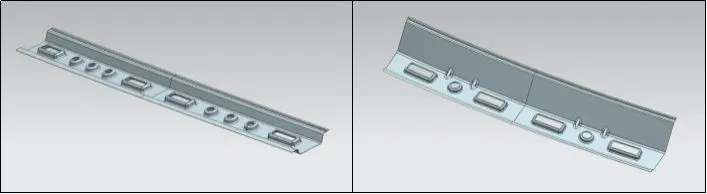
Sheet metal embossing is a stamping process for producing raised or sunken designs or relief in sheet metal. This process can be made through matched male and female roller dies, or by passing a sheet or a strip of metal between rolls of the desired pattern. It is often combined with Foil Stamping to create a shiny, 3D effect. The metal sheet embossing operation is commonly accomplished with a combination of heat and pressure on the sheet metal, depending on the types of embossing is required. Theoretically, with any of these procedures, the metal thickness is changed in its composition.
4. Blanking & Piercing:
Blanking and piercing are shearing processes in which a punch and die are used to produce parts from sheet metal. Blanking produces the outside features of the component, while piercing produces internal holes or shapes.
Roof crush test:
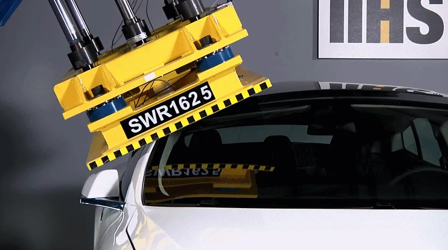
Roof crush test is the done by the IIHS (Insurance Institute of Highway Safety). After analysing many accidents, the IIHS has then fixed some regulations and procedures that how to perform the roof crush test and gives the rating based up on the test results.
To perform the test, they consider two points for giving the rating are:
- How fast the car can reform to its original shape after the roll over
- How deep is the protrusion after the roll over
The goal of the roof crush test is to minimize the protrusion into the occupant compartment, so that the seat belts and air bags can do their job in protecting the occupant on accidents.
Testing Procedure:
Before starting the testing, need to ensure that all the windows are all locked and the glass shield are up, and fix the vehicle frame on the hard lever horizontally.
The test is conducted on the either side of the roof structure, the front left or front right or both in a single test. The rigid plate which is fixed on the Roof Crush Test System should not move faster than 0.5inches per second and the force acting should not be less than 1.5 times the unloaded vehicle weight.
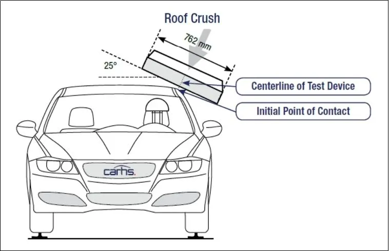
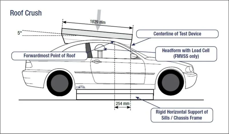
Rollover accidents of a car are the most occurring accidents that we see in our daily lives. The passengers experience major injuries like neck, head and spine injuries. So, to reduce the injuries of a passenger from major fatalities it is important to provide safety in the car. Though safety is provided by seat belts and airbags during accidents, the passenger must have sufficient space for survival in the car during accidents. The roof of the car must have high strength to resist the crush force to avail the passenger some space for survival.
Conclusion:
The roof panel is designed along with the reinforcement rails according to given master section and design considerations. The heat distortion and the snow load calculations are made and found the pain points of the roof panel. Based on these pain points the bow roof have designed and positioned on the roof outer panel. Additionally, embossed faces are provided to enhance the strength of the roof panel and also discussed about the manufacturability methods and the roof crush test.