Roof Design
ROOF DESING:
OBJECTIVE:
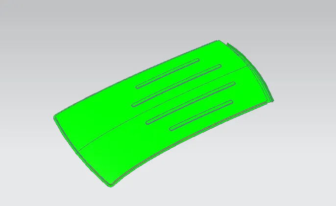
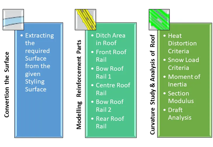
*Main objective of the project is to create the Roof Sheetmetal design in NX cad, and also designing Front roof rail, rear roof rail, bow roof front, bow roof rear, center roof rail and Reinforcement are creating to build the strong roof.
*Do curvature study on Roof and performance calculations for Heat distortion and Snow load criteria to determine the position of the Bow roofs.
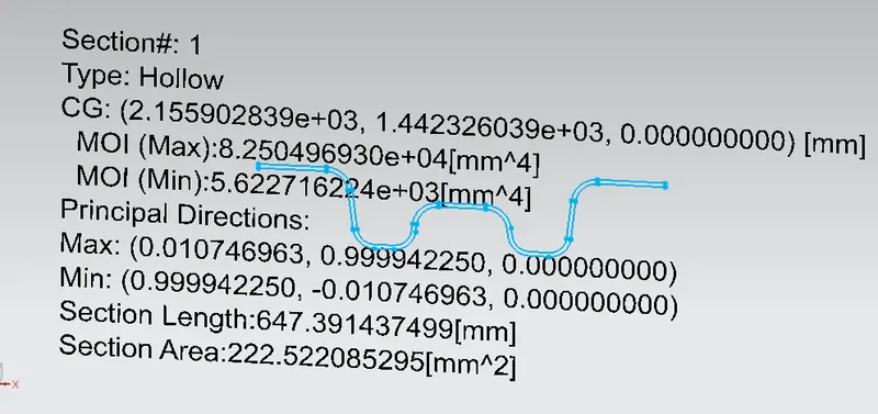
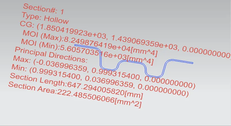
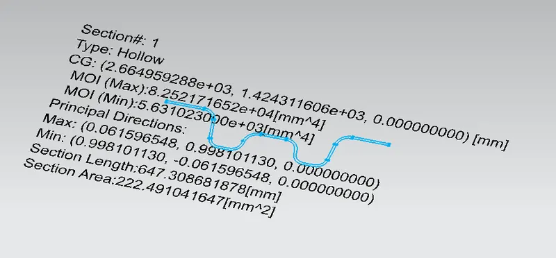
*Finding the moment of inertia and section modulus for Bow-roofs and center roof rail.
*And, also finding the Draft Analysis of each part.
INTRODUCTION:
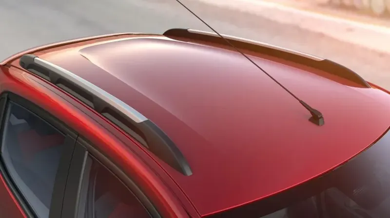
An automobile roof or car top is the portion of an automobile that sits above the passenger compartment, protecting the vehicle occupants from sun, wind, rain, and other external elements. When it is seeing from outside of the car, it is just closing the top portion. But in design point of view, it is hard to create the design. Because of you have to create no of support rails for enough strength to withstand the load. Bow roofs are primarily fixed in flatter region to enhance strength. Front roof and rear roof rails are fixed to the ditch area using spot weld operation. But front, rear bow roof and center roof rails are fixed to roof using mastic sealants. We don’t want so much gap between roof rails and bow roof area. So, we reducing the NVH issues.
METHODOLOGY
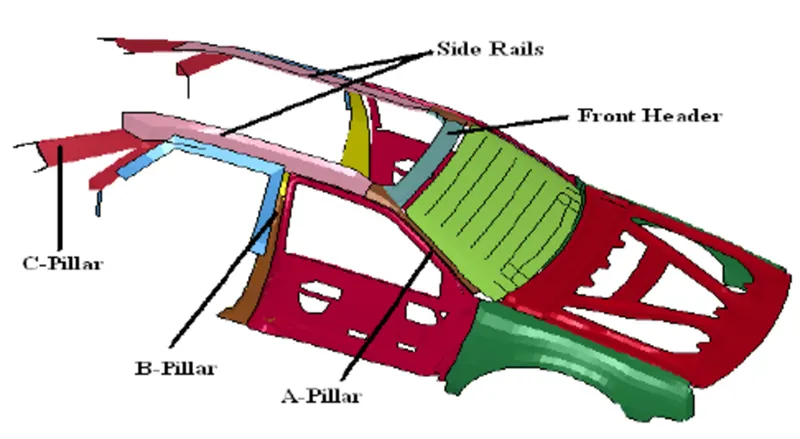
We get the model of the roof of the from the styling team. Then we will have to do all the engineering work. We create the ditch area for the roof and also the roof bows and roof rails for the roof which would we designed by us considering all the safety norms and regulations.
ROOF CRUSH TEST:
OVERVIEW OF THE TEST:
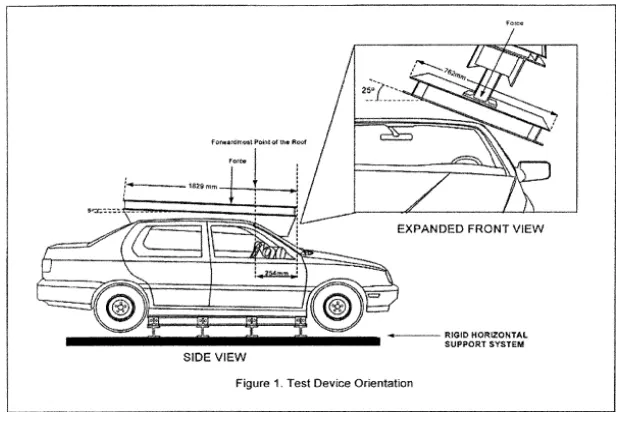
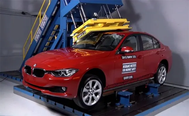
Roof strength evaluations consist of a quasi-static test conducted on a vehicle’s roof in a manner similar to tests used to judge compliance with Federal Motor Vehicle Safety Standard 216 (Office of the Federal Register, 2009). The main differences between the procedure specified by the Insurance Institute for Highway Safety (IIHS) and that specified by the U.S. federal government are that the IIHS procedure are,
Specifies testing one side of a vehicle’s roof
Does not include a headroom criterion
Specifies testing to a given displacement instead of a given force level
Specifies setting the vehicle’s pitch angle during testing based on the measured on-road pitch angle.
An overall rating is assigned based on the peak strength-to-weight ratio (SWR) measured within 127 mm of plate displacement.
CURB WEIGHT MEASUREMENT:
Curb weight values used for calculating the SWR are based on IIHS measurements of a vehicle, not the manufacturer’s specified curb weight.
Vehicle curb weight is measured with full fluid levels using scales manufactured by Longacre Racing Products (Computer scales DX series 72634).
TEST VEHICLE SELECTION:
For information on how we select vehicles for our crash test programs, including how we define typically equipped vehicles, see Test Vehicle Selection. Whenever possible, the vehicle acquired for testing is the same vehicle used for the curb weight measurement.
At times, it is necessary to test a vehicle that does not meet the IIHS definition of a typically equipped vehicle, and the curb weight measurement is applied from another vehicle that does meet the definition. In these cases, the test vehicle does not differ from our typically equipped vehicle definition in any way that might influence the roof strength.
Once the test vehicle has been acquired, either the driver or passenger side of the vehicle is selected for testing. For most vehicles, the test side is chosen at random. However, for roof designs that appear asymmetrical, engineering judgment is used to select the side of the roof that may result in a lower peak force.
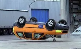
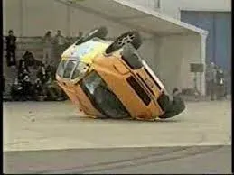
Car Rollover Test:
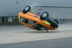
The rollover test is conducted because a rollover is a type of vehicle crash in which a vehicle tips over onto its side or roof. Rollovers have a higher fatality rate than other types of vehicle collisions.
Vehicle rollovers are divided into two categories: tripped and untripped. Tripped rollovers are caused by forces from an external object, such as a curb or a collision with another vehicle. Untripped crashes are the result of steering input, speed, and friction with the ground.
Vehicles which have a higher center of gravity like SUVs or Small Trucks are more prone to rollover. Rollover accidents typically involve a singular vehicle that loses control due to icy or snowy road conditions, soft road shoulders, uneven ground, collision with curbs or guardrails after a vehicle has lost traction, or hitting an obstacle while driving.
During a rollover accident, the regional body distribution of injuries normally affects five main areas: head and neck, thorax, abdomen, upper limbs, and lower limbs. The majority of rollover crash victims sustain multiple injuries throughout these regions with the head and neck being the most vulnerable area. Some of the most common rollover injuries include traumatic brain injury, spinal cord injury, broken bones, cuts, scrapes, and bruises. These injuries are caused by slamming into another vehicle or obstacle, impact with unsecured cargo, contact with broken glass or torn metal, or being tossed within the vehicle or ejected from the vehicle.
Manufacturing Techniques:
By outer board machining process, bar-shaped assembly, ring-shaped component processing, and roof cant rail processing technology formed respectively.
Outside plate process: the first step, open the straight snips plate: first select the applicable cold coiling specification, and cold coiling is opened flat; Then according to the production material specification, will open cold coiling after the flat and is cut into the iron plate of the corresponding size; Finally the iron plate after shear is cleaned to iron filings; The first step, oil pressure, punch press: the first iron plate is extended; Secondly to its trimming and punching; Then to its flanging and punching; Finally, after punching completes, it is carried out to the operation of side folding; Completed the making of the outside plate.
Bar-shaped assembly and ring-shaped component process: the first step, blanking, stamps out an iron plate with the outline blank of many roof cant rails, a ring-shaped component, and a bar-shaped assembly; the Second step, carries out annular punching to ring-shaped component; Bar shaped assembly and roof cant rail are carried out to bar-shaped punching.
Car roof anabolic process: the first step, is by a plurality of M6 nuts of a side spot welding of the ring-shaped component; By two M6 nuts of the bar-shaped assembly two ends spot welding; the Second step, spots weld bar shaped assembly the opposite side of the corresponding nut of the ring-shaped component; And circular groups and the punching of bar-shaped assembly are aimed at; The 3rd step, is welded to ring-shaped component the inner side of the outside plate; The 4th step, spots weld roof cant rail the inner side of the outside plate; Finally car roof integral body is carried out to sanding thorn and ending.
Procedure:
Styling Surface to Extracted Surface:
The styling team has provided the solid dump outer panel from that we are extracting the surface to model the necessary reinforcements like Ditch area, Front Roof Rail, Bow Roof Rails, Centre Roof, and Rear Roof Rail.
Design a Ditch Area for Outer Roof Panel:
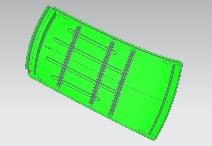
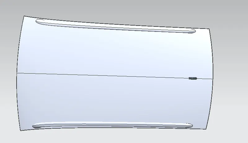
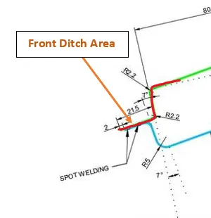
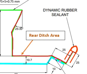
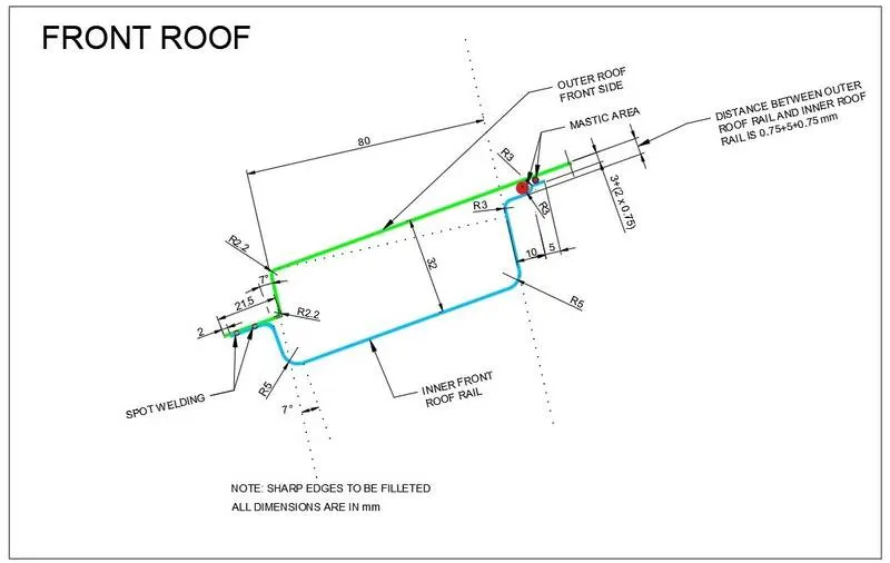
The styling team provided the master section for the roof ditch area, front roof rail, and rear roof rail as per the parameter of visibility criteria, headroom clearance, and other important parameter dimensions like fitment of the windshield, sealant rubber, etc. All these data are well calculated in the planning stage to design the peripheral component accordingly. Thus, here designing is done just to replicate those input data considering engineering parameters that should be feasible for manufacturing. Master section of the front and rear section. The Ditch Area is the extended portion of the main Roof concealed by other BiW panels. The rail supports of the roof are attached to the Ditch Area using Spot welds since it is not a styling surface and remains concealed. Headroom Clearance, visibility criteria, and clearance for Windshield and Back door are some of the factors to be considered while designing the Ditch Area. It is given a thickness of 0.75 mm.
Front Ditch Area:
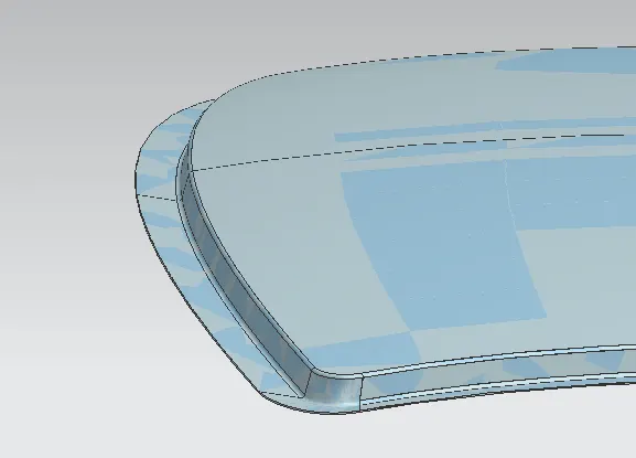
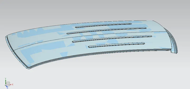
From the dump solid part class, A surface is extracted and the ditch area is developed considering the parameter specified in the following master section.
The flange of around 15mm was created with the law extension command, corner relief at rear flanges, and a positive draft of more than 3 degrees considering the drawing operation process. The overall thickness of sheet metal considers 0.75mm throughout.
Rear Ditch Area:
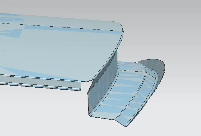
The surface is offset from the outer panel to form the ditch area and with the law extension command, corner relief at rear flanges, and positive draft in the required degree considering for the drawing operation process. The overall thickness of sheet metal for the outer panel consider 0.75mm throughout.
Design of Front Roof Rail:
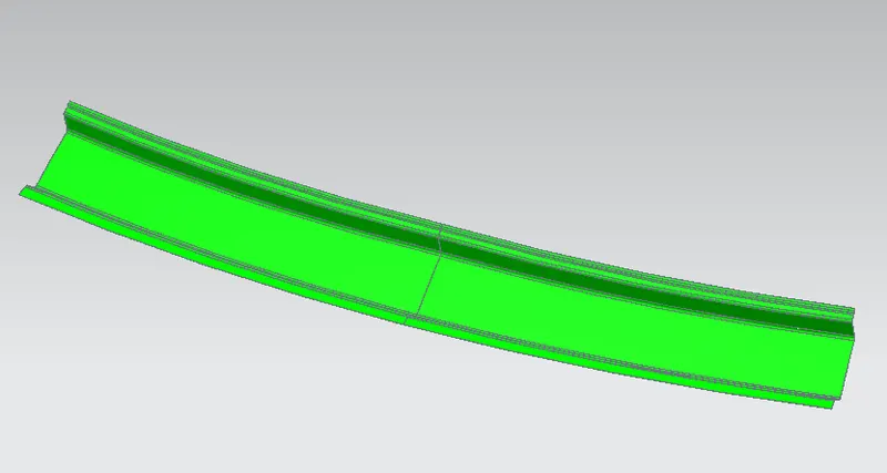
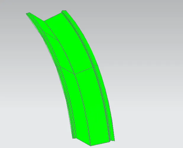
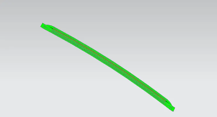
The front rail underpins the rooftop external shell at the front end. It is mounted with support rooftop rail fortification on the two closures. The rails are furnished with embosses to improve the strength over the length and the rail is associated with the external board utilizing mastic sealants on one side and the other joinery is spot welded. It is the support that is joined with the Wind Shield Glass, Body Side Outer, and inner panels. It is usually made from Body Side Outer scrap and therefore the thickness of the rail is 0.75 mm. A draft angle of 3-5 degrees is provided keeping in mind the deep-drawing operation. The Wind Shield end flange is the exact offset of the roof surface. The bottommost flange is decided after taking into consideration the visibility criteria and the Headroom Clearance of the passenger. Spot Welds are applied at the Windshield end of the rail and the other end is joined with the roof using Mastic Sealants which also contributes to increased strength.
Design of Rear Roof Rail:
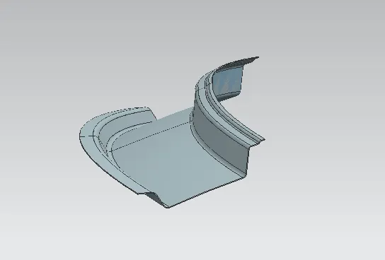
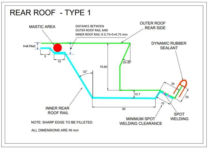
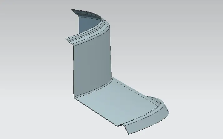
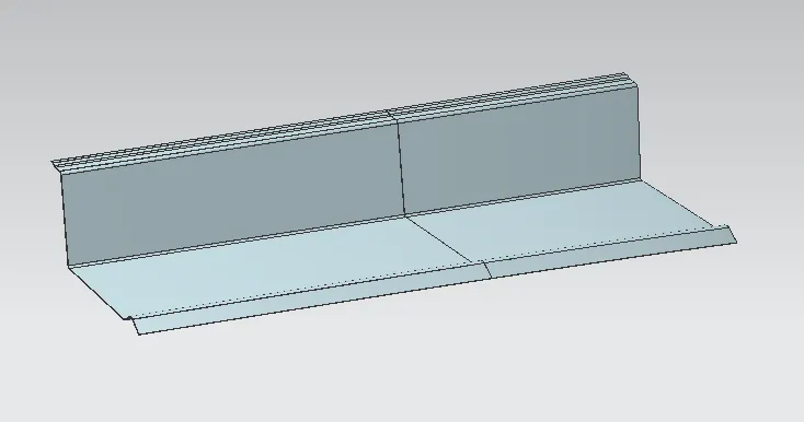
It is the support that is joined to the Back Door and the Body Side Outer and inner panels. It is also usually made from Body Side Outer scrap and therefore the thickness of the rail is 0.65 mm. Similar to the Front Roof Rail design, we have to take into consideration the rear Headroom Clearance and the rear visibility criteria while designing the Rear Roof Rail. Inputs are taken from the rear master section. It is the support that is joined to the Back Door, the Body Side Outer, and the inner panels. It is also usually made from Body Side Outer scrap and therefore the thickness of the rail is 0.75 mm. Similar to the Front Roof Rail design, we have to take into consideration the rear Headroom Clearance and the rear visibility criteria while designing the Rear Roof Rail. Inputs from the backdoor design are also taken to accommodate the required clearance. Spot Welds are applied at the Back door end of the rail and the other end is joined with the roof using Mastic Sealants.
Design of Bow Roof Rail:
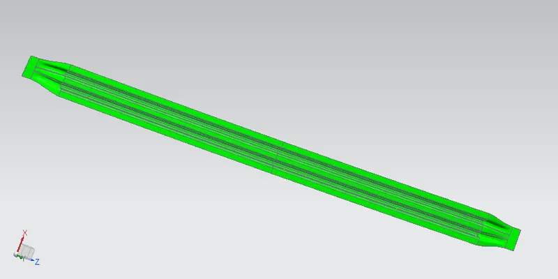
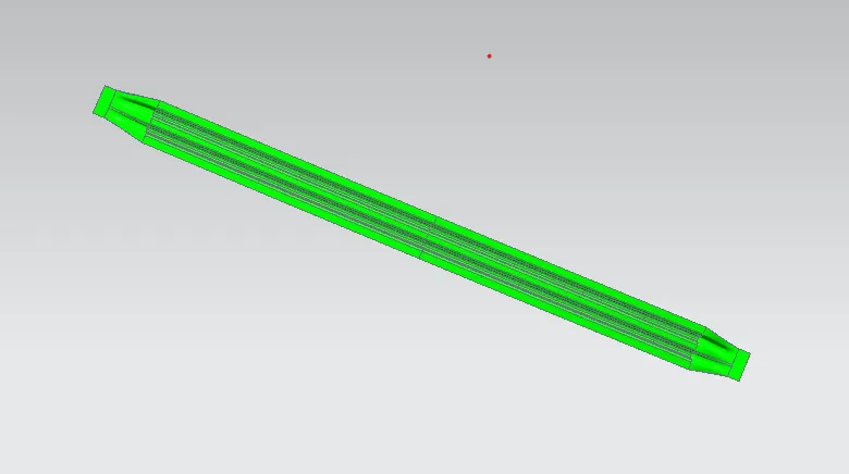
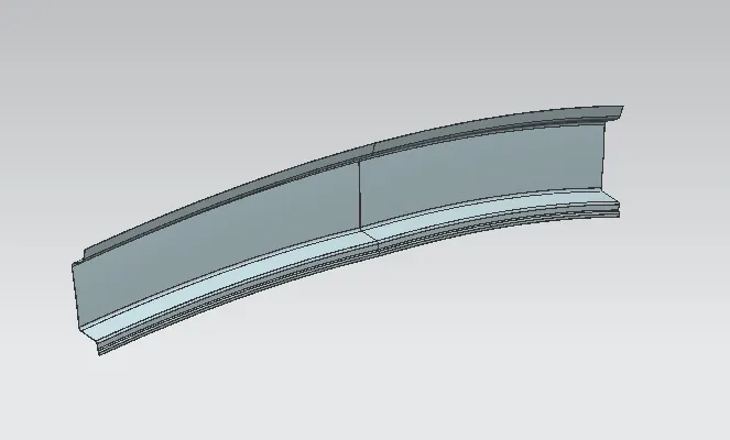
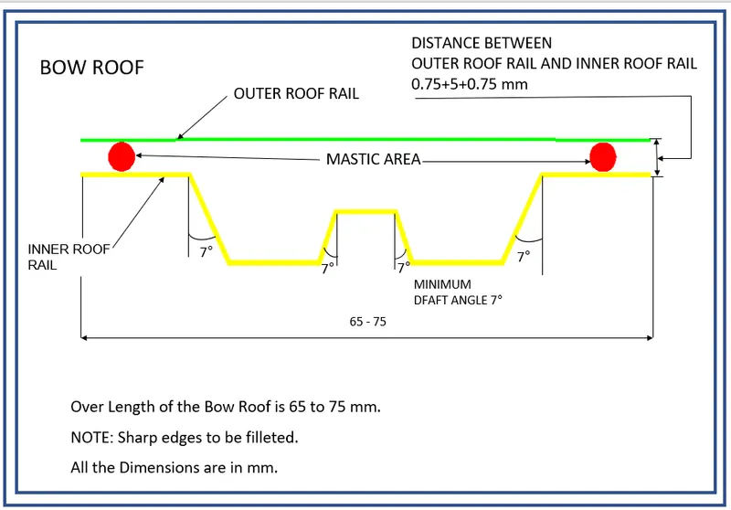
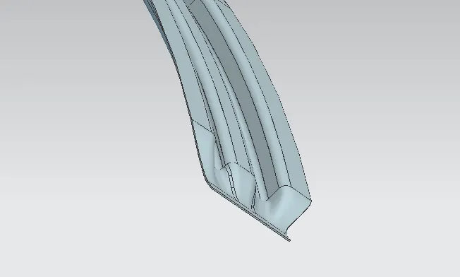
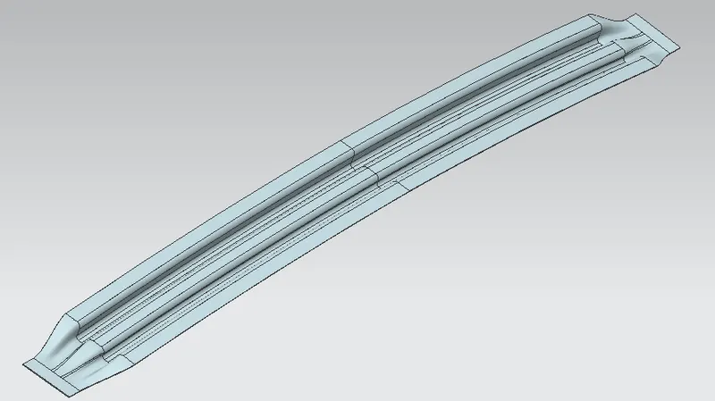
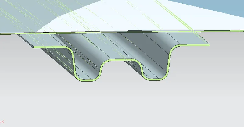
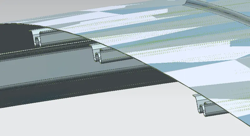
The Bow roofs are given to improve the torsional stiffness and load-bearing capacity of the roof structure. The number of bow roofs provided will depend upon the overall dimensions of the roof. The longer the roof more the bow roofs are integrated into the BIW frame They are attached to the outer panel using mastic sealants. Each mastic point will have up to 80 mm circular effective area. The positioning of bow roofs is done based on a curvature study. The heat distortion criteria and snow load criteria are checked to analyze the position of the bows in various conditions. The thickness of the Bow Roof is 0.75 mm and also mastic area has been created. Two Bow roofs are required for this project so we will have to make 2 bow roofs with the same master section properties.
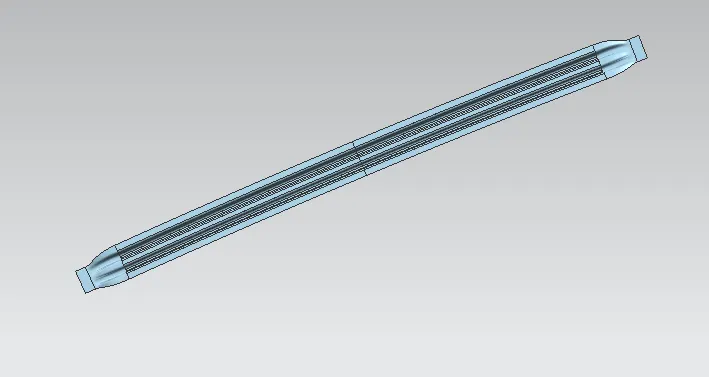
Design of Center Roof Rail:
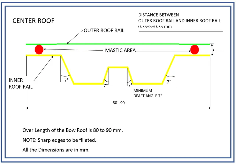
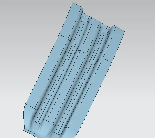
Centre roof rail is provided to effectively support the flat area of the roof as it is more susceptible to failure under the action of the load. Usually, the center reinforcement roof rail will be placed at the center of the roof connecting the B pillar support structure which results in added support in the roll-over test. The thickness of the center bow roof is 0.75 mm thickness.
Joining Process of the Reinforcements:
- Joining of the Outer Roof Panel and the Front Roof Rail is done by spot welding. The Front Ditch area and the front roof rail are spots welded as it is an easy and efficient process and the welding will be hidden under the windshield area so that it doesn't affect the aesthetic of the car. The same process is done for the joining of the Outer Roof Panel and the Rear Roof Rail, The Rear Ditch area and the Rear Roof Rail are spot welded and they are hidden by the installation of the back door.
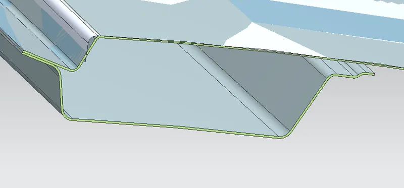
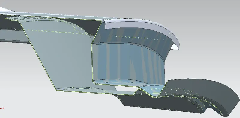
- Joining of the middle part of the Outer Roof Rail, Bow Roofs, and Center Roof Rails are done by the use of Mastics Sealants. Here we cant use Spot welding because it damages the A-Class area of the Roof. So, mastic sealant is used in this area. For the application of these Mastics, there must be a gap of at least 5mm between the Roof Outer Panel, Bow Roofs, and Center Roof Rail. The ends of the Bow Roofs and Center Roof Rails are joined by spot welding to the Side Ditch area of the Outer Roof Pan
INERTIA ANALYSIS:
CURVATURE STUDY ON THE ROOF:
HEAT DISTORTION:
The heat distortion study the plays an important role in Sheetmetal application. Heat distortion is temperature limit above which MATERIAL cannot be used for structural application. This study is useful to fin the where the material starts to soften when exposed to a fixed load at elevated temperature. In order to avoid the bending, damage to the roof based on the heat distortion temperature. This study will provide the which position of the bow roof give enough strengthen to roof.
Bow Roof Prediction Formula:
HEAT DISTORTION CRITERIA:
W = [1.73 x 10^(-3) x L] + [1.85 x 10^(-8) x (R^2)/2] + [1.10 x 10^(-3) x I]-2.68
Judgement Condition: OK<2.7>3.1
Where,
L= Roof Length in X- direction [mm](Roof Dimension in 0-Y)
R = Roof curvature
R = 2(RX*RY)/(RX+RY)
RX = X Curvature
RY = Y Curvature
t = Roof plate thickness [mm]
I = Bow roof span [mm]
Thickness for the Roof(t):
Roof Outer Panel, t= 0.75mm
Front Roof Rail, t = 0.75mm
Rear Roof Rail, t = 0.75mm
Bow Roof Rail Front, t = 0.75mm
Bow Roof Rail Rear, t = 0.75mm
Reinforcement roof rail, t = 0.75mm
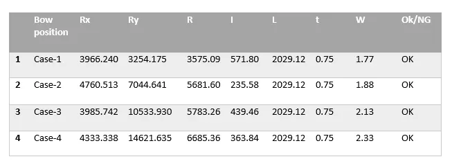
in this calculation of the all cases the value is in ok condition.
SNOW LOAD:
Snow load criteria study is used to check the durability of the roof to withstand the snow fall on the roof and reflex it is original shape without any permanent deformation after load being removed.
SNOW LOAD CRITERIA:
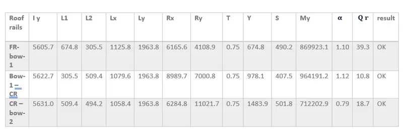
Qr = [IY x t2] / [α x s x [(RX + RY)/2]2 x 10-8]
Where,
α = My x LX2 x10-12, My = Y(Ly–Y)
Judgement condition = Qr > 3.1
250 < s < 380
t = Roof plate thickness[mm]
LY = Distance between the front and rear roof rails on the vehicle along with 0Y[MM],
Length of roof panel with the center point between roof rails front/ rear as the front and rear reference point.
LX= Distance between the left and right end of the roof on the roof bow[mm],
With of the roof panel exposed on the surface.
Y = Distance between Front roof rails to roof bow [mm],
s = Distance for which roof bow bears divided load [mm],
s = L1/2 + L2/2
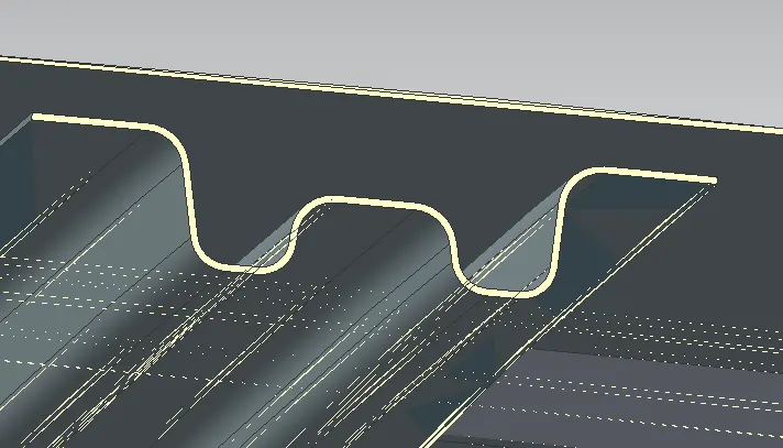
Iy = Geometrical moment of inertia of roof bow (Y cross – section) [mm4],
RX = Lateral direction curvature radius of roof panel Y cross section on roof bow [mm4],
Roof panel curvature radius of the length LX in front view.
RY = Longitudinal direction curvature radius of the roof panel X cross section on roof bow[mm4],
Roof panel X curvature radius of length s in side view.
RX & RY (X & Y Curvature):
At 0-Y axis on perpendicular plane to roof. Draw 100mm lines offset to either side of the of 0Y axis line. Now center lines are drawn between each adjacent roof rail respective. Intersection points are marked on the sketch. Make all the geometry in construction lines except points.
Project the intersection points in the sketch are projected to roof surface.
Join the project points using arc curve and measure the radius value using minimum radius comment.
DRAFT ANALYSIS: