Roof Design
Roof Design
Introduction
Roof is that component in a car covers the top portion of the car and protects the passengers from outside atmospheric conditions such as heat from the sun in hot countries and snow in winter countries and also rain and other external debri.This serves the purpose of safety in case of topple over of a car.The roof is connected to the A pillar at the front,B Pillar at the middle and C pillar at the rear in case of a normal sedan cars.Roof can have different designs depending upon the design of the car.Some cars have a sunroof and some dont.
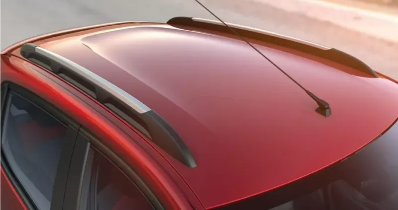
The roof is made out of sheet meta component and is a part that is exposed to the customer side.So the surfaces are to be extremely well in visibility or should be a class A surface.This Class A surface data will be provided by the Class A designer in an Automotive engineer and the BIW engineers has to design the internal features of the surface input.
Objective
In this project the roof of a car is to be designed from the Class A data as an input.The roof has other supporting members such as front roof rail,rear roof rail ,centre roof rail,Bow roof etc.These supports are actually connected to the A pilla,B pillar and C pillar etc.The roof is spot welded at particular locations and also mastics are attached at particular sections to give strength and also reduce the NVH of the car as a whole.
The roof Surface data is taken as the input and Roof outer panel is to be modeled as per the master section given.Master section is the centreline section of the roof of the car and is predetermined by engineers or is taken from a previous car version if it is a facelift.As per the master section the roof outer panel is to be modeled in Software.Here we will be using software NX CAD and Catia for designing the Roof components.
Other components such as Front roof rail,rear roof rail,Centre roof rail and Bow roof etc are to be designed as per the master section provided.
Methodology
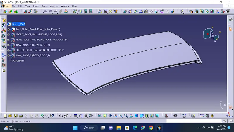
The roof is modeled in softwares NX cad and Catia.The roof is created as a an Assembly with parts
- Roof Outer Panel
- Front roof rail
- Centre Roof Rail
- Rear Roof Rail
- Bow roof etc
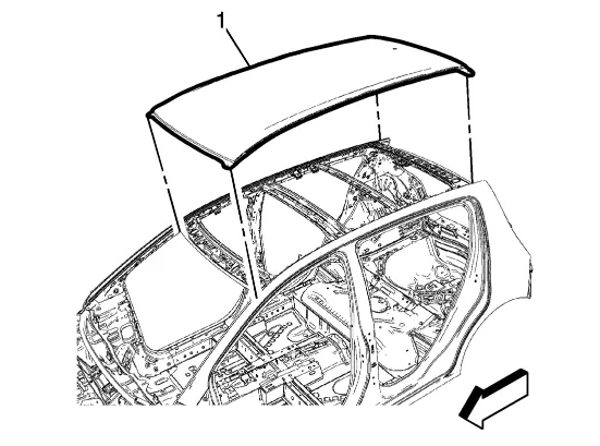
All these are mode from the surface data and as per the master section given in the question.
Roof Outer Panel
The roof outer panel is modeled in Catia and NX cad.The roof outer panel has a thiskness of 0.75 mm.
In catia The given surface is extracted and done an untrim operation to get rid of the rail holes that are present after extraction.
Then the Ditch area are designed using the sweep with respect to reference surface in Catia.Also the rear portion of the roof outer panel is also modeled using the Sweep with reference surface and in relation with the master section provided.
The roof outer panel is modeled as per the master section given in the challenge.
The tools that we have used in Catia are.
- Extract
- Surface untrim
- Join
- Split
- Edge Fillet
- Boundary
- Symmetry
- Extrapolate
- Thicken etc.
In a similar way the roof outer panel is modeled in NX cad and is shown below.
The tools used in NX Cad are.
- Wave Geometry Linker
- Untrim
- Extract Geometry
- Trim sheet
- Law extension
- Through curve mesh
- Offset curve in surface
- Bridge curve.
- Sew
- Edge fillet
- Thicken etc.
Front Roof Rail
The front roof rail supports the roof at the front of the car.It takes the load under stress conditions and acts as a stiffener for the roof outer panel at the front.This component connects to the A pilla of the car provides safety in a rollover and protects the passengers.Also this acts as a support for the windshield glass as windshield glass sits on the patch given by both Front roof rail and A pillar.
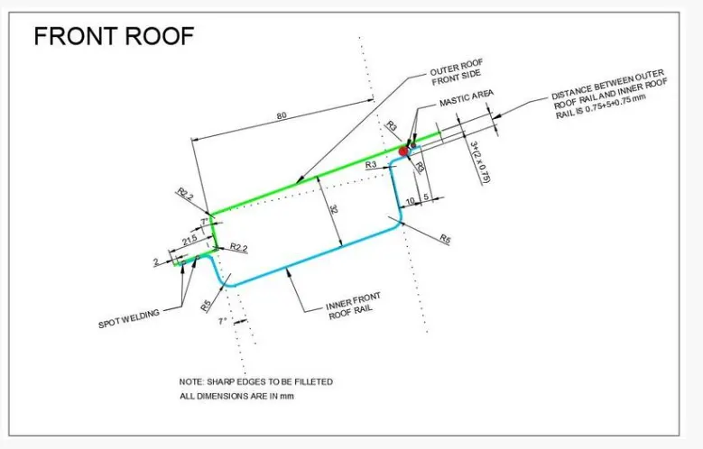
The front roof rail is modeled as per the master section in the image given below.
This is the same master section we have seen for modelling the front ditch area for the roof outer panel.On the front side of the front roof rail,it is spot welded onto the roof outer panel and the A pillar at the end.On the rear of the front roof rail it is attached to the roof outer panel by applying sealants known as mastics.This will hold the front roof rail rear and the roof outer panel together which increases the strength and also reducing the vibrations.
In Catia the front roof rail is modelled and is shown in the image below.
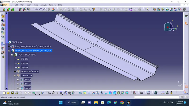
The tools used to model the front roof rail in Catia are.
- Paralle curve
- Copy-Paste as reference with link.
- offset surface
- Sweep-reference surface and draw direction.
- Split
- Trim
- Join
- Edge fillet
- Symmetry
- Thicken etc.
In Nx cad the front roof rail is modelled as given in the image below.
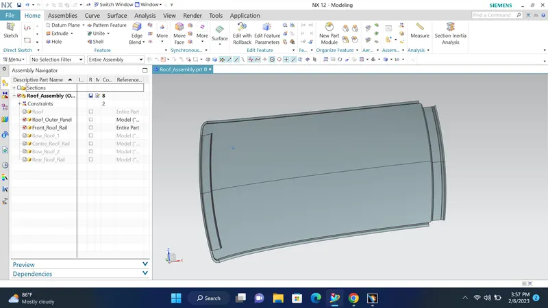
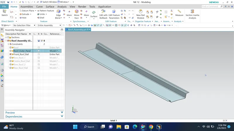
The tools that we have used to model the Front roof rail are as follows.
- Wave Geometry Linker
- Untrim
- Extract Geometry
- Trim sheet
- Law extension
- Through curve mesh
- Offset curve in surface
- Bridge curve.
- Sew
- Edge fillet
- Thicken etc.
Rear roof rail
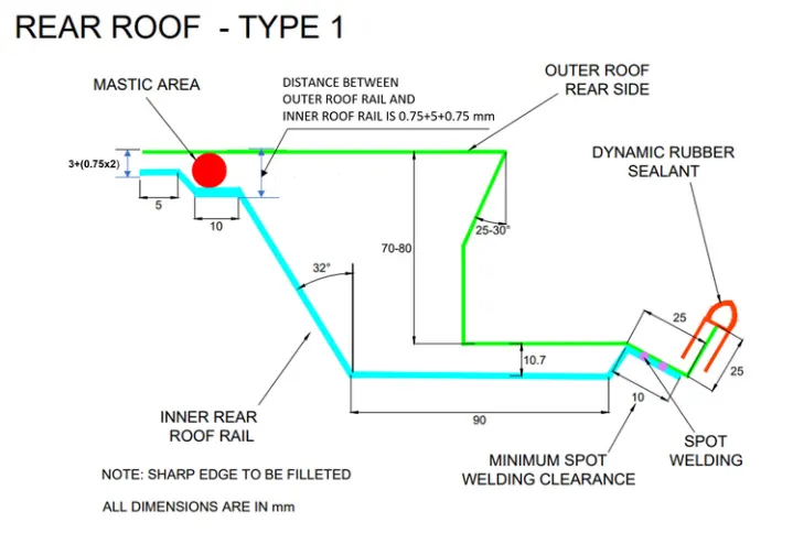
The rear roof rail supports the rear part of the roof and connects with the C pillar of the car.The rear of the rear roof rail is spot welded to the roof outer panel and the front of the rear roof rail is attached to the roof outer panel with mastic seals.The ends of the rear roof rail is spot welded to the C pillar.Rear roof rail supports the roof and takes the stresses at the rear of the car roof.The rear roof rail is modelled as per the master section in Catia and is shown in the image given below.
master section for rear roof rail.
Rear roof rail as modelled in Catia.
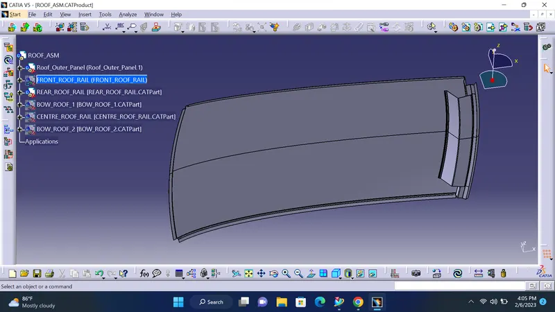
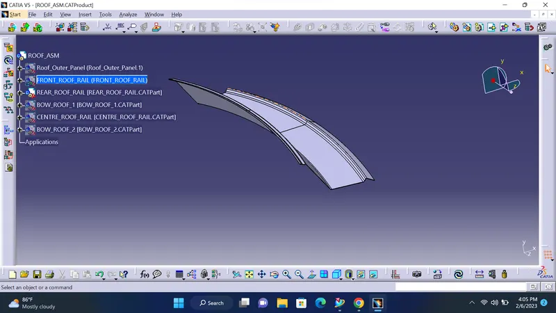
The main toos used in the rear roof rail in Catia are.
- Paralle curve
- Copy-Paste as reference with link.
- offset surface
- Sweep-reference surface and draw direction.
- Split
- Trim
- Join
- Edge fillet
- Symmetry
- Thicken etc.
Similarly the rear roof rail is modelled in the NX cad as per the master section and is shown in the image given below.
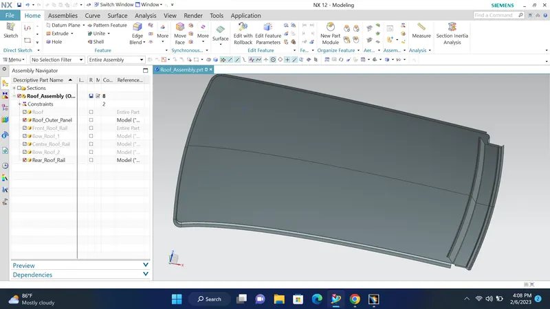
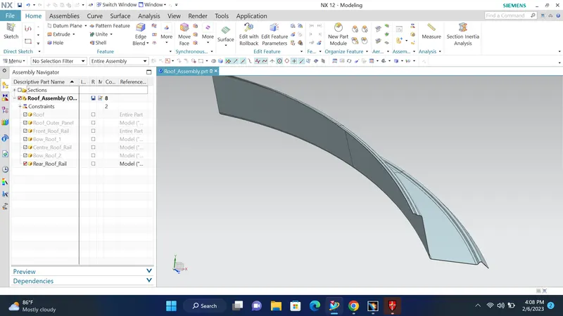
The toos used in rear roof rail in NX Cad are as follows.
- Wave Geometry Linker
- Untrim
- Extract Geometry
- Trim sheet
- Law extension
- Through curve mesh
- Offset curve in surface
- Bridge curve.
- Sew
- Edge fillet
- Thicken etc.
Centre Roof Rail.
The centre roof rail is that support member which is added at the central portion of the roof and connects the B pillar also.Both front flange and the rear flange are attached to the roof outer panel using mastic sealant.The ends of the centre roof rail is attacehd to the ditch area of the roof outer panel using spot welding.This is a major loading component of the car roof.The centre roof rail is modelled as per the master section given and is shown in the image given below.
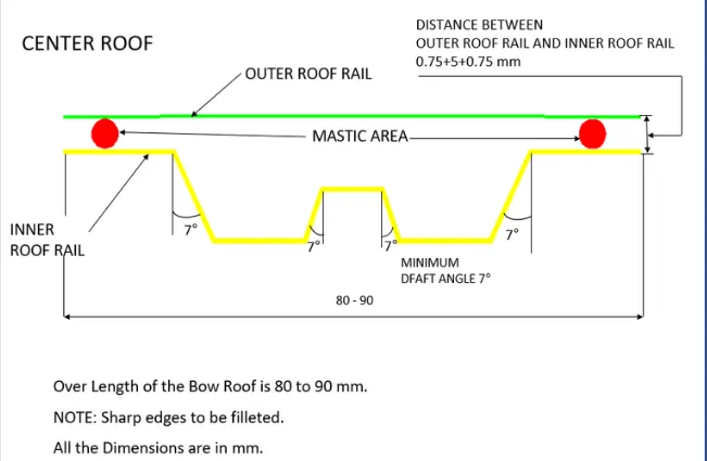
In catia the centre roof rail is modelled and is shown in the image given below.
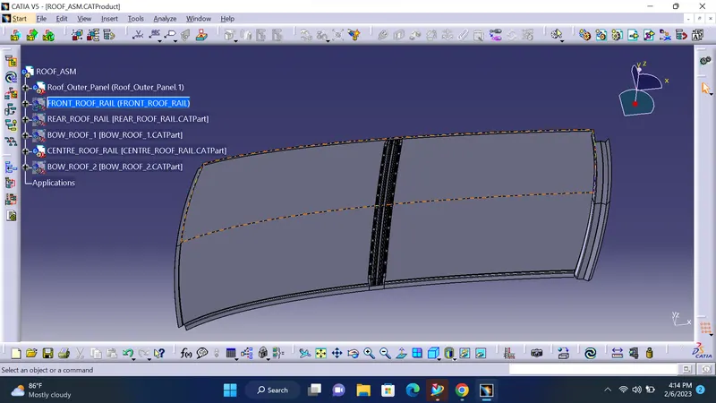
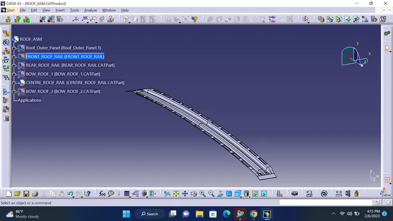
The tools used to model the Centre roof rail in Catia re.
- Paralle curve
- Copy-Paste as reference with link.
- offset surface
- Sweep-reference surface and draw direction.
- Split
- Trim
- Join
- Edge fillet
- Multi section surface
- Blend surface
- Symmetry
- Thicken etc.
In Nx cad the Centre roof rail is modelled and is shown in the image below.
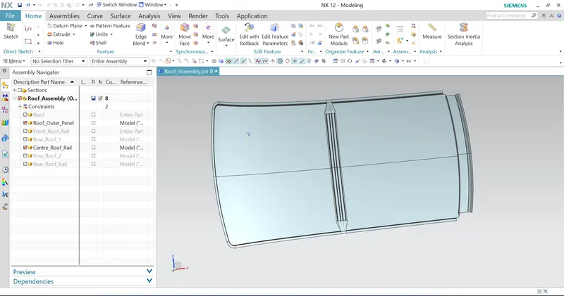
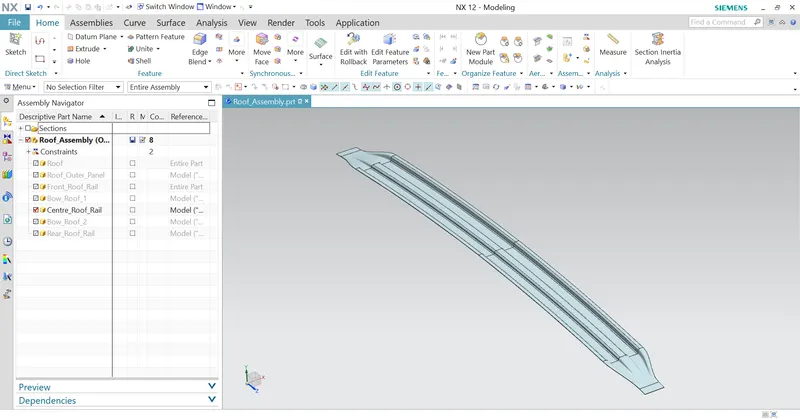
The tools used in NX cad are as follows.
- Wave Geometry Linker
- Untrim
- Bridge curve
- Extract Geometry
- Trim sheet
- Law extension
- Through curve mesh
- Offset curve in surface
- Bridge curve.
- Sew
- Edge fillet
- Thicken
- Swept surface etc.
Bow Roof 1
The Bow roof is additional support members that are attached it to roof outer panel. This will give more strength to the roof. The bow roof it's also having a master section based on which we have to model it. The master section of the bow roof is given in the image below.
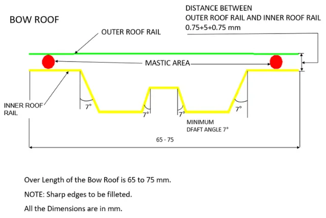
Here we can see that the master section for the bow roof it's exactly similar to the center roof rail but has a lesser width compared to the central roof rail. The bow roof is attached do the ditch area of the roof outer panel using spot welding and mastics are provided between the bow roof and roof outer panel to give more strength and reduce the NVH levels.
The bow roof is modelled in Catia and is shown below.
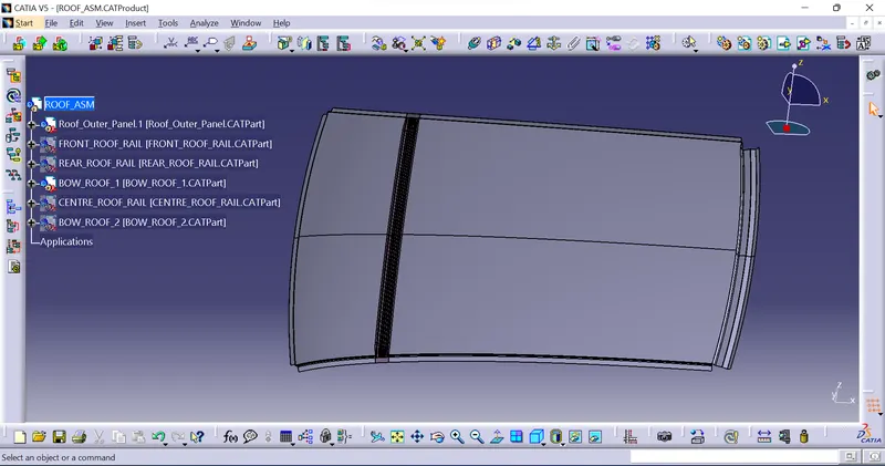
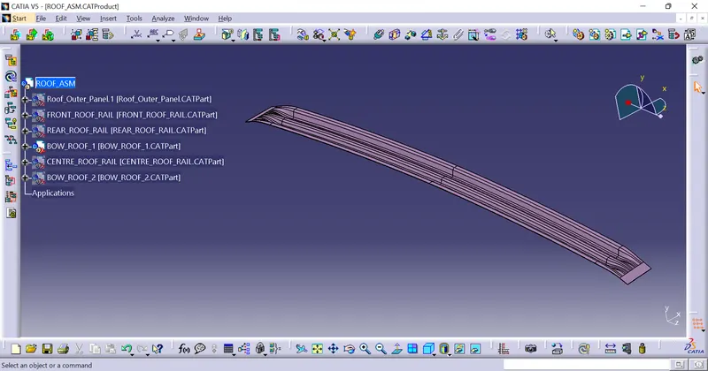
The tools used to model bow roof in Catia re as follows.
- Paralle curve
- Copy-Paste as reference with link.
- offset surface
- Sweep-reference surface and draw direction.
- Split
- Trim
- Join
- Edge fillet
- Multi section surface
- Blend surface
- Symmetry
- Thicken etc.
In Nx cad the Bow roof is modelled and the image is shown below.
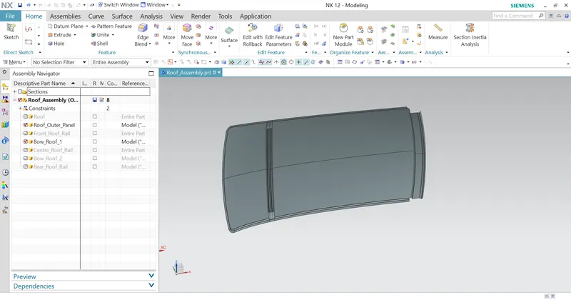
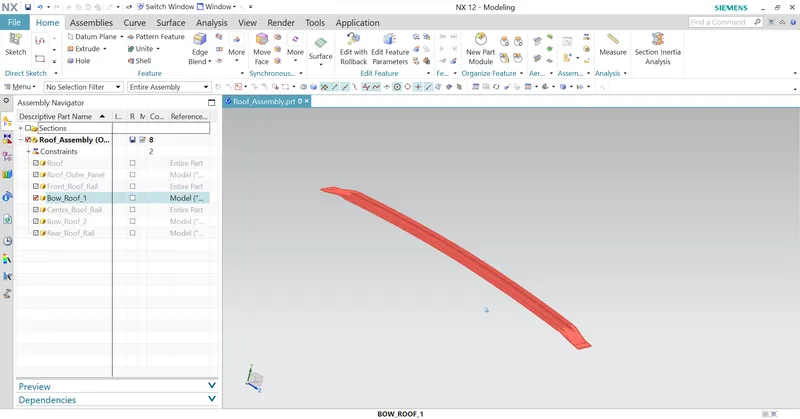
The tools used to model the bow roof NX cad are as follows.
- Wave Geometry Linker
- Untrim
- Bridge curve
- Extract Geometry
- Trim sheet
- Law extension
- Through curve mesh
- Offset curve in surface
- Bridge curve.
- Sew
- Edge fillet
- Thicken
- Swept surface etc.
Bow roof 1 and 2 are exactly identical and follows the same steps in modelling as per the master section.
After modelling each part everything is assembled.
Assembly
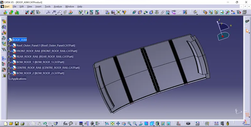
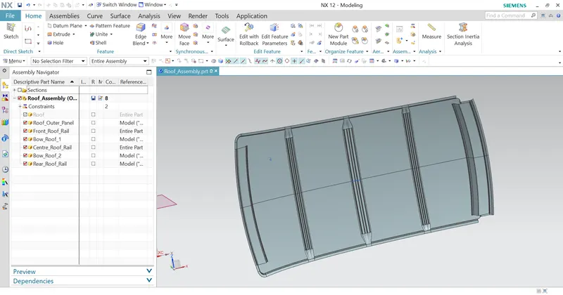
The approach followed for assembly is top down approach,so after modeling all the parts will be in its correct position withoout giving any constraints.
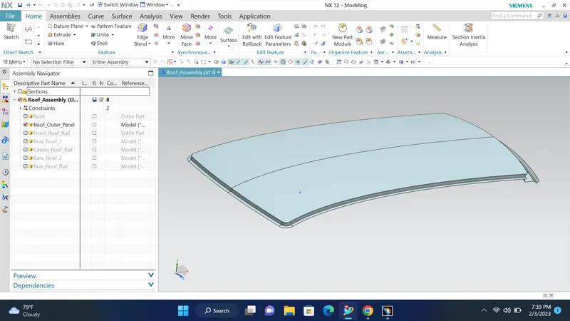
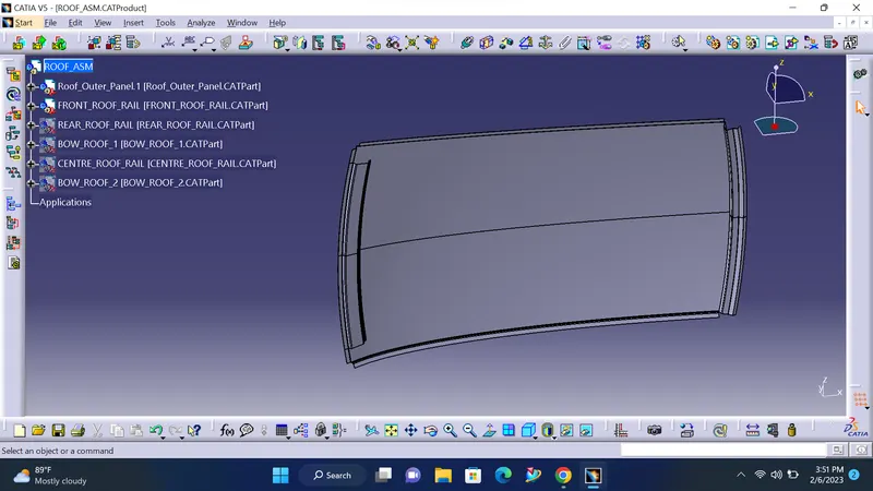
In Catia the assembly is as shown below.
In NX cad the assmbly is done and is shown below.
After creating the assembly we have to do some primary checkups on the roof assembly to validate the design.The two parameters that we are going to check are the Heat distortion criteria and snow loading criteria.
Heat distortion Criteria
This test is done to check weather the roof designed is able to withstand high temperatures.It is done by validating it with an equation as shown below.

In this equation the different terms are as follows.
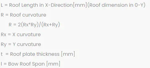
The judgement condition is as follows.
The design is ok if W<2.7
Inorder to find the radius of curvature at different sections we have to draw a sketch as shown below and find the different values as mentioned in the equation.
We have to create a new sketch in a plane parallel to the roof and then project the points onto the roof to extract the curvature information.
First draw a line through the centre,Then offset the line for a distance of 300 mm in the downward direction.
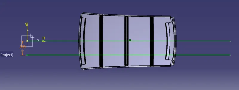
Then Offset the new line to a distance 100 mm upward and downward as shown below.
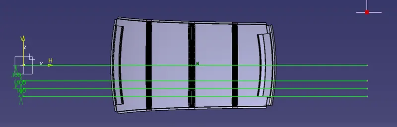
Now we need to find the centre point of the front roof rail and the bow roof 1 for the first section and then find the centre point between the centre points of the bow roof 1 and front roof rail is to be found out.So we have to extract all the end lines of the panels into the sketch as shown below.
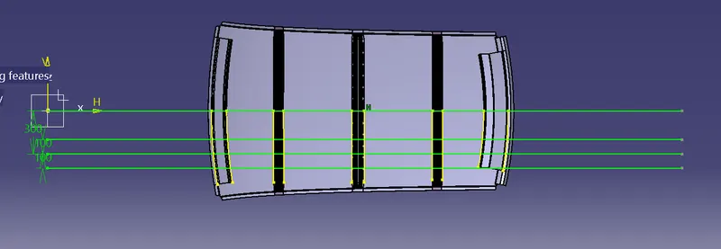
All the centre points are found out and drawn vertical lines at sections as shown below.
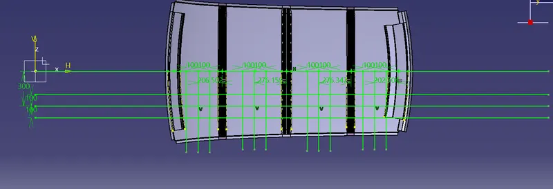
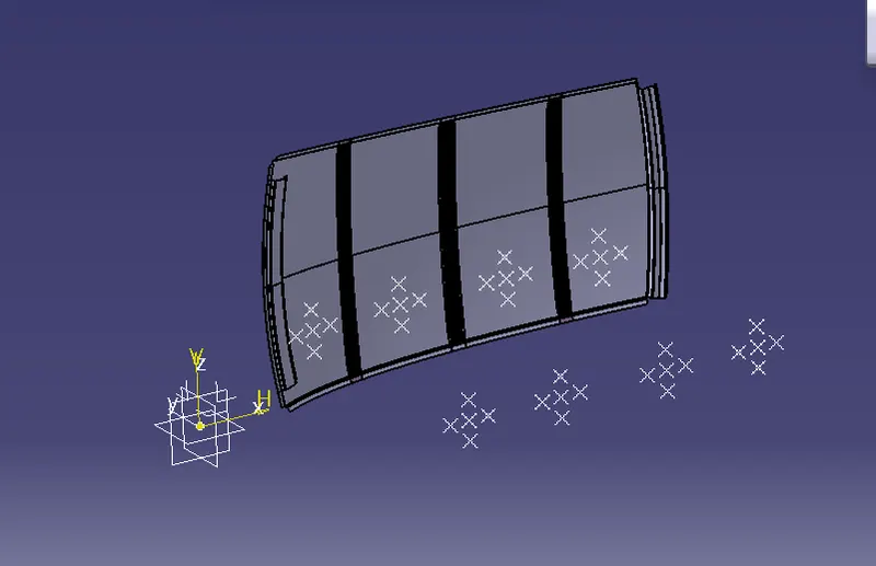
Create multiple points as shown below.
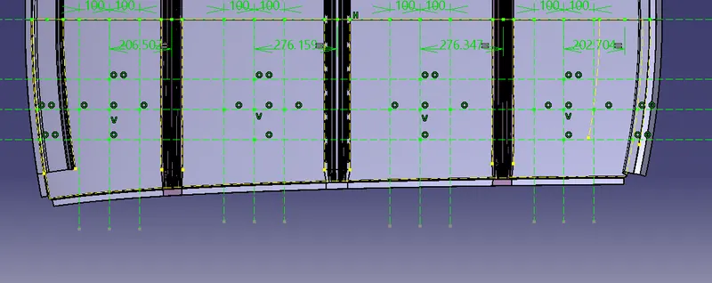
Now project the points as shown below.
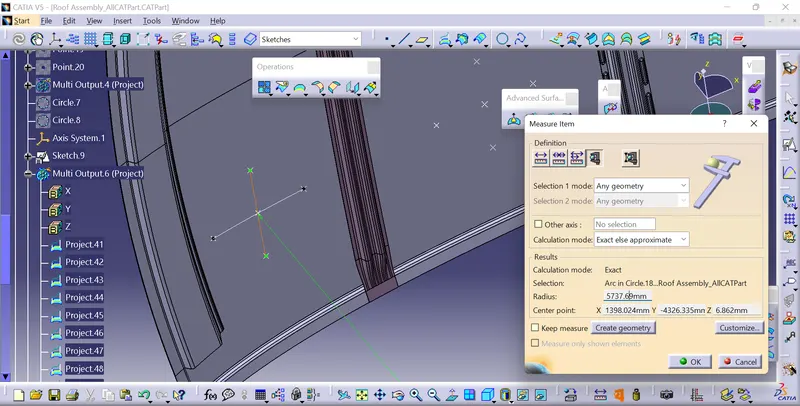
Now draw arcs with the projected curves and we can find the radius of curvature as shown below.The radius shown is the Rx for the first section.
The Heat distortion condition is calculated for all the sections and calculated using excel sheet as shown below.
Catia

NX

In our case all the conditions are satisfied.
Snow-Load Criteria
The snow load criteria is done to chect weather the roof can withstand the snowload in winter countries.

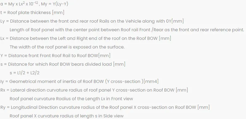
The judgement criteria is when Qr>/=3.1
In our case the snow load criteria is also found out using the Excel sheet as shown below.
The snow load criteria is found out in both softwares and is shown below.
In Catia

In NX the criteria is

In our case the snow load criterias are satisfied for all the sections in both softwares.
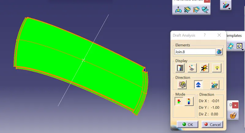
Now we have to do thw draft analysis for the different components
Roof outer panel
Front Roof Rail
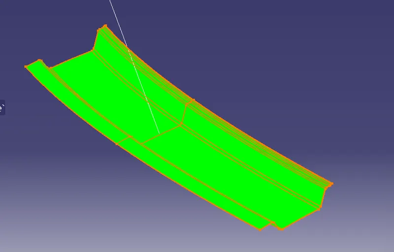
Bow roof 1
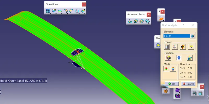
Centre Roof Rail.
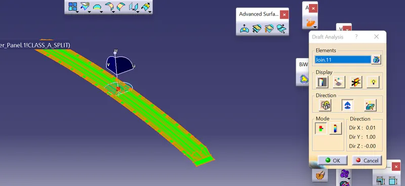
Bow roof 2
In a similar way we have to find the draft analysis in NX cad also.
Conclusion
Roof Assembly is modelled in Catia and NX cad with all its components such as Roof outer panel, Front roof rail, Rear roof rail, Centre roof rail, Bow roof 1 and Bow roof 2.All these are modelled according to the master section given.Later the roof is validated for Heat distortion and Snow loading conditions and found that our roof design and placement of the rails are according to the criteria.Files are attached along with the challenge.