Roof Design
ROOF DESIGN:
AIM:
To design the roof assembly by developing the essential flange for outer roof and create a reinforcement. Provide appropriate dimensions and check for Draft analysis. Do a curvature study on the roof and perform calculations to determine the position of the Bow-roofs.
OBJECTIVES:
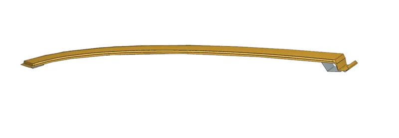
Given input of roof outer from styling team to create a flange for outer roof panel and create a reinforcement of Bow roof 1,reinforcement of center roof rail,Bow roof rail2, front roof rail and rear roof rail.
And analysis the heat distorting criteria and snow load to determine the Bow roof position.
Also clear the draft angle analysis.
INTRODUCTION:
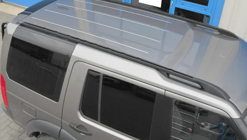
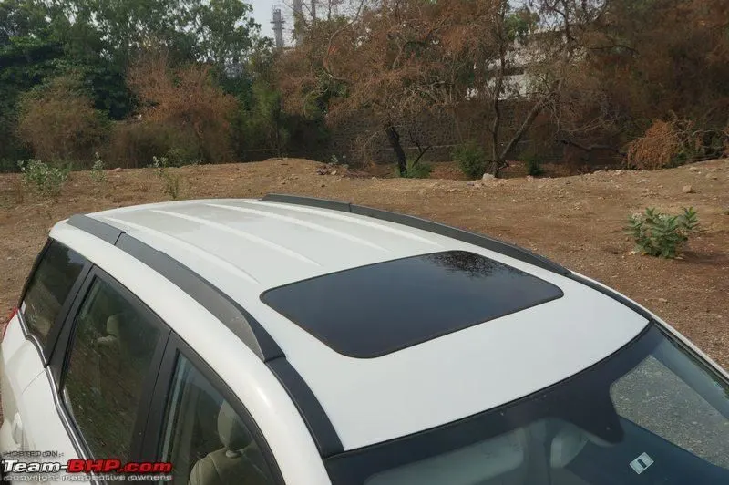
An automobile roof or car top is the portion of an automobile that sits above the passenger compartment, protecting the vehicle occupants from sun, wind, rain, and other external elements. Because the earliest automobiles were designed in an era of horse-drawn carriages, early automobile roofs used similar materials and designs.
PURPOSE OF REINFORCEMENT:
If the roof of car is flat it wil not weak roof then it will not carries the load and it will easily the break the roof. To improve that reinforcement are placed to the roof.
TYPES OF REINFORCEMENT OF ROOF:
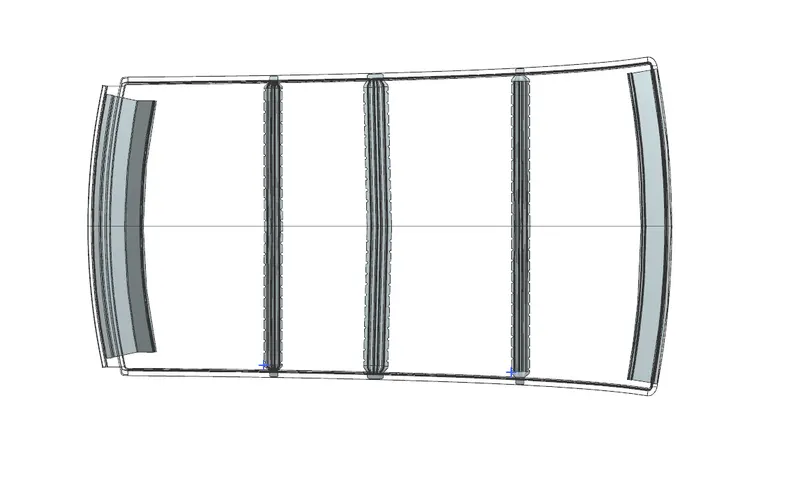
Roof consists of 5 reinforcement
- Front roof rail
- Rear roof rail
- Bow roof rail 1
- Bow roof rail 2
- center roof rail
FRONT ROOF RAIL:
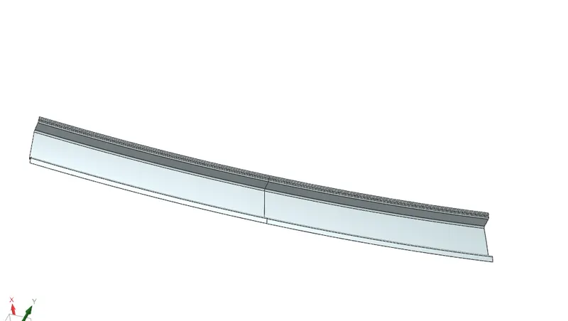
The front roof rail is located on the front of the roof where the wind shield joins with the roof. The visibility criteria and the head room clearance of the passenger are taken into consideration for the bottom flange. One end of the rail is joined using spot welding while the other end is joined with the roof using mastic sealants for increased strength.
REAR ROOF RAIL:
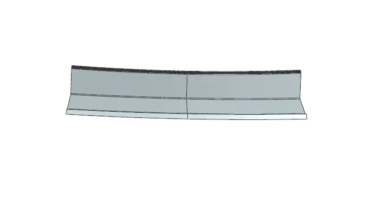
This roof rail joins with the back door and the roof. Inputs from the backdoor are taken into consideration for designing this roof rail.
BOW ROOF RAIL:
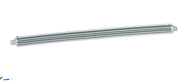
Bow roof is an additional siffening member for the roof to increase the strength and so that it can satisfy the norms. Both the ends are joined together using mastic sealants to increase strenght and also since this would not affect the styling of the roof.
CENTER ROOF RAIL:
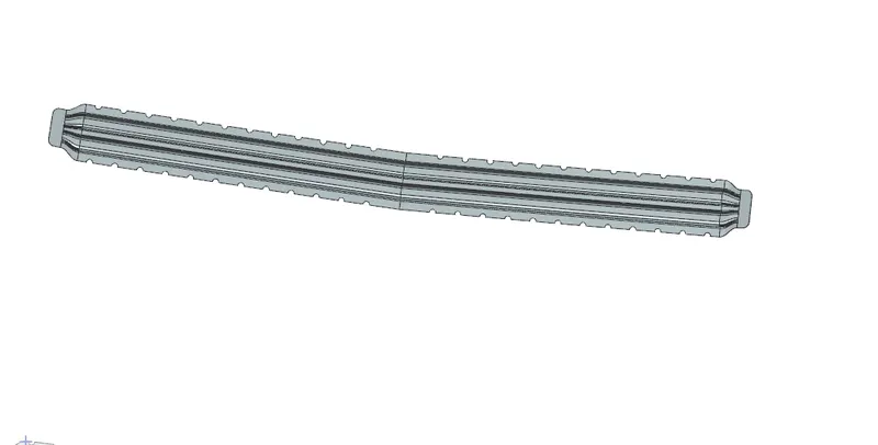
Centre Roof rail or the reinforcement centre is located at the centre of the roof . The cross section of this is more since it needs to provide more strength to the roof. Here both are ends are joined together using mastic sealants.
TESTING OF ROOF:
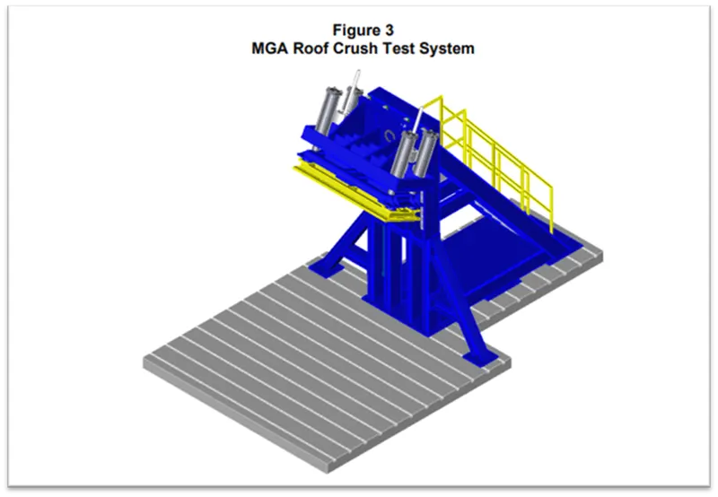
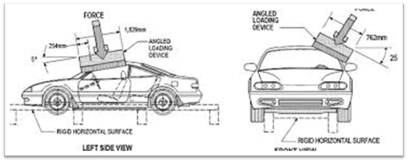
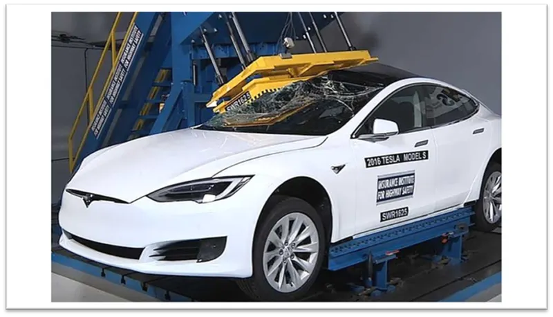
Roof strength evaluations are conducted on a quasi-static test system manufactured by MGA Research Corporation.The system consists of an upright assembly and an attached loading head that can be fixed at varying heights from the ground as well as at pitch angles ranging from −5 to +5 degrees to accommodate testing on the driver or passenger side.The roll angle is permanently fixed at 25 degrees. Four hydraulic actuators control the movement of the platen along two linear guides. The entire system is mounted on a T-slot bed plate anchored to the floor of the test facility.Two HR A-36 — W10x88 I-beams are mounted on the bed plate perpendicular to the longitudinal axis of the platen. The vehicle, with attached rocker panel support system, is placed on these beams. The vehicle is adjusted so that:
- The longitudinal centerline of platen is within 10 mm of the initial roof contact point.
- The yaw angle of the vehicle relative to the longitudinal axis of the platen is 0 ± 0.5 degrees.
- The midpoint of the platen’s forward edge is 254 ± 10 mm forward of the most forward point of the roof (including windshield trim if it overlaps the roof) lying on the vehicle’s longitudinal centerline.
- The pitch angle of the vehicle matches the on-road angle, while also accounting for any difference between the platen’s pitch angle and the nominal −5 degrees. The maximum combined difference of the vehicle and platen pitch angles from their targets is ± 0.5 degrees. (For example, if the onroad vehicle pitch angle is −0.2 degrees and the platen pitch angle is −5.2 degrees, the target sill angle for the test is −0.4 ± 0.5 degrees.) If necessary to achieve this angle, shims are inserted between the rocker panel supports and the W10x88 I-beams attached to the bed plate.
- Once the vehicle is positioned correctly, the rocker panel supports are clamped to the two perpendicular I beams, and the beams are marked to allow confirmation that the vehicle position is maintained during the test.
- For body-on-frame vehicles, the frame is supported to prevent the weight of the chassis from stressing the body at the body mounts. The roof is crushed to a minimum displacement of 127 mm at a nominal rate of 5 mm/second.
- Some tests are conducted to a greater displacement to collect additional strength data for research purposes. Force data are recorded from five load cells (Interface Inc., model 1220) attached to the loading platen.
DESIGN CONSIDERATION:
- Visibility criteria
- Head clearance
- Curvature study
- Heat distortion and snow load criteria
- Draft analysis.
HEAT DISTORTION:
The heat distortion study the plays an important role in Sheetmetal application. Heat distortion is temperature limit above which material cannot be used for structural application. This study is useful to fin the where the material starts to soften when exposed to a fixed load at elevated temperature. In order to avoid the bending, damage to the roof based on the heat distortion temperature. This study will provide the which position of the bow roof give enough strengthen to roof.
Bow Roof Prediction Formula:
HEAT DISTORTION CRITERIA:
W = [1.73 x 10^(-3) x L] + [1.85 x 10^(-8) x (R^2)/2] + [1.10 x 10^(-3) x I]-2.68
Judgement Condition: OK<2.7>3.1
Where,
L= Roof Length in X- direction [mm](Roof Dimension in 0-Y)
R = Roof curvature
R = 2(RX*RY)/(RX+RY)
RX = X Curvature
RY = Y Curvature
t = Roof plate thickness [mm]
I = Bow roof span [mm]
Thickness for the Roof(t):
Roof Outer Panel, t= 0.75mm
Front Roof Rail, t = 0.75mm
Rear Roof Rail, t = 0.75mm
Bow Roof Rail Front, t = 0.75mm
Bow Roof Rail Rear, t = 0.75mm
Reinforcement roof rail, t = 0.75mm
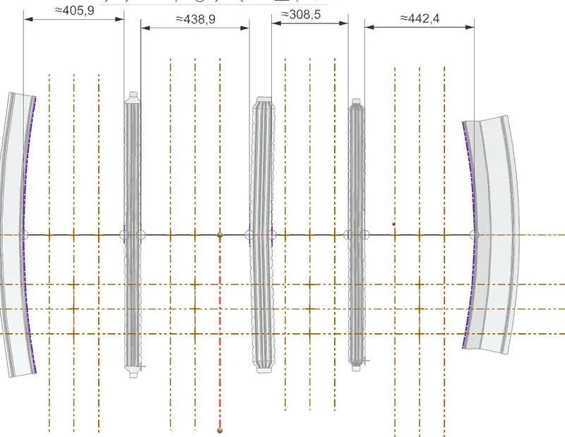
POSITION RX RY L l W RESULT
FRONT ROOF RAIL TO 1ST BOW ROOF 2639.19 5736.83 2027.7 405.9 1.35 OK
1ST BOW ROOF TO CENTER ROOF 6329.76 4918.77 2027.7 438.9 1.49 OK
CENTER ROOF TO 2ND BOW ROOF 10816.41 4020.15 2027.7 308.5 1.347 OK
2ND BOW ROOF TO REAR ROOF RAIL 15854.92 3339.41 2027.7 442.4 1.499 OK
SNOW LOAD CRITERIA:
Snow load criteria study is used to check the durability of the roof to withstand the snow fall on the roof and reflex it is original shape without any permanent deformation after load being removed.
SNOW LOAD CRITERIA:
Qr = [IY x t2] / [α x s x [(RX + RY)/2]2 x 10-8]
Where,
α = My x LX2 x10-12, My = Y(Ly–Y)
Judgement condition = Qr > 3.1
250 < s < 380
t = Roof plate thickness[mm]
LY = Distance between the front and rear roof rails on the vehicle along with 0Y[MM],
Length of roof panel with the center point between roof rails front/ rear as the front and rear reference point.
LX= Distance between the left and right end of the roof on the roof bow[mm],
With of the roof panel exposed on the surface.
Y = Distance between Front roof rails to roof bow [mm],
s = Distance for which roof bow bears divided load [mm],
s = L1/2 + L2/2
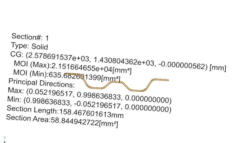
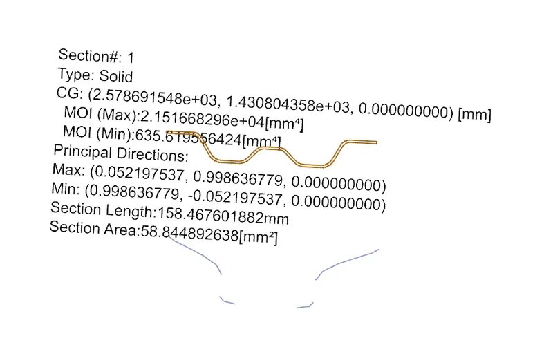
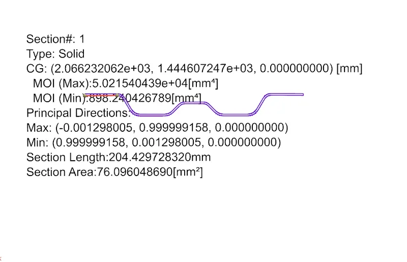
Iy = Geometrical moment of inertia of roof bow (Y cross – section) [mm4],
RX = Lateral direction curvature radius of roof panel Y cross section on roof bow [mm4],
Roof panel curvature radius of the length LX in front view.
RY = Longitudinal direction curvature radius of the roof panel X cross section on roof bow[mm4],
Roof panel X curvature radius of length s in side view.
RX & RY (X & Y Curvature):
At 0-Y axis on perpendicular plane to roof. Draw 100mm lines offset to either side of the of 0Y axis line. Now center lines are drawn between each adjacent roof rail respective. Intersection points are marked on the sketch. Make all the geometry in construction lines except points.
Project the intersection points in the sketch are projected to roof surface.
Join the project points using arc curve and measure the radius value using minimum radius comment.
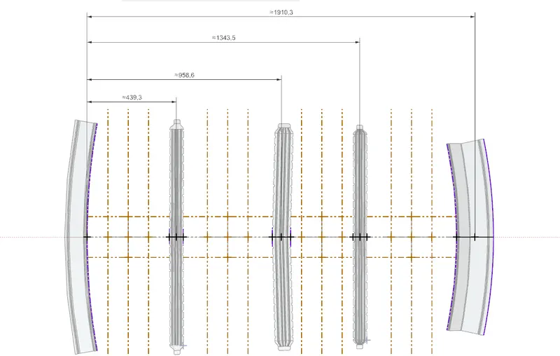
POSITION RX RY S LX LY Y α QR RESULT
FRONT ROOF TO 1ST BOW ROOF 4503.55 2637.76 422.9 1033.7 2027.7 439.3 0.89 7.4 OK
1ST BOW ROOF TO CENTER ROOF 3775.2 6328.86 374.2 1082.1 2027.7 959.6 1.20 4.4 OK
CENTER ROOF TO 2ND BOW ROOF 4254.27 10815.93 375.45 1056.5 2027.7 1343.5 0.25 6.7 OK
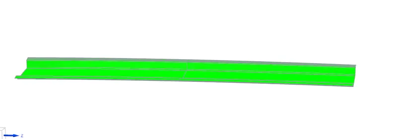
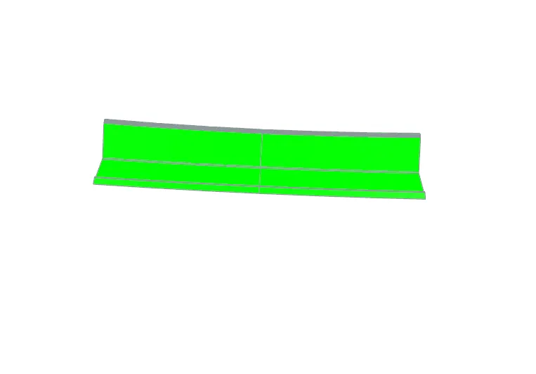
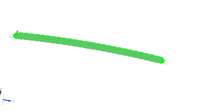
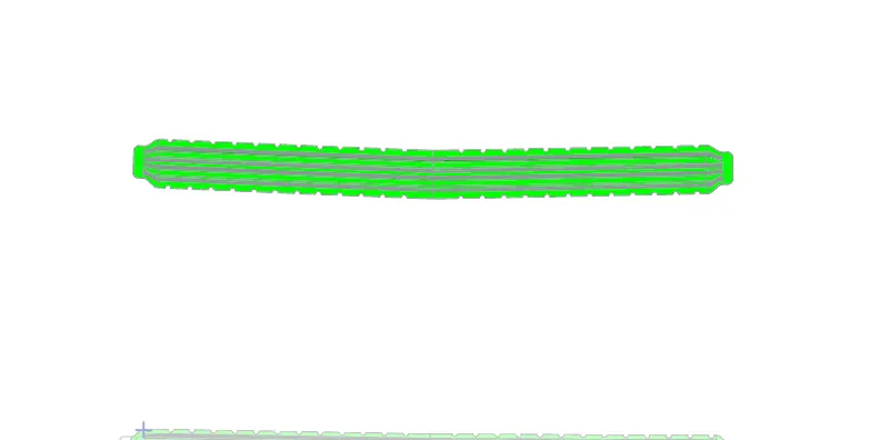
DRAFT ANALYSIS:
MOMENT OF INERTIA:
FINAL MODEL:
CONCLUSION:
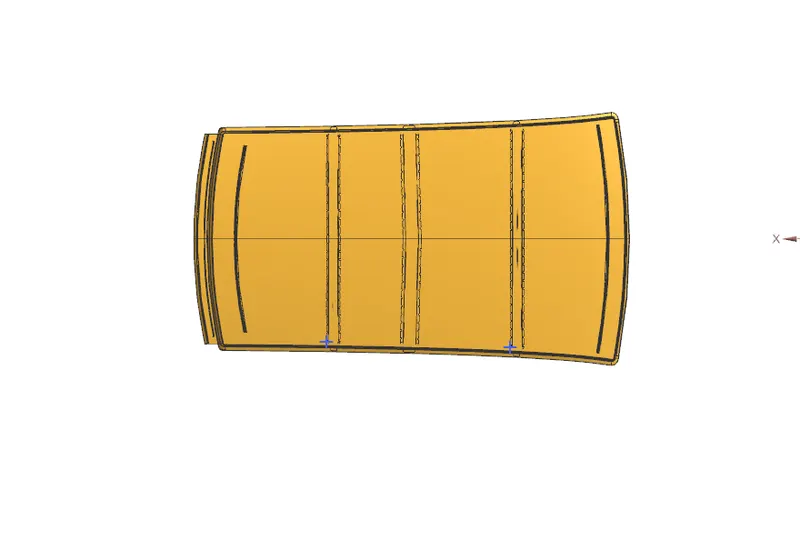
Design the roof assemble with development of flange at the given master section with design consideration and At the study of curvature of position of bow roof is cleared in the heat distortion and snow load criteria.