Roof Design
Roof challenge
AIM:
Design of the front roof rail, rear roof rail, and bow roof for the roof of the vehicles with the help of the given skin data of the roof according to snow load condition and hear distortion criteria.
INTRODUCTION:
An automobile roof or car top is the portion of an automobile that sits above the passenger compartment, protecting the vehicle occupants from sun, wind, rain, and other external elements. Because the earliest automobiles were designed in an era of house-drawn carriages, early automobile roofs used similar materials and designs.
The roof is a styling surface part that is fixed with the BIW body through the rails and panels inside the upper roof to provide it strength and stiffness.
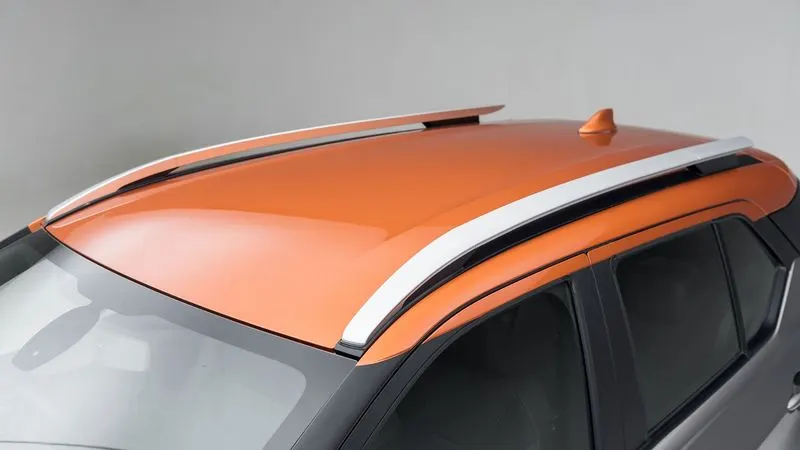
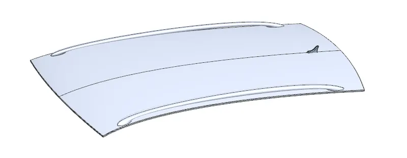
The rails and reinforcement are joined to the ditch area with a spot weld where it’s not the styling part.
The required tool opening angle is a minimum of 3 Degrees.
Factors that are considered before creating the Roof
- Headroom Clearance
- Visibility Criteria
- Back door Assembly
- Windshield Assembly
Common Roof Part
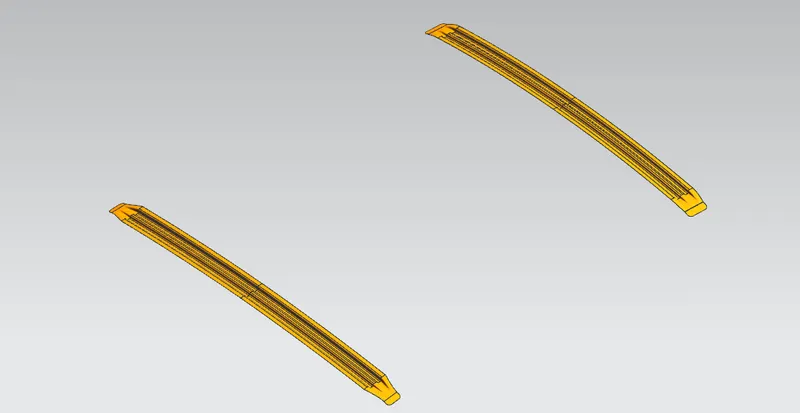
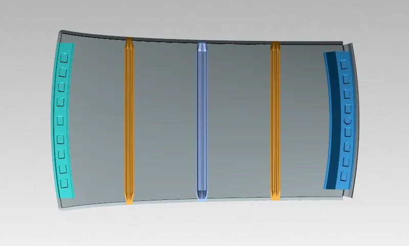
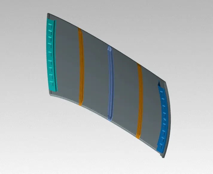
- Front roof rail reinforcement (FR)
- Bow roof rail reinforcement 1 (BR1)
- Center roof rail reinforcement primary (CR)
- Center roof rail reinforcement secondary
- Bow roof rail reinforcement 2 (BR2)
- Rear roof rail reinforcement (RR)
The quantity of Bow depends on the length of the roof and analysis when the roof length is more then the Bow quantity is increased.
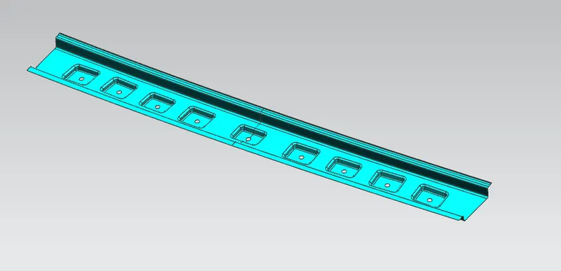
Front roof rail reinforcement (FR)
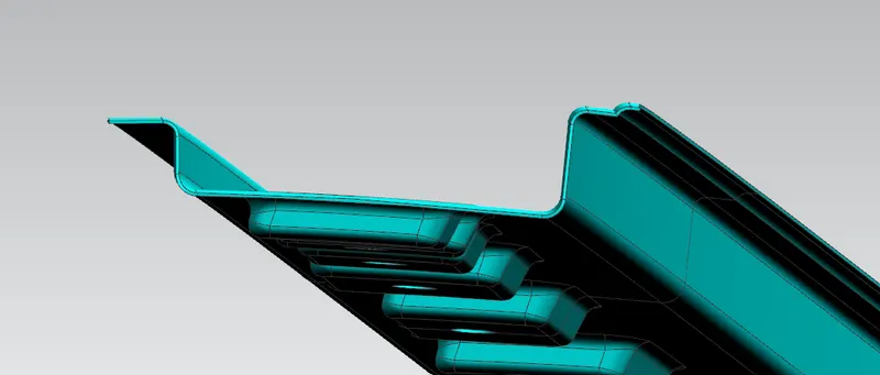
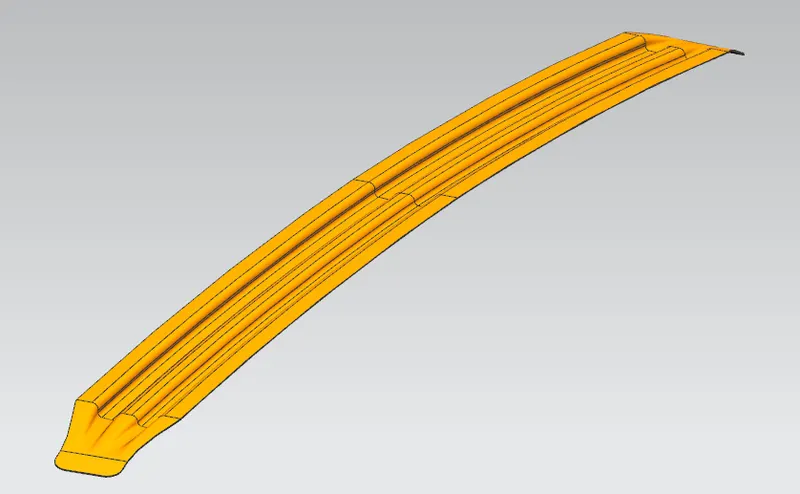
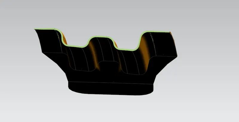
The Front Roof rail was designed based on the master section given.
It is the support that joins the windshield glass, the body side outer, and the inner panels. It is usually made from body side outer scrap and therefore the thickness of the rail is 1.25 mm. A draft angle of 3-5 degrees is provided for deep drawing operation. The visibility criteria and the headroom clearance of the passenger are taken as design considerations.
2. Bow roof rail 1 and 2 reinforcement-
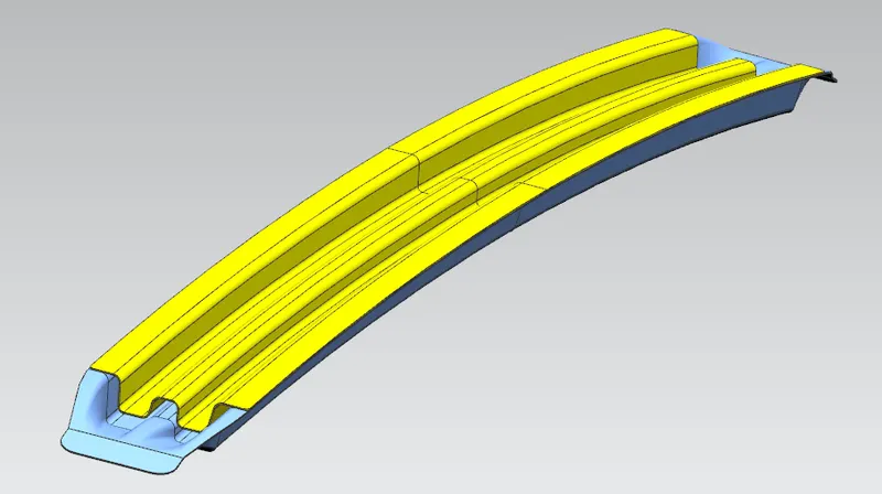
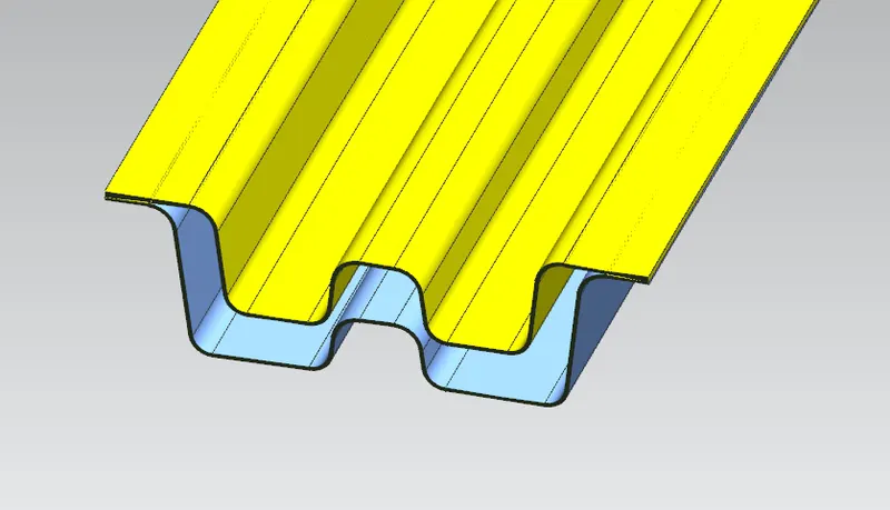
BOW 1 & 2 is an additional roof member used in the roof assembly to increase the strength of the roof. It is joined directly to the roof with the mastic sealant. Creating the Bow 1 then min. draft angle is 7 deg. required.
These are the intermediate structural components of the roof that are added in order to provide support along with the three primary roof rails (FR, CR, RR). The number of bow roof rails may vary depending on the class of the vehicle. Some vehicles may not have a bow roof at all. It all depends on the design intent.
3. Center roof rail reinforcement (CR)-
The Center roof rail helps in providing support to the flat area of the roof as it is more susceptible to failure under the action of load. Generally, the center roof rail is placed at the center of the roof which is connected to the B-pillar support structure. The Center roof rail helps in adding strength to the roof during the roll-over test. Creating the center roof rail then min. draft angle is 7 deg. required.
In the Center roof rail, used reinforcement also. Reinforcement is giving more strength to the roof and center roof rail. The Center roof rail is used in the center of the roof and this area is a flat area as compared to the other area so this area required more strength and stiffness that reason used the reinforcement and center roof rail.
4. Rear roof rail reinforcement (RR)-
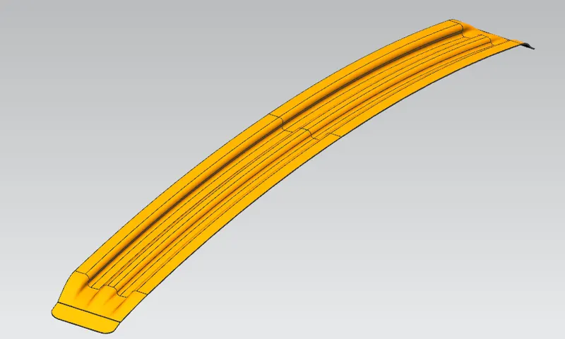
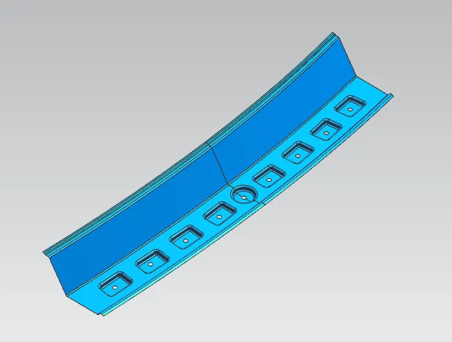
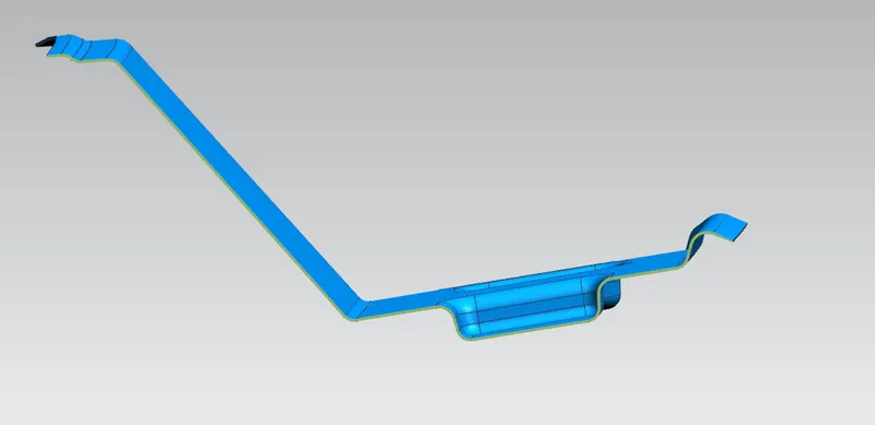
It is the support that is joined to the backdoor the bodyside outer and the inner panels. Inputs from the backdoor design are also taken to accommodate their required clearance along with headroom clearance and the rear visibility criteria while designing the rear roof rail. Spot welds are applied at the backdoor end of the rail and the other end is joined with the roof using mastic sealants.
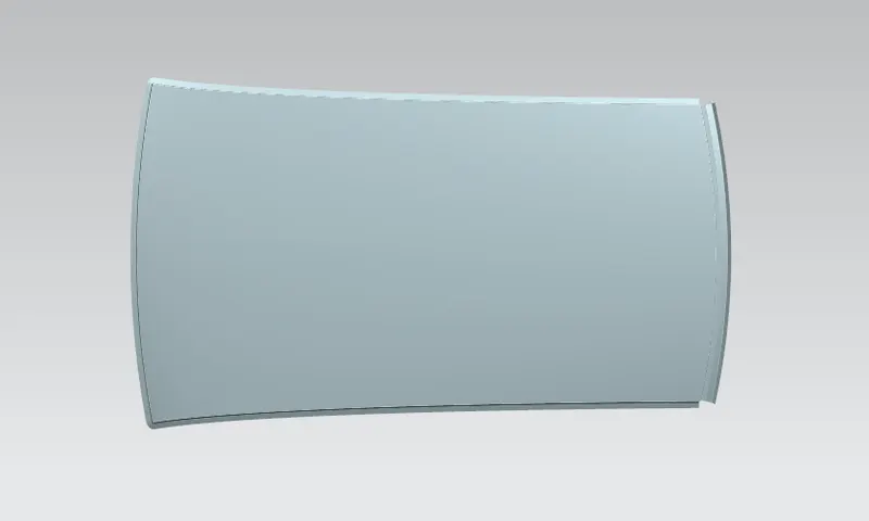
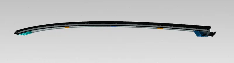
Complete roof design
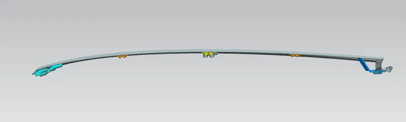
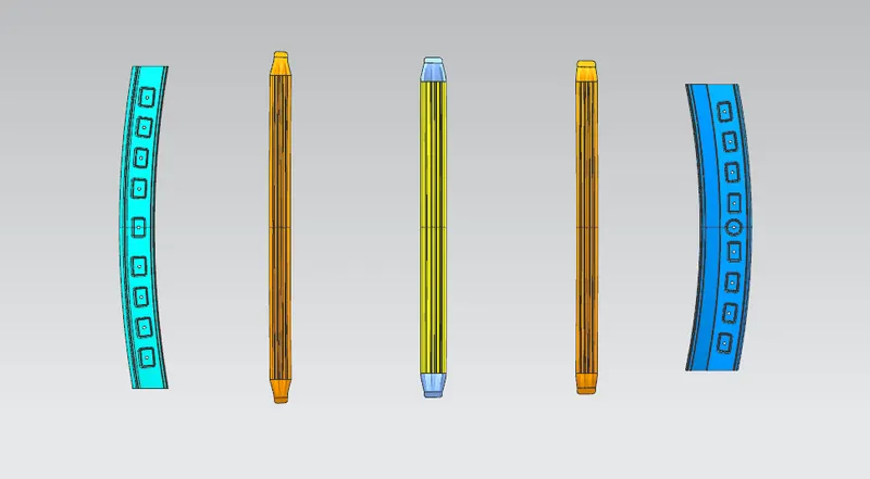
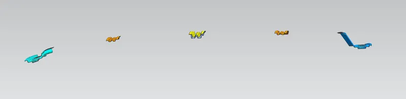
The calculation for determining the bow roof position:
Heat distortion criteria-
Heat distortion temperature is the temperature at which the metal softens and deforms under a specific load. This study is done to check the ability of the roof to withstand high temperature with respect to the positioning of the reinforcements which contribute to increased strength.
Created sketches for heat distortion calculation:
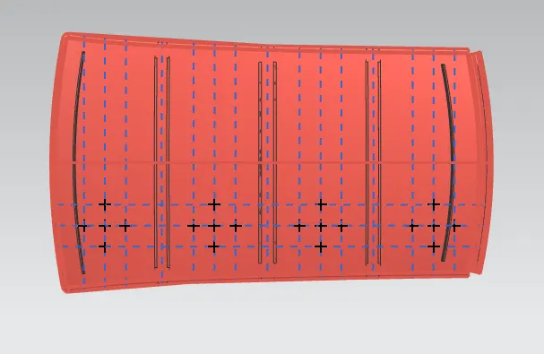
Heat distortion prediction formula
W=[1.73×10^(-3)×L]+[1.85×10^(-8)×(R^2)/t]+[1.10×10^(-3)×I]-2.68
Judgment condition- OK<2.7>3.1
Where
L=Roof length in X- Direction[mm](Roof dimension in 0-Y)
R= Roof curvature
R= 2(Rx×Ry)/(Rx+Ry)
Rx= X Curvature
Ry= Y Curvature
T= Roof plate thickness[mm]
I= Bow roof span [mm]
|
BOW |
Rx |
Ry |
R |
I |
L |
t |
W |
OK/NG |
|
FR&BR1 |
5753.19 |
2195.72 |
3178.60 |
381.56 |
2032.51 |
0.75 |
1.46 |
OK |
|
BR1&CR |
4971.27 |
6232.62 |
5531.44 |
428.45 |
2032.51 |
0.75 |
2.05 |
OK |
|
CR&BR2 |
3984.83 |
10499.42 |
5777.08 |
428.70 |
2032.51 |
0.75 |
2.12 |
OK |
|
BR2&RR |
3189.76 |
15243.62 |
5375.59 |
337.09 |
2032.51 |
0.75 |
1.97 |
OK |
From the above results, it is concluded that the desired designed roof satisfies the heat distortion criteria.
Snow load criteria-
Snow load criteria study is done to check the ability of the roof to withstand snowfall and bounce back to its original shape without any permanent deformation once the load is removed.
Created sketches for snow load criteria:
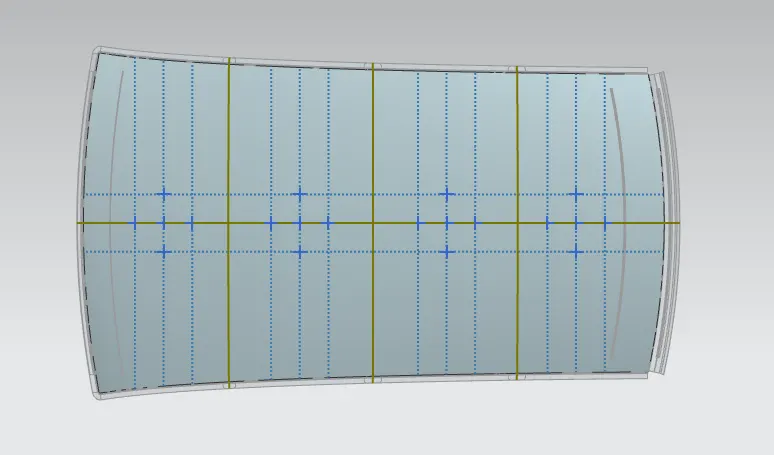
Snow load prediction formula-
Qr = [Ly×t^2]/[α×s×[(Rx+Ry)/2]^2×10^-(8)]
Where
α = My×Lx^2×10^-12
My= Y(Ly-Y)
Judgment condition =Qr≥3.1 and 250≤Qr≤380
T = Roof plate thickness
Ly = Distance between the front and rear roof rail on the vehicle along with 0-Y
Lx = Distance between the left and right end of the roof on the roof bow.
Y = Distance for which roof bow bears the divided load
S = Distance for which roof bow bears the divided load
S= L1/2+L2/2
Iy = Geometrical moment of inertia of roof bow along Y cross-section
Rx = Lateral direction curvature radius of roof panel along Y cross-section
Ry = Longitudinal direction curvature radius of the roof panel along X cross-section
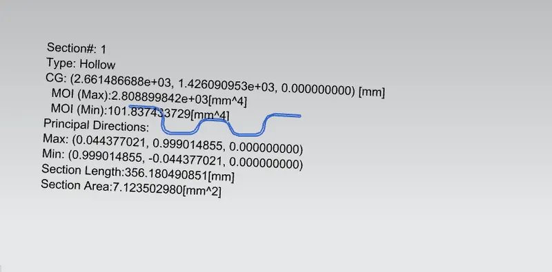
Moment of Inertia for the roof rails:-
Fig: MOI of bow roof_1
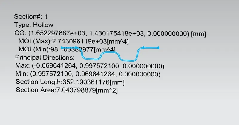
Fig: MOI of Center Reinforcement Rail
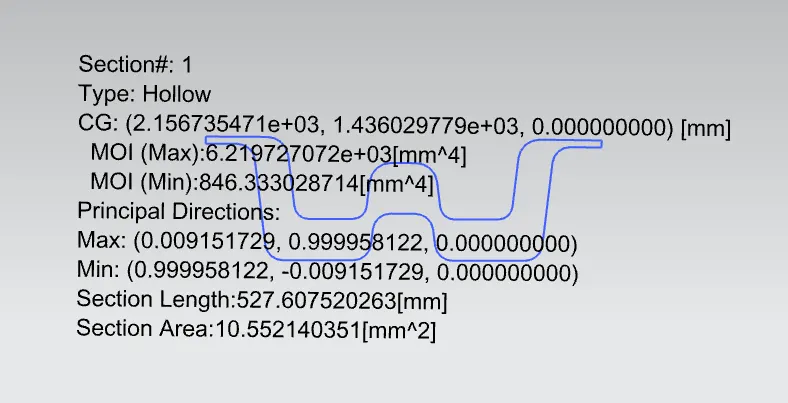
Fig: MOI of bow roof_2
CALCULATION:
|
BOW |
Lx |
Ly |
Rx |
Ry |
α |
Iy |
s |
t |
y |
Qr |
OK/NG |
|
FR-BR1 |
1140.68 |
2032.51 |
4562.67 |
2259.56 |
0.96 |
2743.09 |
492.02 |
0.75 |
478.24 |
28.07 |
OK |
|
BR1-CR |
1089.18 |
2032.51 |
3769.26 |
6097.30 |
0.91 |
6219.72 |
505.86 |
0.75 |
505.81 |
31.22 |
OK |
|
CR-BR2 |
1061.37 |
2032.51 |
4261.25 |
11066.86 |
0.87 |
2808.89 |
486.17 |
0.75 |
505.91 |
6.35 |
OK |
From the above result, it is concluded that the designed roof satisfies the snow load criteria.
Section modulus study
Section modulus is a geometrical property for a given cross-section used on the design of beams or flexural members. Other geometrical properties used in the design include an area for tension and shear, the radius of gyration for compression, the moment of inertia, and the polar moment of inertia for stiffness. Any relationship between these properties is highly dependent on the shape. There are two types of section modules.
- Elastic section modulus
- Plastic section modulus
the elastic section modulus is defined as,
S=I/Y
S= section modulus
I= moment of inertia
Y is the distance between the neutral axis to the most extreme fiber.
Front roof rail:
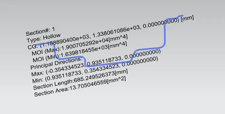
Moment of inertia(max) = 1.9007×10^4×mm^4
Moment of inertia(min) = 1.6398×10^3×mm^4
Y=123.97/2=61.98 mm
S=I/Y
S=1.6398×10^3/61.981= 26.45 mm^3
Rear Roof Rail:
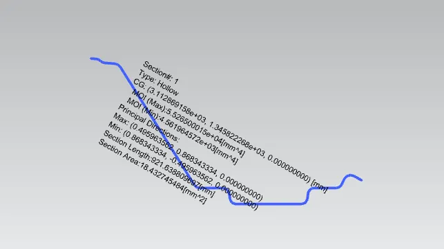
Moment of inertia(max) = 5.5265×10^4
Moment of inertia(min) = 4.5619×10^3×
Y=185.49/2=92.745 mm
S=I/Y
S=4.5619×10^3/92.745= 49.18 mm^3
similarly, we can calculate the section modulus, bow roof_1, center roof rail, bow roof_2
Conclusion
Thus the roof of the car is designed as per the given skin data and master sketch. The roof is also analyzed as per the heat distortion and snow load conditions and is found to be within limits.
THANKS