Roof Design
Roof design
Aim:
- To create an assembly by developing the essential flanges for the outer roof and creating the necessary reinforcements for the outer panel
- To provide appropriate dimensions according to the master section provided
- To verify the minimum draft angle criteria for all the parts using draft analysis
- Perform calculations to determine the position of the Bow-roofs Based on the heat distortion and snow load criteria.
Introduction:
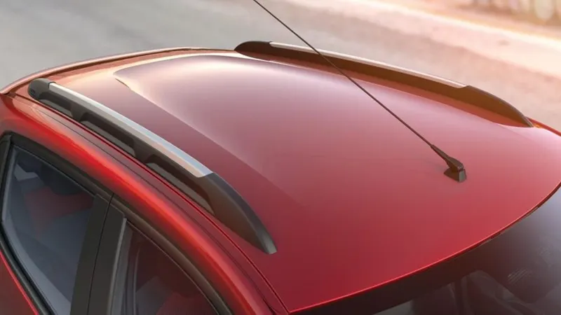
An automobile roof or car top is the portion of an automobile that sits directly above the passenger compartment, protecting the vehicle occupants from sun, wind, rain dust and all other external elements present in the environment. The roof is connected to the body sides and also the front and rear sections of the car. The roof panel is an assembly consisting of various cross members which serve the purpose of increasing the rigidity and strength of the roof and hence the car body structure. The roof also contributes to the overall aerodynamics of the car and hence is a very important factor considered while designing roof and its accessories.
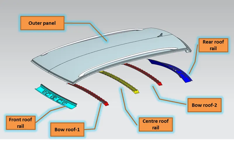
Components of hood:
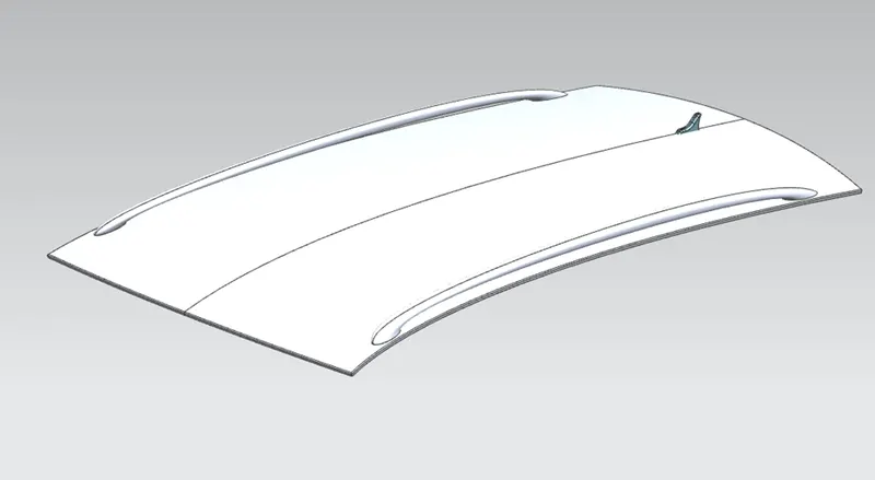
Roof outer panel
The outer panel of the roof is the styling part of the roof assembly and it is supposed to be aesthetic in looks while also not affecting the air flow over the car in a bad manner. This panel is created by the class A surface designers and is then given as an input to the engineering team which then creates the necessary reinforcements for the outer panel. The outer panel also consists of accessories such as the side roof rails, antenna and sun roof panel
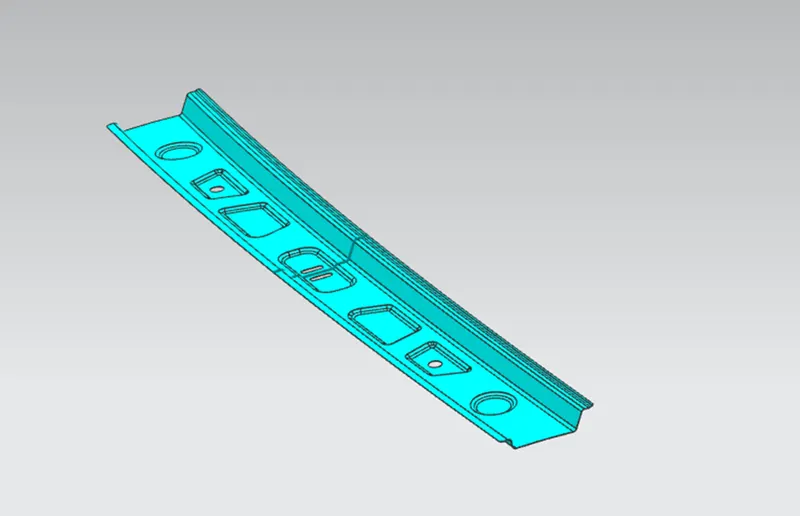
Front roof rail
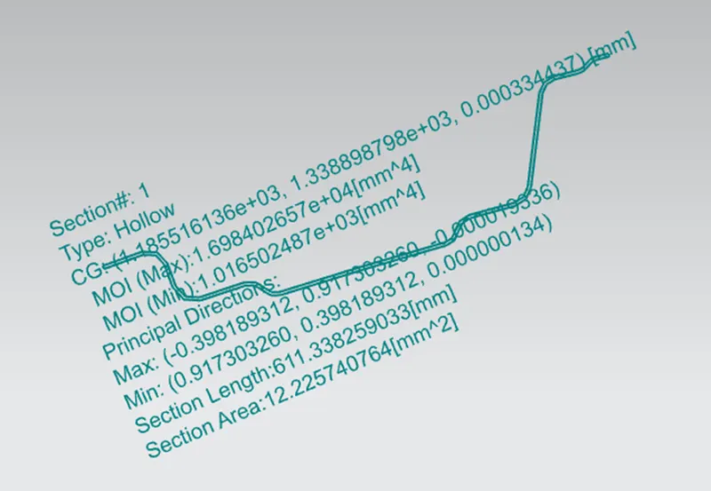
Front roof rail is a cross member located in the front portion of the roof used to provide strength to the roof panel it also acts as link between windshield glass, roof panel and headliner(interior trim)
Rear roof rail
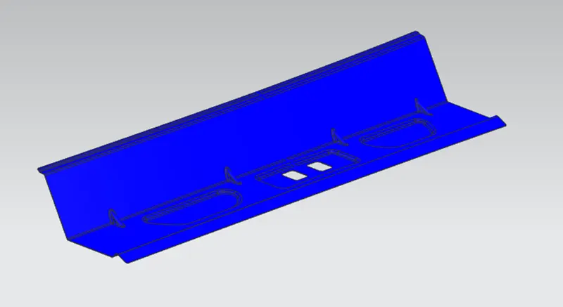
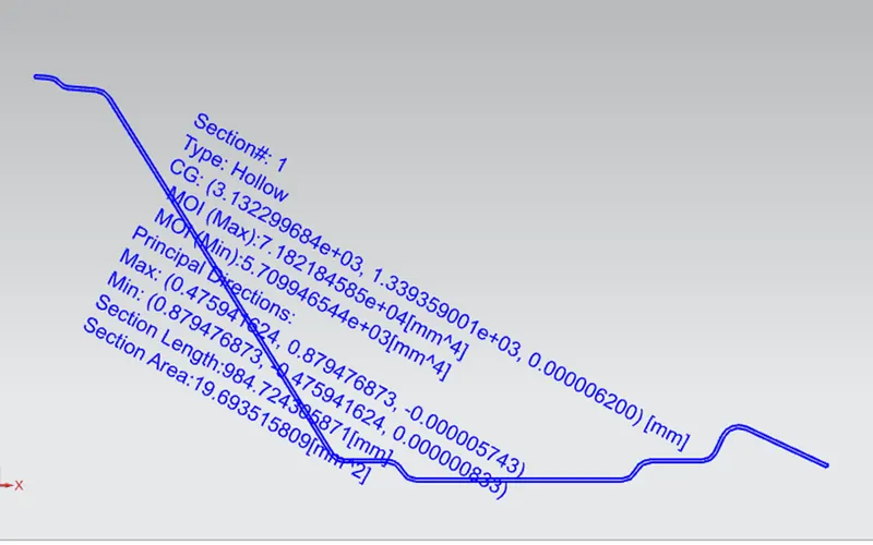
The rear roof rail is a cross member located in the rear portion of the roof. Rear roof rail also joins along with the body side and the tailgate assembly
Centre roof rail
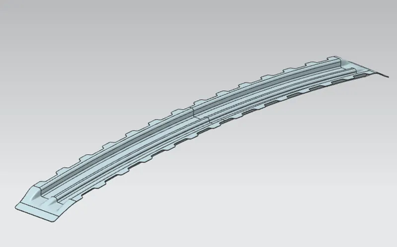
Central roof rail as the name suggest is located near the central and flat portion of the roof assembly. It is generally connected along with the B pillar support structure and its main purpose is to provide strength to the roof during the event of any accident (especially rollover).In case of cars which have a sunroof the centre roof rail comes with another reinforcement along with it to compensate for the loss of strength in the sunroof region.
Bow Roofs
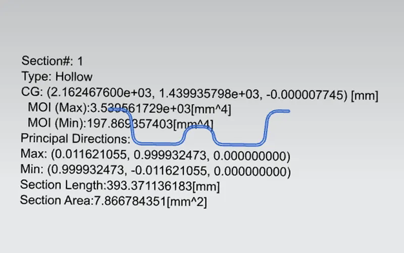
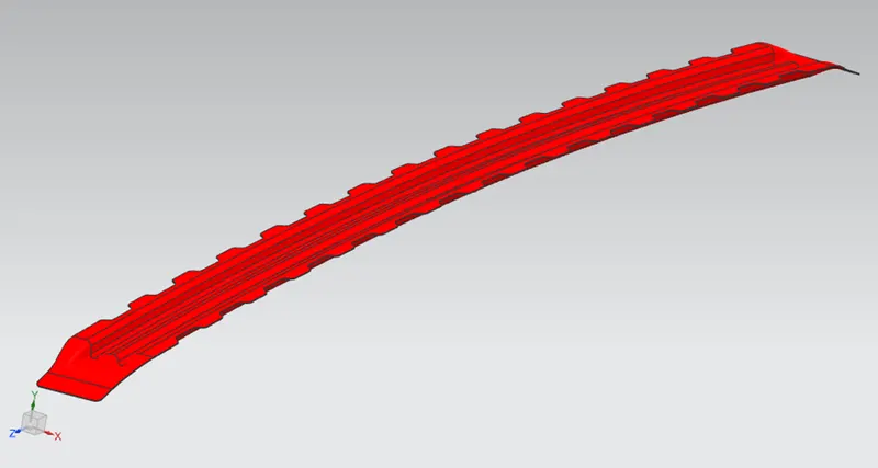
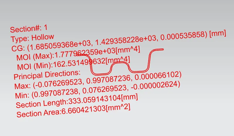
The Bow roofs are provided to improve the torsional stiffness and the overall strength of the roof. The number of bow roofs placed depends upon the overall size of the roof. It can vary anywhere between two to four in case of common commercial vehicles. In our case we have made use of two bow roofs.
Design considerations:
Master Section
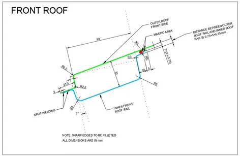
The master section provides us with the basic dimensions of the reinforcemsnts.it also provides the distance of each surface of the inner reinforcements from the outer class a surface of the roof. These dimensions must be strictly followed to ensure there is no interference between components during the final assembly process
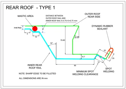
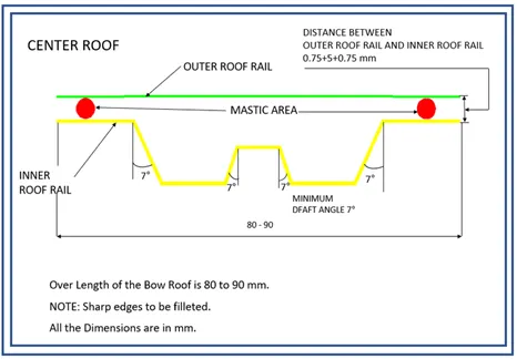
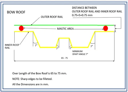
Visibility Criteria and Head room Clearance.
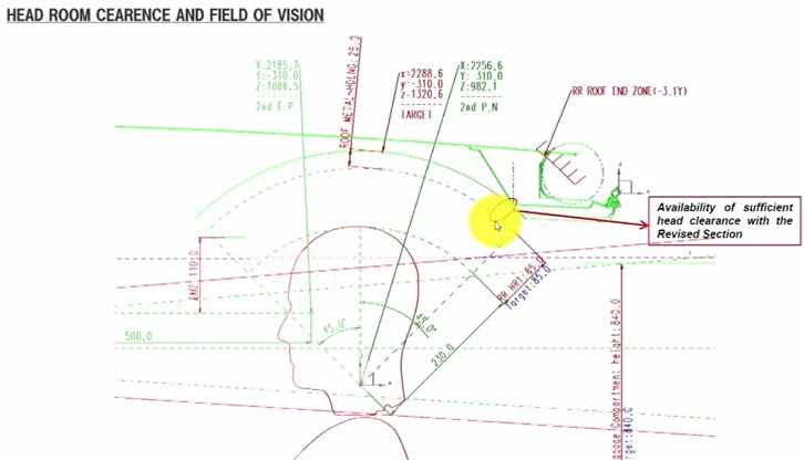
Before designing the actual reinforcements, factors such as the head room clearance in the cabin and the field of vision must be checked and it must be ensured that they fall within the standards. The master section can be used in this case to verify for the head room clearance as shown in the image below.
Curvature Study.
Heat Distortion Criteria.
Heat distortion criteria is a study done to predict the heat distortion temperature. It is the temperature at which the material starts to soften and distort when exposed to a certain fixed load at an elevated temperature. This is done to make sure that the roof reinforcements are placed properly such that any bending or damage to the roof in such conditions is avoided and the roof structure has proper strength
Bow–Roof Prediction Formula
W = [1.73 x 10^(-3) x L] + [1.85 x 10^(-8) x (R^2)/t] + [ 1.10x10^(-3) x l] - 2.68
Where,
L = Roof Length in X-Direction[mm](Roof dimension in 0-Y)
R = Roof curvature
R = 2(Rx*Ry)/(Rx+Ry)
Rx = X curvature
Ry = Y curvature
t = Roof plate thickness [mm]
l = Bow Roof Span [mm]
Judgment Condition : OK< 2.7>3.1

From the above table it can be concluded that all values of w<2.7 and also not w>3.1 which indicates that the positioning of the bow roofs has been done properly
Snow Load Criteria
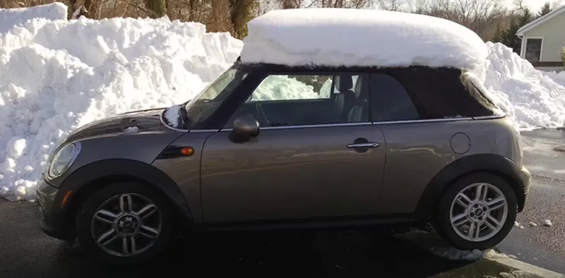
The snow load criteria involves a test which study’s the behaviour of the roof under the application of snow on it. Usually when the roof is covered with heavy snow there are chances that the structure deforms a bit and does not return to its original shape when the snow is removed. In order to analyse this condition the snow load test is performed.
Snow Load Prediction Formula
Qr = [Iy x t2] / [α x s x [(Rx + Ry)/2]2 x 10-8]
Where,
a = My x Lx2 x 10-12 , My = Y(Ly-Y)
t = Roof plate thickness [mm]
Ly = Distance between the front and rear roof Rails on the Vehicle along with 0Y[mm]
Length of Roof panel with the center point between Roof rail Front /Rear as the front and rear reference point.
Lx = Distance between the Left and Right end of the roof on the Roof BOW [mm]
The width of the roof panel is exposed on the surface.
Y = Distance front Front Roof Rail to Roof BOW[mm]
s = Distance for which Roof BOW bears divided load [mm]
s = L1/2 + L2/2
Iy = Geometrical moment of inertia of Roof BOW (Y cross-section )[mm4]
Rx = Lateral direction curvature radius of roof panel Y cross-section on Roof BOW [mm]
Roof panel curvature Radius of the Length Lx in Front view
Ry = Longitudinal Direction curvature radius of the Roof panel X cross-section on Roof BOW [mm]
Roof panel X curvature radius of length s in Side view
Judgment condition
Qr ≥ 3.1
250 ≤ s ≤ 380

From the above table it can be concluded that all values of Q>3.1 which indicates that the positioning of the bow roofs has been done properly
Safety:
Safety is one of the most important criteria while designing automobile components and roof plays a major role in the safety of the occupants especially during roll overs.A properly designed roof must be able to withstand the impact force without much deformation and hence increase the chance of survival of the occupants during a collision or a roll over.
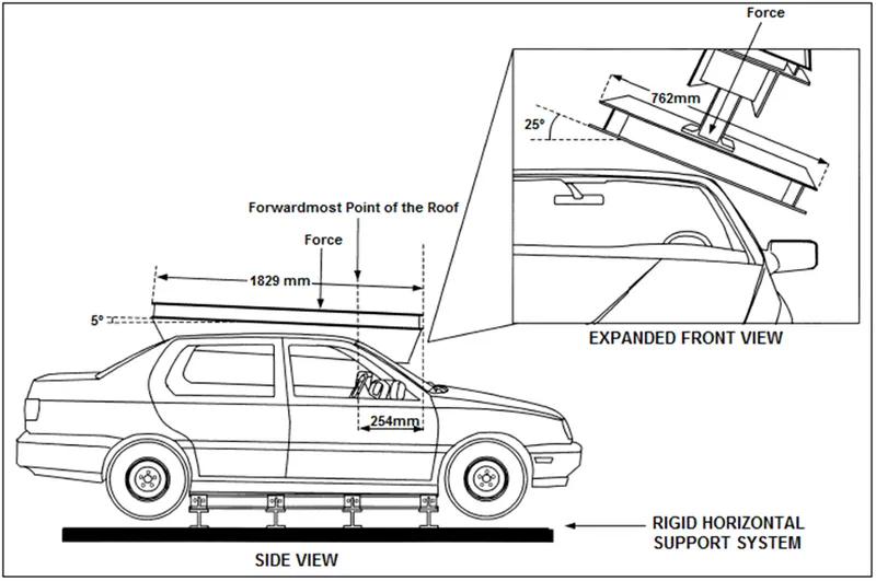
Roof crush test
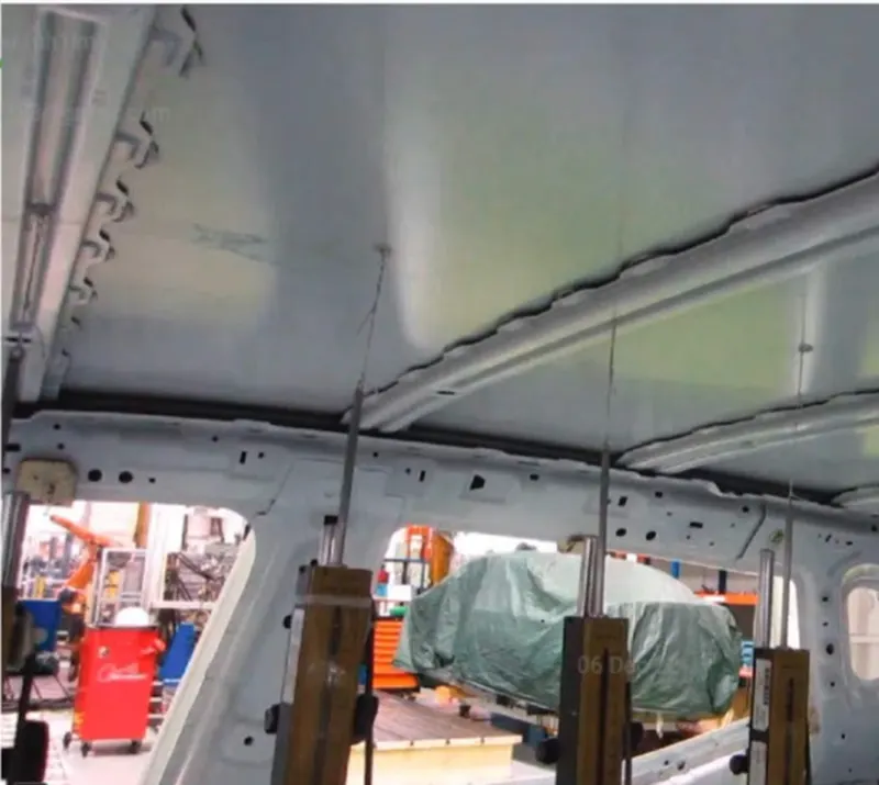
In this test, a metal plate is pneumatically forced downward onto the roof of a car.. The roof is crushed exactly five inches, and the force, which IIHS calls the strength-to-weight ratio, needed to do this is calculated. The more force needed to crush the roof five inches, the greater the likelihood that the car would perform well in a rollover.
The rating for the roof is given mainly based on two factors
- Time required for the roof structure to regain its original shape after the load has been removed
- The depth of protrusion in the roof caused b the load applied
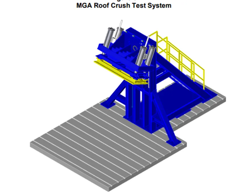
The metal plate is placed at an angle and also has certain standard dimension fixed by the IIHS which is obtained after a lot of research and analysis of the rollover and other incidents happening on road
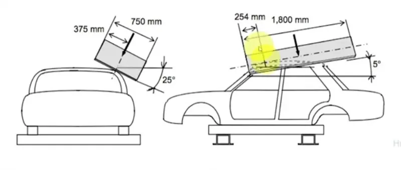
In order to proceed with the test there are three main conditions to be followed, which have been listed below:
- All the doors must be closed and in lock condition
- All the windows must be closed
- The car body must fixed on a rigid horizontal support system
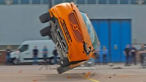
Roll over test
Rollover test is a type of destructive physical method of testing the structure of the car including the roof by rolling over the car at a certain speed simulating the case of a real life accident which can occur
Design for manufacture:
Draft angle
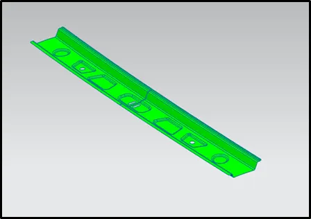
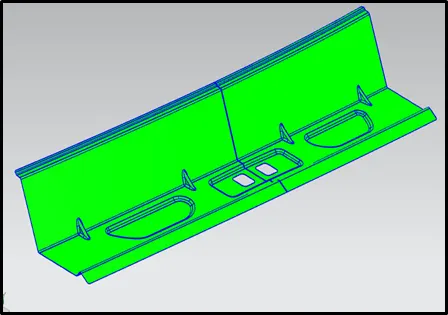
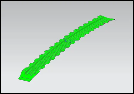
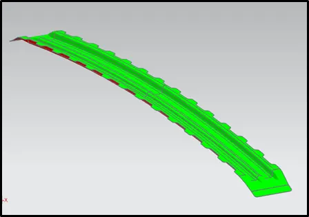
Positive draft angle is provided over all the surfaces of the inner panel to facilitate easy separation of the part and tool and reduce any chances of damage to the part during ejection. In most cases a minimum draft angle of 7 degrees is required for sheet metal components to ensure no problems occur during the processing of the sheet metal.
Mastic
Mastic sealants are basically gluing agents placed between the inner reinforcements and the roof outer panel. They are initially in liquid state when applied and are solidified once they are heated in the in the hot furnace. Mastics help increase the stiffness of the area in which it is placed and it also helps in reducing the NVH.A single mastic sealant covers a diameter of 80 mm and hence based on this the positions for mastics are decided and placed along the reinforcements.
Material
Material selection is one of the toughest and most important criteria for any product since it has a direct impact on the overall cost, safety, manufacturability, recyclability and the weight of the final product. Car roofs and its reinforcements are typically constructed from steel and sometimes from aluminium or their alloys.
Commonly used sheet metal operations:
Shearing:
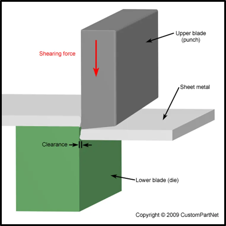
Shearing is performed by slicing through a piece of sheet metal with a blade that’s most often affixed to a tool or machine. The location of the cut is controlled by a squaring arm that allows a sheet of metal to be placed in a precise location.
Once the sheet metal is placed with the squaring arm, the top blade is lowered and compresses the metal against a lower blade, creating an exact cut.
Blanking:
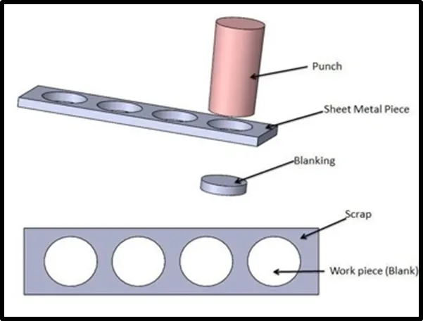
Blanking is a metal production process, during which a metal work piece is removed from the primary metal strip or sheet when it is punched. The material that is removed is the new metal work piece or blank. The metal strip is now the scrap.
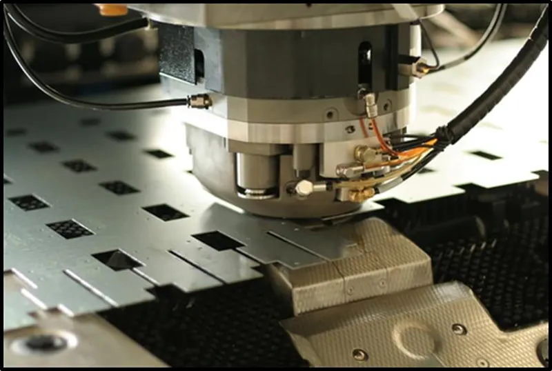
Punching:
Sheet metal punching is a cutting process in which material is removed from a piece of sheet metal by applying a great enough shearing force. CNC Punching can be used to produce holes and cutouts of various shapes and sizes
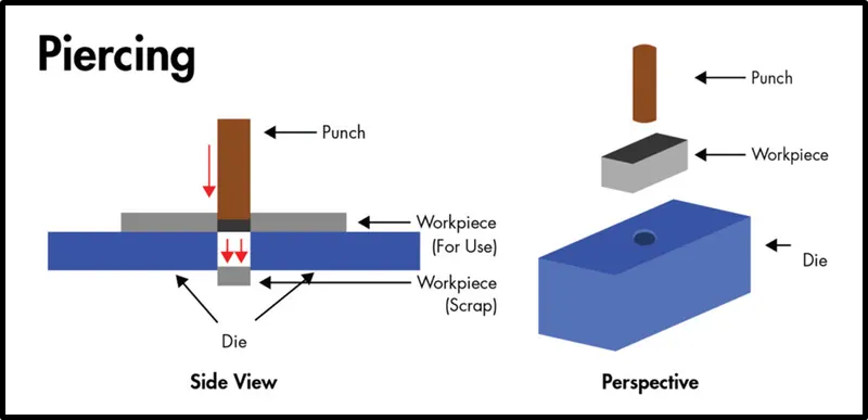
Piercing:
Piercing is a shearing process in which raw metal is pierced with a machining tool, resulting in the creation of a circular or other shaped hole. As the raw metal is pierced, the metal from the newly created hole is considered scrap
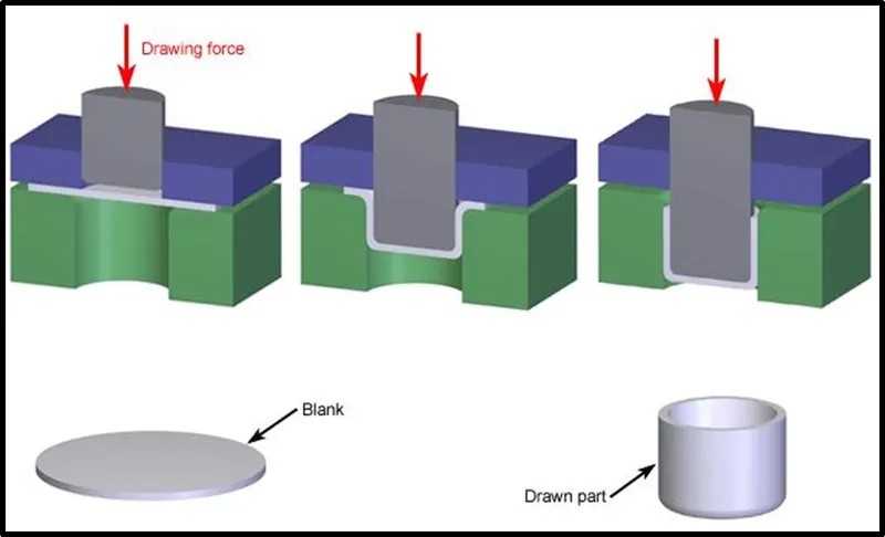
Deep drawing:
Deep drawing is a sheet metal forming process in which a sheet metal blank is radially drawn into a forming die by the mechanical action of a punch. It can also be called as a shape transformation process with material retention. The process is considered "deep" drawing when the depth of the drawn part exceeds its diameter.
Embossing:
Metal embossing is used to impart a design of different profiles upon metal sheets. The metal is pushed with an embossing tool or a punch in order to create a raised effect on the opposite side
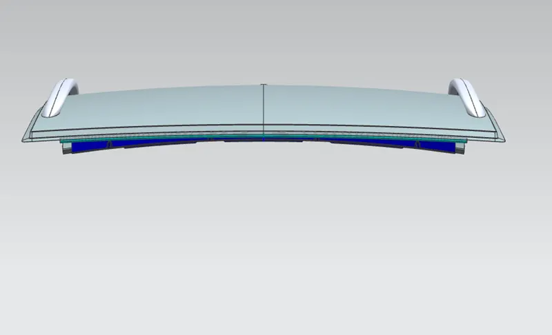
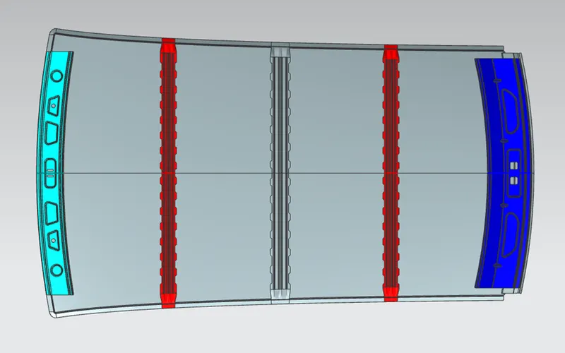
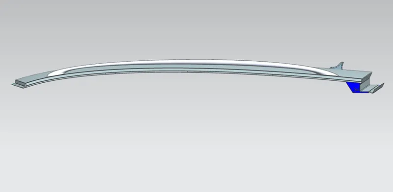
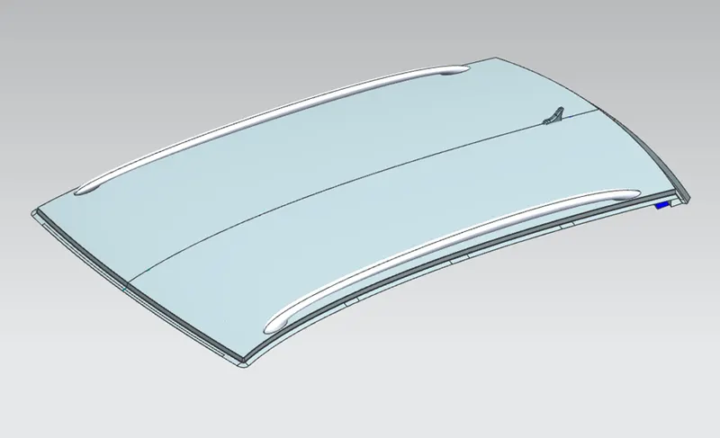
Final assembly
Front view
Top view
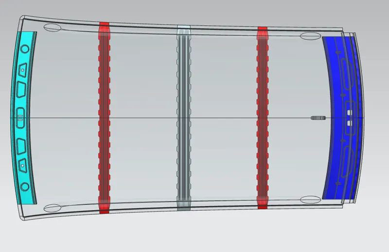
Bottom view
Side view
Isometric view
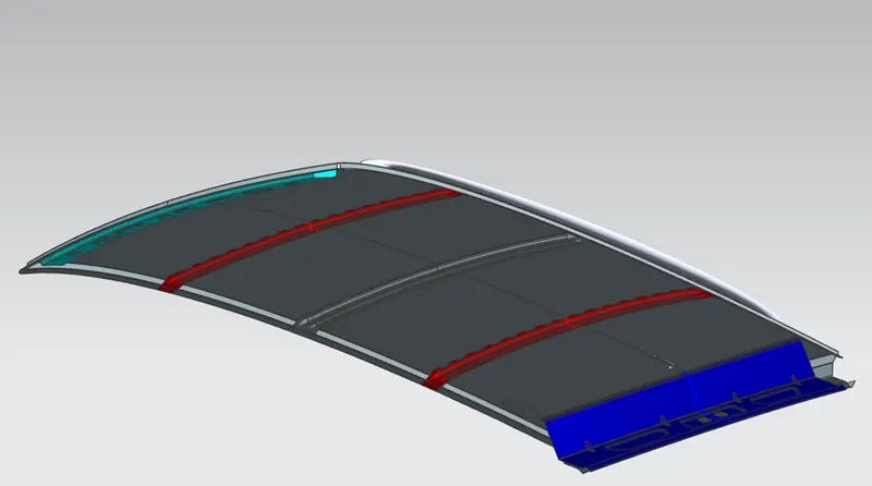
Conclusion:
- An assembly is created by developing the essential flanges for the outer roof and creating the necessary reinforcements for the outer panel
- appropriate dimensions according to the master section are provided
- The minimum draft angle criteria for all the parts using draft analysis is verified
- Calculations to determine the position of the Bow-roofs based on the heat distortion and snow load criteria are performed.