Roof Design
AIM: Using NX CAD, design a roof with all the components like front roof rail, rear roof rail, and bow roofs by following the given master sections and the skin data by considering all the design parameters.
Introduction
An automobile roof or car top is the portion of an automobile that sits above the passenger compartment, protecting the vehicle occupants from sun, wind, rain, and other external elements. The roof is not a single panel as seen from the exterior it consists of front roof rail, bow roofs, center roof rail, and rear roof rail with different thicknesses which act as a reinforcement for the top.
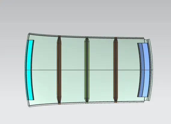
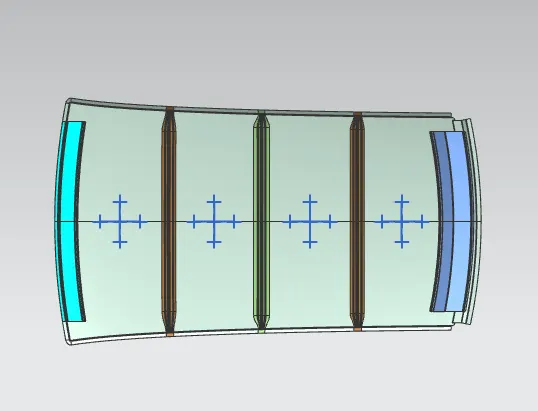
The below figure shows the elements included in the design of the Roof.
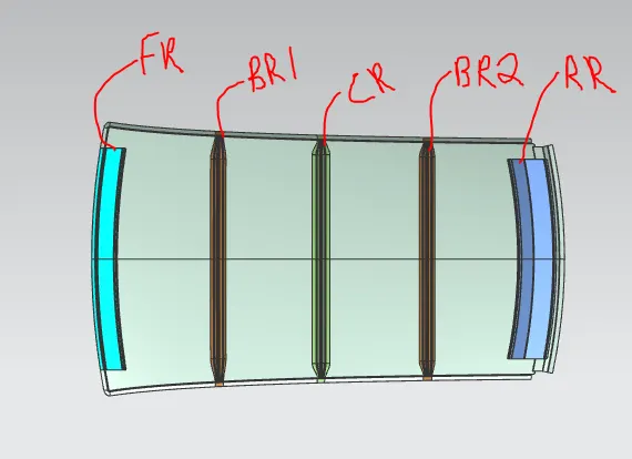
Here,
FR - Front Roof Rail
BR 1& BR 2 - Bow Roof 1&2
CR - Centre Roof Rail
RR - Rear Roof Rail
DESIGN OF FRONT ROOF RAIL
The front roof rail is created at the front side of the roof to provide strength to the roof. Headroom clearance and the driver visibility are the two important factors to be considered while designing the front roof rail.
The given Master Section for the Front Roof Rail is ,
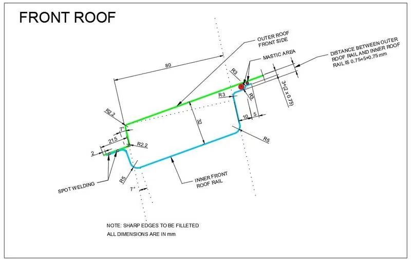
From the given master section we created the Front Roof Rail.
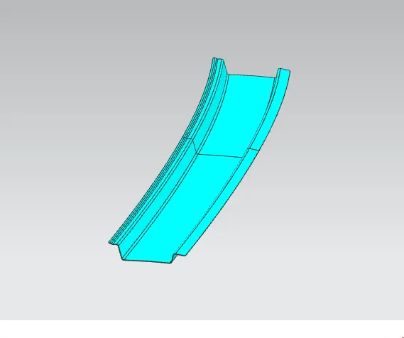
Draft Analysis of Front Roof Rail
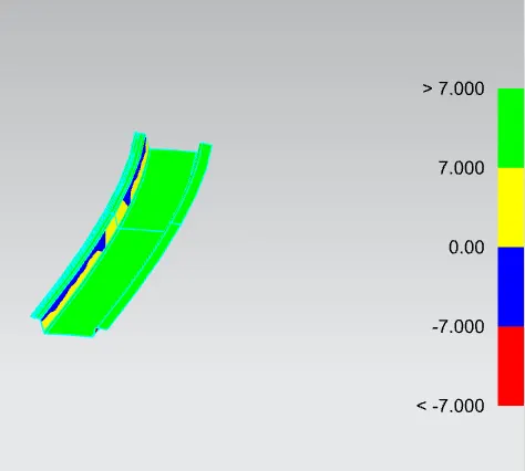
The designed Front Roof Rail is subjected to the draft analysis,and checked the given draft angle(7degree) clearing all the side of the component. Here the given draft angle is not clearing the component. The result is shown below,
DESIGN OF BOW ROOF
It is used to give strength to the area between the front and the centre roof rail. Also it is created in the area between the centre roof rail and the rear roof rail to provide enough strength. It can be created in any numbers depending up on the roof length but the position of the bow roofs is to be justified by the curvature study. Here we creating the 2 bow roof rails.
The Given master section for the Bow roof ,
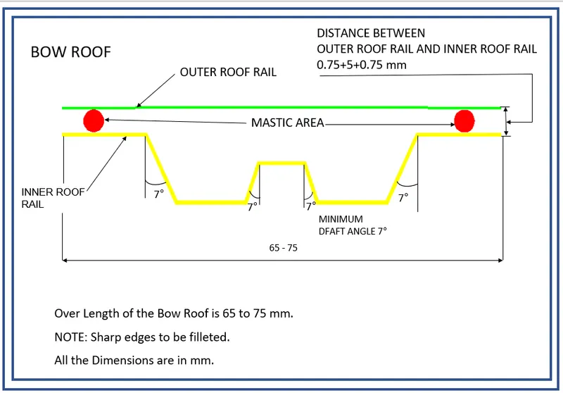
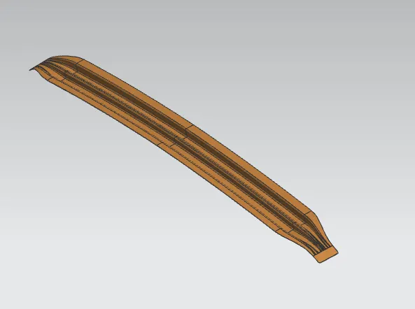
From the given master section we created the Bow roof
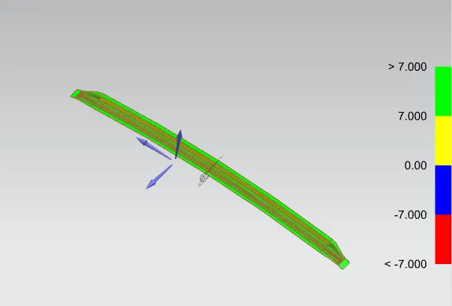
Draft Analysis of Bow roof
The designed bow roof is subjected to the draft analysis,and checked the given draft angle(7degree) clearing all the side of the component. Here the given draft angle is not clearing the component. The result is shown below,
DESIGN OF CENTRE ROOF RAIL
Central roof rail helps in providing effectively support to the flat area of the roof as it is more susceptible to failure under the action of load. Generally central roof rail is placed at the center of the roof which is connected to the B-pillar support structure. This central roof rail helps in the strength to the roof during the roll-over test.
The Given master section for Centre Roof Rail is
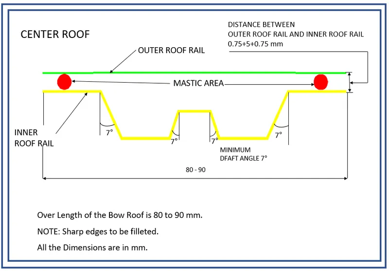
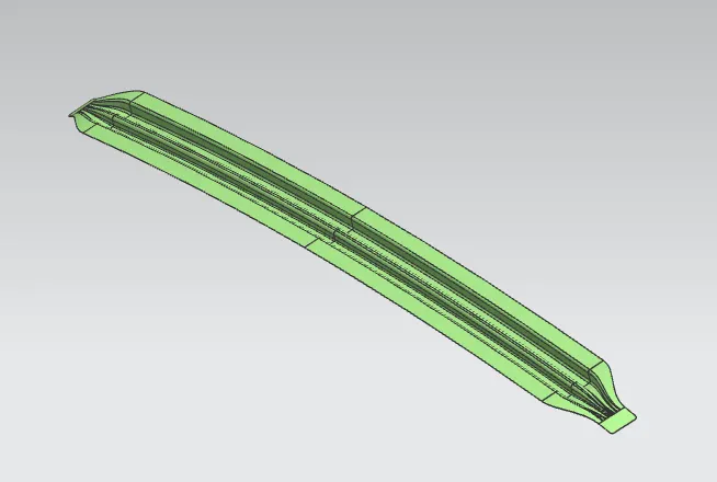
From the given master section we created the Centre Roof Rail,
Draft Analysis of Centre Roof Rail
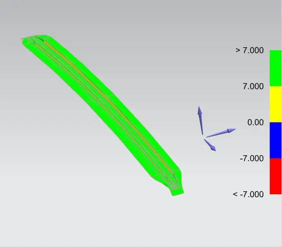
The designed centre roof rail is subjected to the draft analysis,and checked the given draft angle(7degree) clearing all the side of the component. Here the given draft angle is not clearing the component. The result is shown below,
DESIGN OF REAR ROOF RAIL
Same as the front rail roof, the rear rail roof provides reinforcement to the rear part of the car roof. Similar to the front rail roof, the rear roof rail is to be designed considering the rear visibility criteria and the rear passenger’s headroom clearance.
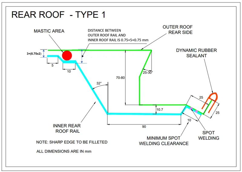
The Given master section for Rear Roof Rail is
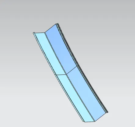
From the given master section we created the Rear Roof Rail,
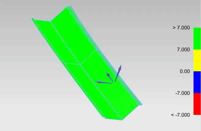
Draft Analysis of Centre Roof Rail
The designed Rear roof rail is subjected to the draft analysis,and checked the given draft angle(7degree) clearing all the side of the component. Here the given draft angle is not clearing the component. The result is shown below,
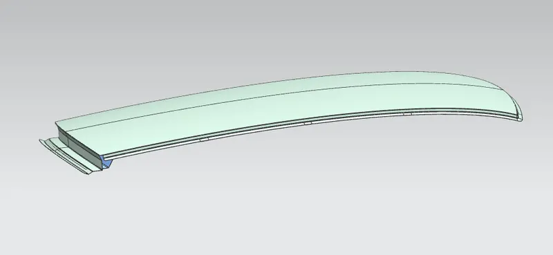
ROOF OUTER PANEL
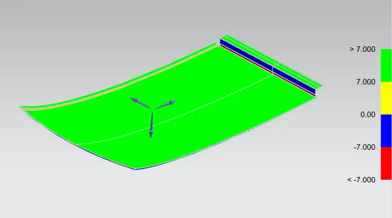
DRAFT ANALYSIS OF ROOF OUTER PANEL
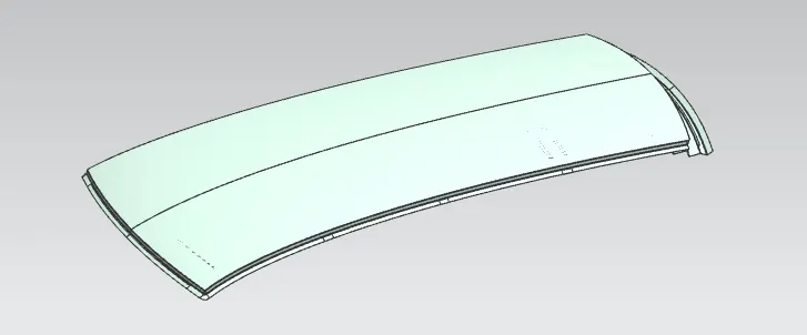
FINAL ROOM
The all the components are assembled to the roof outer panel ,
CALCULATIONS
1) HEAT DISTORTION CRITERIA
Heat distortion temperature is the temperature at which the metal softens and deforms under a specific load. This study is done to check the ability of the roof to withstand high temperatures concerning the positioning of the reinforcements which contribute to increased strength.
- FORMULA
W = [1.73 x 10^(-3) x L] + [1.85 x 10^(-8) x (R^2)/t] + [ 1.10x10^(-3) x l] - 2.68
Where,
L = Roof Length in X-Direction[mm](Roof dimension in 0-Y)
R = Roof curvature
R = 2(Rx*Ry)/(Rx+Ry)
Rx = X curvature
Ry = Y curvature
t = Roof plate thickness [mm]
l = Bow Roof Span [mm]
Judgment Condition
OK< 2.7
For the calculation we created some sketch to finding the value of variables in the above equation.
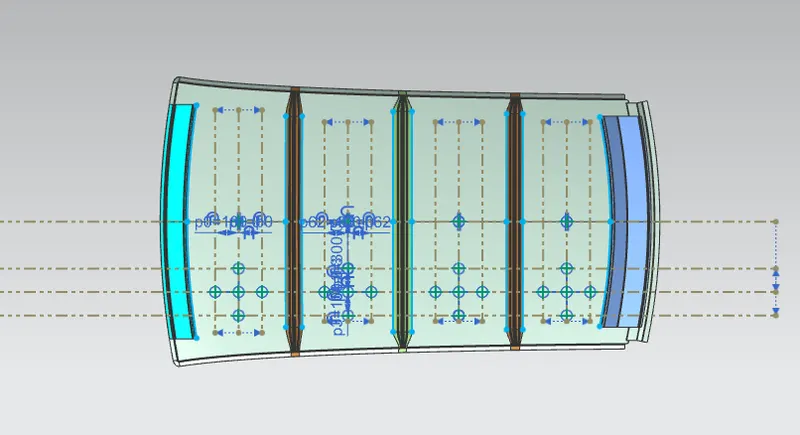
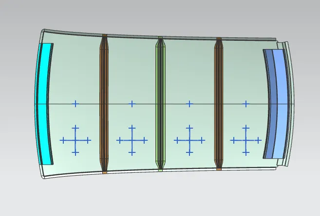
From the sektch we measured some variables and tabulated below
| SECTION | Rx | Ry | R | l | L | t |
W | Status |
| Front Rail to Bow Roof 1 | 5726.396 | 2720.902 | 3688.98 | 419.28 | 2029.403 | 0.75 | 1.62 | OK |
| Bow Roof 1 to Centre Roof | 4925.093 | 6382.998 | 5560.065 | 389.355 | 2029.403 | 0.75 | 2.02 | OK |
| Centre roof to Bow roof 2 | 4008.849 | 10373.4691 | 5782.88 | 403.44 | 2029.403 | 0.75 | 2.1 | OK |
| Bow Roof 2 to Rear Rail | 3306.190 | 14410.818 | 5378.44 | 373.49 | 2029.403 | 0.75 | 1.95 | OK |
From the above results, the positioning of the bow roofs satisfies the condition (OK Means W< 2.7) for Heat Distortion Criteria.
2) SNOW LOAD CRITERIA
A snow load study is done to check the ability of the roof to withstand snowfall and bounce back to its original position without undergoing permanent deformation upon the removal of the load.
Snow Load Prediction Formula
Qr = [Iy x t2] / [α x s x [(Rx + Ry)/2]2 x 10-8]
Note: The Qr value given over here is correct. There was a typo error in the formula given in the video.
Where,
α = My x Lx2 x 10-12 , My = Y(Ly-Y)
t = Roof plate thickness [mm]
Ly = Distance between the front and rear roof Rails on the Vehicle along with 0Y[mm]
Length of Roof panel with the center point between Roof rail Front /Rear as the front and rear reference point.
Lx = Distance between the Left and Right end of the roof on the Roof BOW [mm]
The width of the roof panel is exposed on the surface.
Y = Distance front Front Roof Rail to Roof BOW[mm]
s = Distance for which Roof BOW bears divided load [mm]
s = L1/2 + L2/2
Iy = Geometrical moment of inertia of Roof BOW (Y cross-section )[mm4]
Rx = Lateral direction curvature radius of roof panel Y cross-section on Roof BOW [mm]
Roof panel curvature Radius of the Length Lx in Front view
Ry = Longitudinal Direction curvature radius of the Roof panel X cross-section on Roof BOW [mm]
Roof panel X curvature radius of length s in Side view
Judgment condition
Qr ≥ 3.1
250 ≤ s ≤ 380
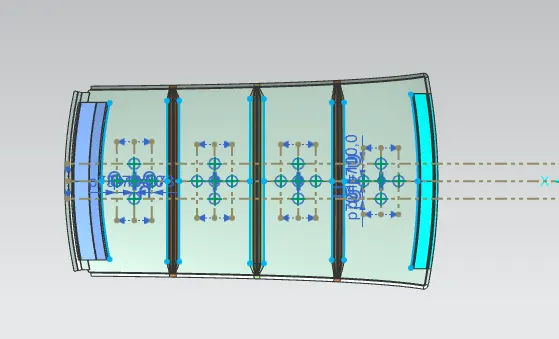
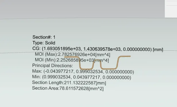
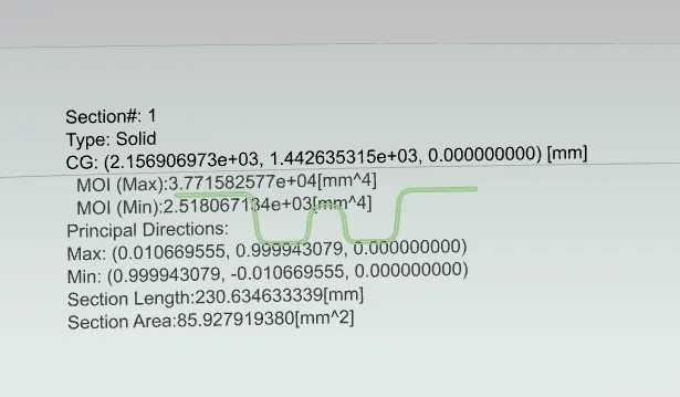
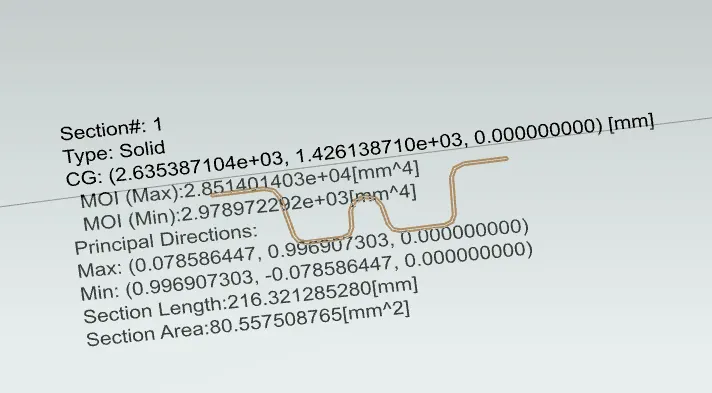
- For finding the unknown values in the above mentioned equation, we creating some sketches and also find the moment of interia of the components.
MOI OF BOW ROOF 1
MOI OF CENTRE ROOF RAIL
MOI OF BOW ROOF 2
| SECTION | Rx | Ry | Lx | Ly | Y | Iy | L1 | L2 | s | My | α(alpha) | t | Qr | OK/NOT |
| Front rail & Bow rail 1 | 4461.8281 | 2699.759 | 1105.94 | 2029.403 | 519.3 | 2252 | 519.3 | 464.14 | 491.72 | 784196.49 | .96 | 0.75 | 20.93 | OK |
| Bow Rail 1 & Centre Rail | 3771.8614 | 6269.687 | 1072 | 2029.403 | 981.423 | 2158 | 464.14 | 478.29 | 471.22 | 1028511.68 | 1.18 | 0.75 | 8.66 | OK |
| Centre Rail & Bow Rail 2 | 4260.806 | 10896.58 | 1052.59 | 2029.403 | 1457.182 | 2979 | 478.25 | 497.03 | 4897.66 | 833830.14 | .92 | 0.75 | 0.647 | NOT OK |
Hence we arrived to decision after result from calculation, one of the Qr result is not acceptable. So this model will pass over to the styling team to change the curvature to improve the strength or we can add some emboses to the top of the roof to improve the strength .
CONCLUSION
The roof has been successfully designed by considering all the design Rules and Master sections. Also, the curvature study is done by taking the heat distortion and snow load criteria for determining the strength of the roof.