Roof Design
ABOUT ROOF :-
The component of an automobile that lies above the passenger compartment and protects the occupants from the sun, wind, rain and other external elements is known as the roof or car top.
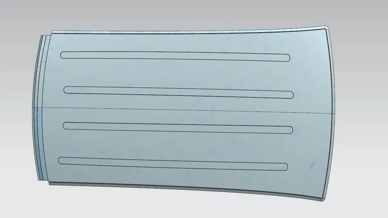
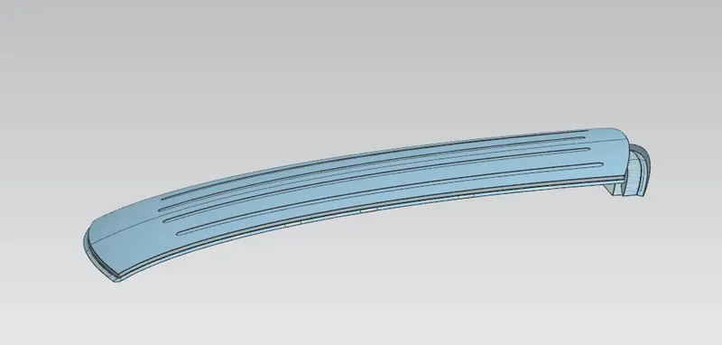
ROOF
AIM :-
Design of an automotive roof.
OBJECTIVE :-
1) Design roof outer.
2) Design front roof rail.
3) Design rear roof rail.
4) Design centre roof rail.
5) Design bow roofs.
6) Find moment of intertia of bow roofs.
7) Performs draft analysis on all the rails and bow roofs.
8) Check the roof for heat distortion criteria.
9) Check the roof for snow load criteria.
PARTS OF ROOF :-
1) Roof outer.
2) Front roof rail.
3) Rear roof rail.
4) Centre roof rail.
5) Bow roofs.
a) The roof has an outer panel which is styling part.
b) Strengthening parts are present below an outer panel of a roof, which are front roof rail, bow roof, centre roof rail and rear roof rail.
c) The front roof rail provides provison for the windshield glasses. Visibility criteria and headroom clearance have to be followed while designing the front roof rail. Provision for the windshield mounting and inside rearview mirror is provided on the front roof rail.
d) The rear roof rail has hinge mounting for the back door. It is attached at the portion where the back door metts with the roof.
e) Bow roofs are provided in between the front roof rail and centre roof rail as well as the rear roof rail and centre roof rail. They provide to enhance the localized the strenght of the roof and are attached directly to the bottom of the roof with either spot welding or with the help of mastics.
f) Reinforcements centre or centre roof rail is used as a cross member between left hand and right hand bodysides.
The below image show the location and material used for all the strengthening parts.
Design and functional requirements for the roof :-
While designeing of roof following cosideration have to be taken into acount.
Visibility criteria
Head clearence
Curvature Study
Heat distortion and snow load criteria.
Deign considerations :-
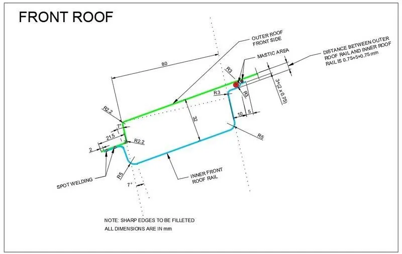
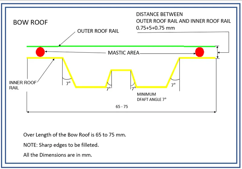
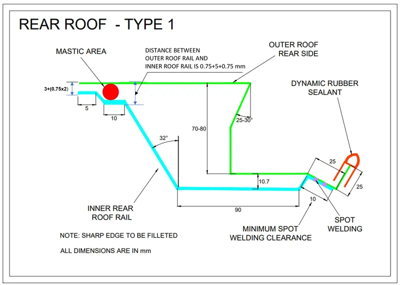
a) Clearence of 5mm should be present between outer roof rail and frontroof rail, rear roof rail, bow roof and reinforcement cenre where mastics are use for adhesion.
b) 0.75mm thickness for all sheet metals parts.
c) All edges should have fillets and there should not be any sharp edges present.
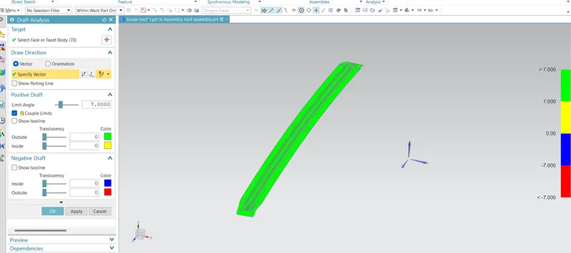
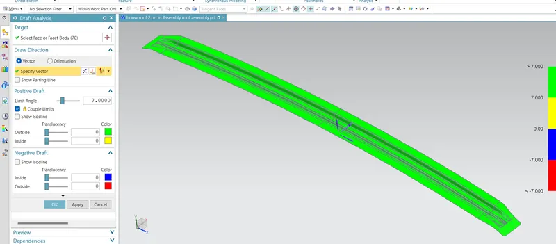
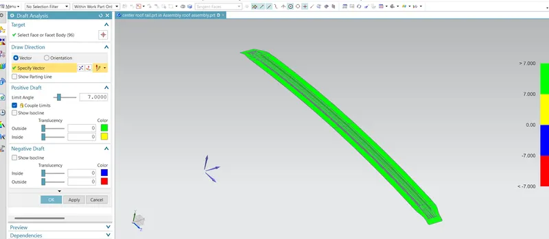
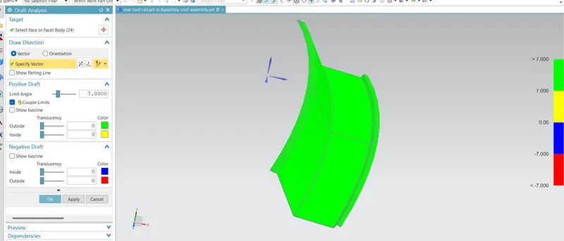
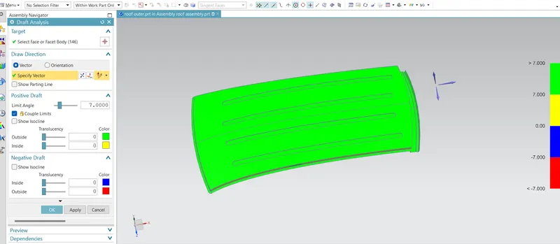
d) A minimum draft of 7 degrees is required for all the faces.
1) Design of front roof rail.
By following the give master section and dimensions front roof rail has been designed.
Master section of front roof rail.
Thickened part of the front roof rail.
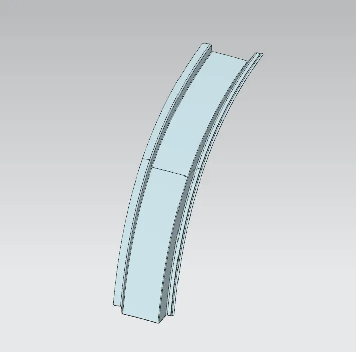
FRONT ROOF RAIL
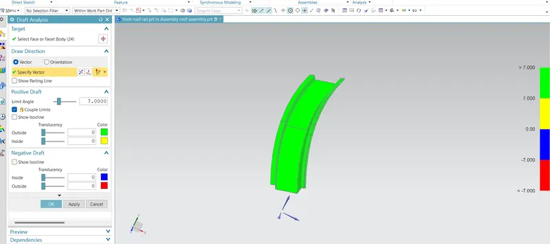
Draft analysis of front roof rail.
2) Design of bow roof 1 & 2
Master section of bow roof 1 & 2.
Thickened part of the bow roof 1 & 2.
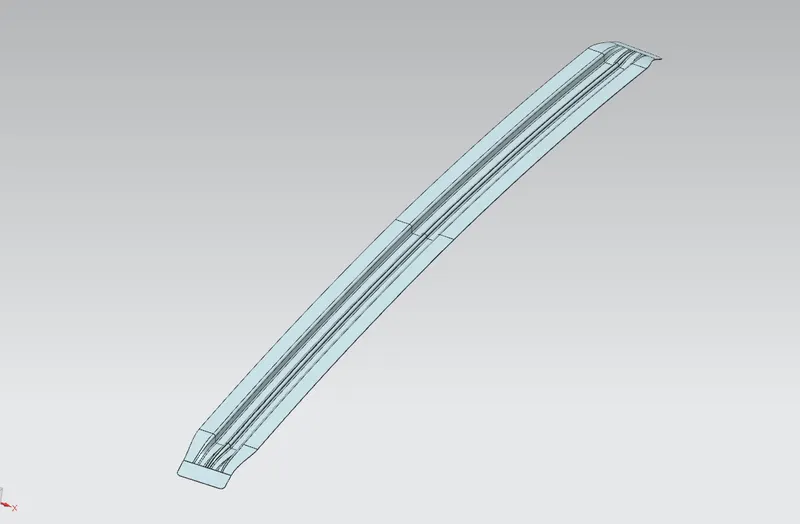
BOW ROOF 1
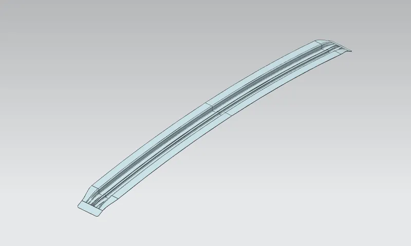
BOW ROOF 2
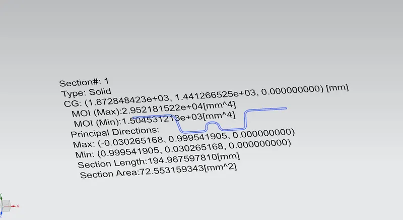
Section module of bow roof 1
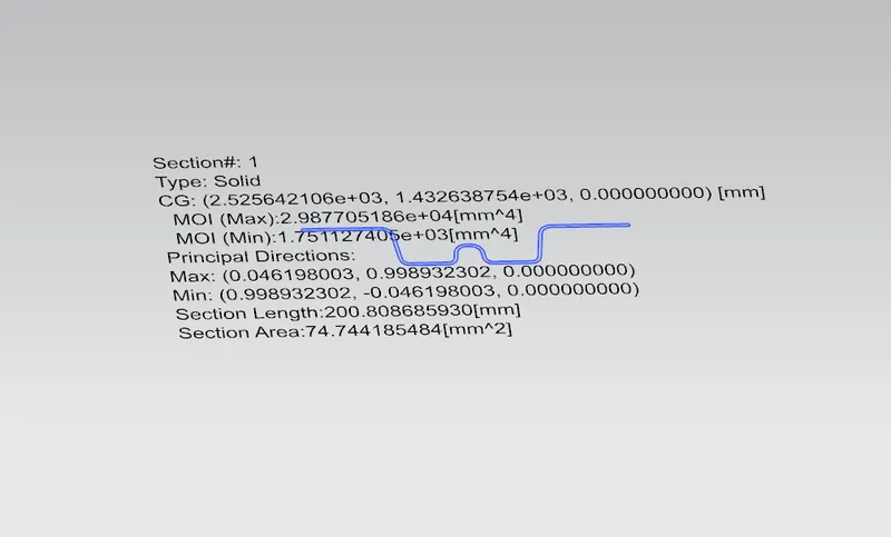
Section module of bow roof 2
Draft analysis of bow roof 1
Draft analysis of bow roof 2
3) Design of centre roof rail & reinforcement.
Master section of centre roof rail & reinforcement.
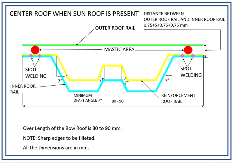
Thickened part of the centre roof rail & reinforcement.
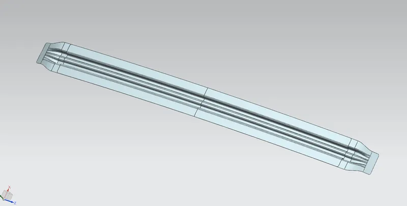
CENTRE ROOF RAIL & REINFORCEMENT
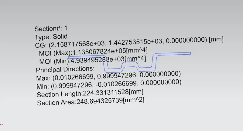
Section module of centre roof rail & reinforcement.
Draft analysis of centre roof rail & reinforcement.
4) Design of rear roof rail.
Master section of rear roof rail.
Thickened part of the rear roof rail.
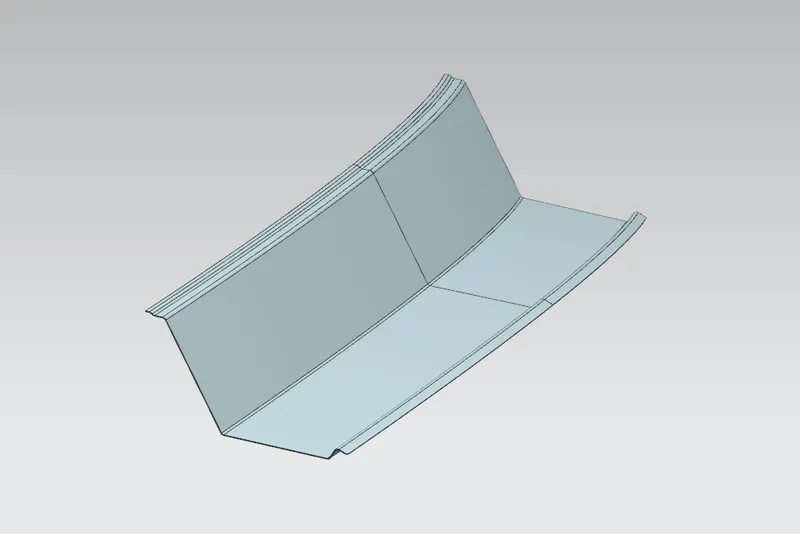
REAR ROOF RAIL
Draft analysis of rear roof analysis.
5) Design of roof outer.
As per shown in master section of front roof rail and rear roof rail design the roof outer.
ROOF OUTER
Draft analysis of roof outer.
HEAT DISTORTION ANALYSIS :
Heat distortion analysis plays a pivotal role in the strength of the roof panel. It is the temperature above which material cannot be used for structural applications.
This study is used to predict the heat distortion temperature where the material starts to soften when exposed to a fixed load at elevated temperature.
In order to avoid any bending or damages on the roof, heat distortion temperature can be recalculated using the trail and error method by changing the position of bow roof. In this way, it can come in the range which is shown in below.
FORMULA :
W = [1.73 x 10^(-3) x L] + [1.85 x 10^(-8) x (R^2)/t] + [1.10 x 10^(-3) x l] - 2.68
Where,
L = roof length in X-Direction (mm) (roof dimension in 0-Y)
R = roof curvature
R = 2(Rx X Ry)/(Rx+Ry)
Rx = X curvature
Ry = Y curvature
t = roof plate thickness [mm]
l = Bow roof Span [mm]
JUDGMENT CONDITION
OK < 2.7
Drawing for heat distortion analysis.
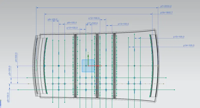
Calculation :
| SR NO | BOW position | Rx | Ry | R | l | L | t | W | OK/NG |
| 1 | RR & 2BR | 3382.8048 | 13923.6451 | 5443.169888 | 432.677 | 2033.2 | 0.75 | 2.044207128 | OK |
| 2 | 2 BR & CTR | 4095.9899 | 9986.9979 | 5809.369874 | 283.83211 | 2033.2 | 0.75 | 1.982121176 | OK |
| 3 | CTR & 1 BR | 4743.2533 | 7118.7342 | 5693.136919 | 202.5713 | 2033.2 | 0.75 | 1.859755694 | OK |
| 4 | 1 BR & FR | 5645.1607 | 3309.3286 | 4172.586762 | 556.727 | 2033.2 | 0.75 | 1.879294214 | OK |
The roof design has successfully cleared the heat distortion analysis.
SNOWLOAD ANALYSIS :
The purpose behind this analysis is to check the strength of the roof when snow is present on it acting as a load.
A roof should be designed in such a way that it should rebound to its original shape after the removal of snow.
FORMULA
Qr = [Iy x t^(2)] / [α x s x (((Rx + Ry) / 2)^2) x 10^(-8)]
α = My x Lx^(2) x 10^(-12) , My = Y(Ly-Y)
t = roof plate thickness [mm]
Ly = Distance between the front and rear roof rails on the vehicle along with 0Y[mm]
Length of roof panel with the center point between roof rail front / rear as the front and rear reference point.
Lx = Distance between the left and right end of the roof on the roof bow [mm]
The width of the roof panel is exposed on the surface.
Y = Distance front front roof rail to roof bow[mm]
s = Distance for which roof bow bears divided load [mm]
s = L1/2 + L2/2
Iy = Geometrical moment of inertia of roof bow (Y cross-section )[mm4]
Rx = Lateral direction curvature radius of roof panel Y cross-section on roof bow [mm]
roof panel curvature radius of the length Lx in front view.
Ry = Longitudinal direction curvature radius of the roof panel X cross-section on roof bow [mm]
roof panel X curvature radius of length s in side view.
JUDGMENT CONDITION
Qr ≥ 3.1
250 ≤ s ≤ 380
Drawing for Snowload analysis.
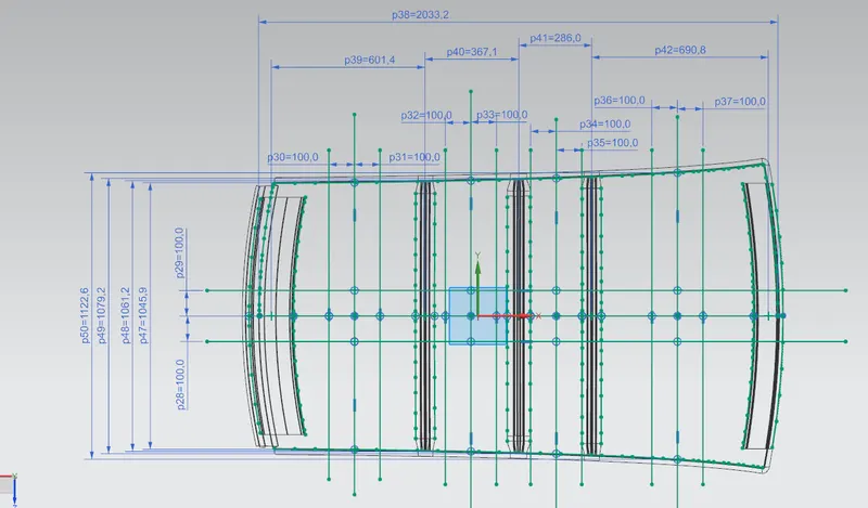
Calculation :
| SR NO | BOW Position | Rx | Ry | Lx | Ly | Iy | Y | t | My | α | L1 | L2 | s | Qr | OK/NG |
| 1 | RR & 2BR | 4150.1733 | 15469.7814 | 1045.9 | 2033.2 | 1504.5 | 601.4 | 0.75 | 861084.52 | 0.94194622 | 601.4 | 367.1 | 484.25 | 1.92789320 | NG |
| 2 | 2 BR & CTR | 4212.5367 | 10343.1415 | 1061.2 | 2033.2 | 4939.4 | 968.5 | 0.75 | 1031161.95 | 1.161238 | 367.1 | 286 | 326.55 | 13.83314007 | OK |
| 3 | CTR & 1 BR | 3836.1912 | 7087.0226 | 1079.2 | 2033.2 | 1751.1 | 1254.5 | 0.75 | 976879.15 | 1.137744418 | 286.0 | 690.8 | 488.4 | 5.942541575 | OK |
| 4 | 1 BR & FR | 4145.9975 | 3288.9343 | 1122.6 | 2033.2 | NA | 1945.4 | 0.75 | 170806.12 | 0.215255126 | 690.8 | NA | NA | NA | NA |
Now, as we seen in 1st case the value for snow load it does not satisfy the condition.
So to make the roof stronger we have to create embosses on the top of the roof.
CONCLUSION :
The roof has been successfully designed, considering all the design rules, master sections, manufacturing feasibility, draft analysis, heat distortion criteria and snowload analysis.