Roof Design
Aim- To design the roof and develop the essential flanges and reinforcements, as well as check for draught analysis and section modulus reports on the 0-Y section.
Introduction
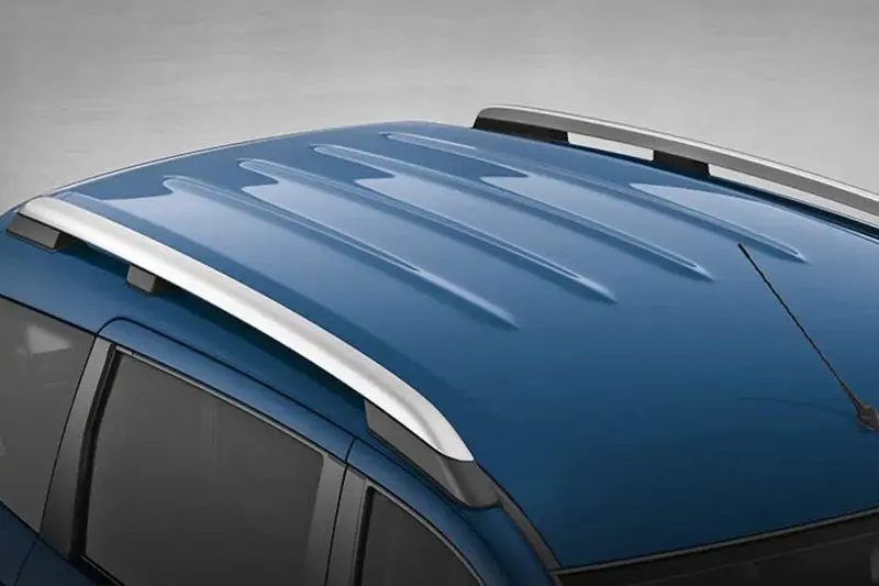
The component of a car that lies above the passenger compartment and protects the occupants from the sun, wind, rain, and other exterior factors is known as the roof. Though it appears to be a stylish surface that shields from the sun, wind, and other elements, it is designed with diverse environmental conditions in mind. Roof reinforcements should be installed to strengthen it. The vehicle roof may be subjected to high temperatures or weight during snowy conditions. Various calculations are performed to ensure that the roof can survive these circumstances. This assures the passengers' safety in the vehicle.
Objective
- The goal of this project is to build a car roof with necessary flanges and reinforcements such as ditch area, front roof rail, bow roofs, centre roof rail, and rear roof rail for the provided stylistic surface.
- To establish if the bow roofs are in the proper places, do a curvature research on the roof and calculate the heat distortion and snow load criterion.
- Finding the moment of inertia and section modulus of a bow roof with a central roof rail. Roof rails on both the front and back sides.
- Conduct a draught analysis for each reinforcement.
WHY REINFORCEMENTS:
Because a flat roof is exceedingly fragile and cannot withstand pressures such as snow, reinforcements such as front roof rails, centre roof rails, rear roof rails, and bow roofs are introduced and linked to the flat surface of the roof with various joining methods.
DESIGN CONSIDERATION OF ROOF:
- Visibility criteria
- Head room clearance
- Bow roof position
- Heat distortion and Snow load criteria
- Draft analysis
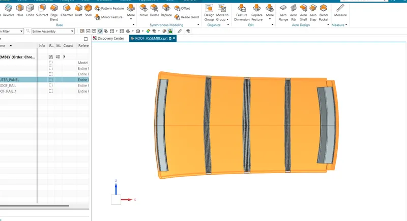
Front Roof rail
The front roof rail connects the wind shield glass, body side outer and inner panels. The front roof rail is created based on the master section provided.
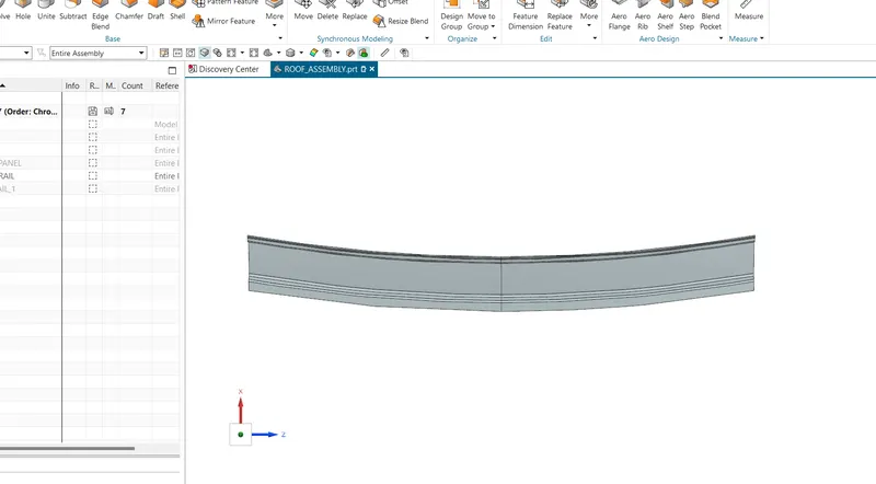
Rear Roof Rail :
Rear roof rail is the one which joins the back door and the body side outer
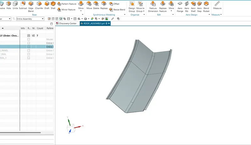
CENTRAL BOW ROOF RAIL :
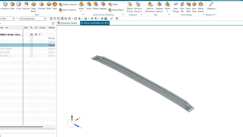
The centre roof rail aids in giving appropriate support to the flat part of the roof, which is more prone to failure due to load action. In most cases, a central roof rail is installed in the middle of the roof and is attached to the B-pillar support system. During the rool-over test, this central roof rail adds strength to the roof.
BOW ROOFS :
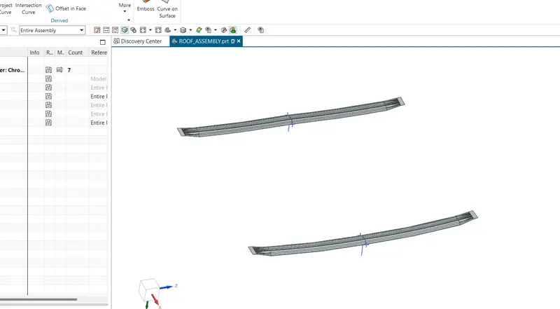
Bow roofs are used to increase the roof structure's torsional rigidity and load carrying capability. The amount of bow roofs that are present is determined by the total size of the roof. Two bow roofs are currently being added to this project.
APPLICATION PROCESS:
Mastics are placed between the outer panel of the roof and the reinforcements for connecting. Wherever the mastic is administered, the strength improves noticeably.
Spot welding is also used to connect the reinforcements to the outer panel.
TEST FOR ROOF CRUSH:
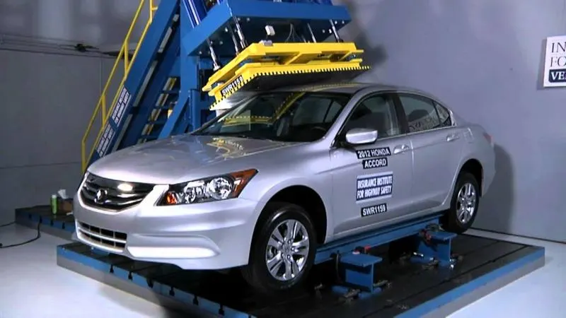
The IIHS (insurance institute of highway safety) designed the roof crush test. After reviewing the numerous incidents, the IIHS established certain guidelines for conducting the crush test.
Based on the results of this test, the IIHS assigns a rating. When determining the rating, they take into account two factors.
How quickly the automobile returns to its former configuration following a rollover and what is the depth of the protrusion following the roll over.
THE FOLLOWING ARE THE ROOF CRUSH TEST CONDITIONS:
For the roof crush test, there are two requirements that must be met:
INITIAL CONDITION:
All of the doors should be closed and locked.
All of the windows should be closed.
SECOND REASON:
Place the body sill or chassis frame horizontally on a firm lever surface.
FORCE APPLICATION METHOD:
The weight is placed in such a way that 50 is inclined from the front to the back, and the load is 1800 mm long and 750 mm wide. The weight is applied at a distance of 250 from the roof's flatness. The force is delivered to the roof for nearly 120 seconds, and the crush speed at which the load is applied is 13 mm/sec or less.
If the displacements exceed the required level, we must raise the thickness of the bow roof or add additional mastics points to boost the strength. The stronger the roof, the better it protects the occupants in rollover accidents.
HEAT DISTORTION STUDY ON THE ROOF :
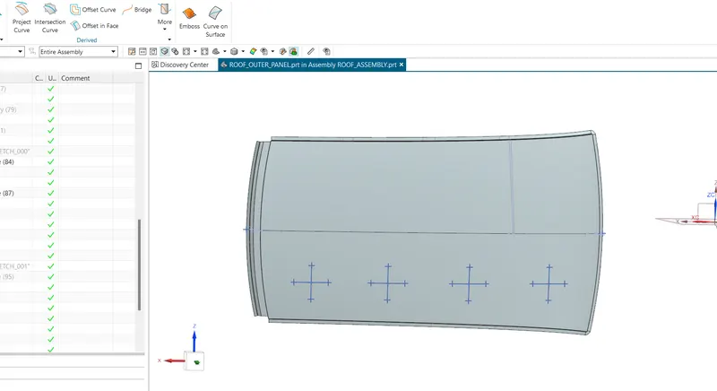
The heat distortion study is important in the use of sheet metal. The heat distortion temperature is a temperature limit over which the material cannot be used for structural purposes. This study is used to anticipate the heat distortion temperature at which the material begins to soften when subjected to a constant load at an increasing temperature. To minimise bending or damage to the roof, this study will anticipate the bow roof position based on the heat distortion temperature, which helps to reinforce the roof.
Bow – roof prediction Formula
W = [1.73 x 10^(-3) x L] + [1.85 x 10^(-8) x (R^2)/t] + [ 1.10x10^(-3) x l] - 2.68
Where
L = Roof Length in X-Direction[mm](Roof dimension in 0-Y)
R = Roof curvature
R = 2(Rx*Ry)/(Rx+Ry)
Rx = X curvature
Ry = Y curvature
t = Roof plate thickness [mm]
l = Bow Roof Span [mm]
Judgement Condition : OK< 2.7> 3.1
APPLY THE VALUES IN THE FORMULA :
In order to find the heat distortion apply all the necessary values from the roof to the give formula
| Position | L (mm) | Rx (mm) | Ry (mm) | R Imm) | l (mm) | t (mm) | W | judgment |
| FRR & BR1 | 2033.7 | 2741.8 | 5724.5 | 3707.67 | 449.59 | 0.75 | 1.67 | ok |
| BR1 &CRR | 2033.7 | 6573.36 | 4877.66 | 5599.95 | 387.84 | 0.75 | 2.038 | ok |
| CRR & BR2 | 2033.7 | 10688.3 | 3957.42 | 5776.17 | 405.81 | 0.75 | 2.1076 | ok |
| BR2 & RRF | 2033.7 | 14569.9 | 3281.9 | 5357.1 | 350 | 0.75 | 1.9311 | ok |
According to the preceding table, all values of w2.7 and no w>3.1 indicate that the current bow row alignment is satisfactory in state and judged to be acceptable.
CRITERIA FOR SNOW LOAD:
This test is performed to determine how the roof behaves when there is snow on it. The dent is usually caused by the weight of the snow. However, the roof should be built so that after the snow is removed, the roof returns to its original position. This is the fundamental criterion for snow load criteria.
Qr = [Iy x t2] / [α x s x [(Rx + Ry)/2]2 x 10-8]
Where
α = My x Lx2 x 10-12 , My = Y(Ly-Y)
Judgement condition = Qr ≥ 3.1
250 ≤ s ≤ 380
t = Roof plate thickness [mm]
Ly = Distance between the front and rear roof Rails on the Vehicle along with 0Y[mm]
Length of Roof panel with the center point between Roof rail Front /Rear as the reference point of the front and the rear.
Lx = Distance between the Left and Right end of the roof on the Roof BOW [mm]
Width of the roof panel exposed on the surface.
Y = Distance front Front Roof Rail to Roof BOW[mm]
s = Distance for which Roof BOW bears divided load [mm]
s = L1/2 + L2/2
Iy = Geometrical moment of inertia of Roof BOW (Y cross-section )[mm4]
Rx = Lateral direction curvature radius of roof panel Y cross-section on Roof BOW [mm]
Roof panel curvature Radius of the Length Lx in Front view
Ry = Longitudinal Direction curvature radius of the Roof panel X cross-section on Roof BOW [mm]
APPLY THE VALUES IN THE FORMULA :
In order to find the snow load criteria apply all the necessary values from the roof to the give formula
CALCULATIONS :
| Position | ly | Alpha | My | Lx | Ly | Y | s | Rx | Ry | t | Qr | Judgment |
| FRR & BR1 | 1676.8 | 0.9857 | 767554 | 1133.24 | 1955.2 | 543.84 | 504.575 | 2778.13 | 4411.91 | 0.75 | 14.68 | ok |
| BR1 & CRR | 2093.2 | 1.12 | 954843 | 1083.4 | 1955.2 | 1006.9 | 474.3 | 6498.47 | 3786.07 | 0.75 | 8.38 | ok |
| CRR & BR2 | 1691.05 | 0.778 | 695703.8 | 1057.6 | 1955.2 | 1487.5 | 479.346 | 11213.73 | 4284.29 | 0.75 | 33.66 | ok |
Section analysis:
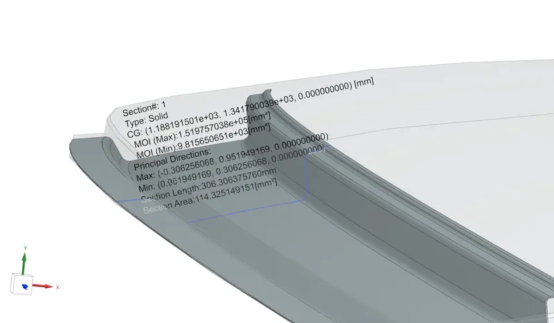
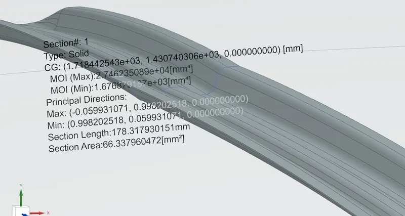
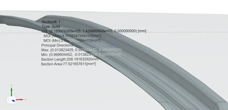
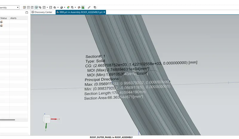
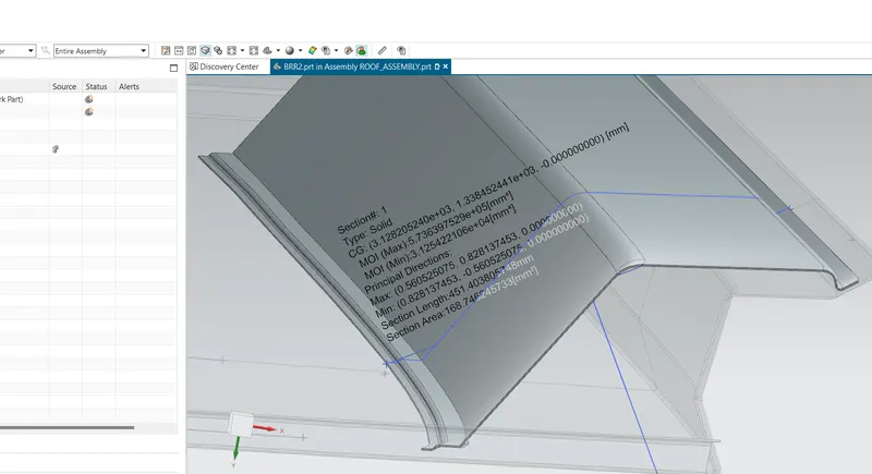
The section moment of inertia is used to anticipate how much a component will bend and deflect. A larger moment of inertia is preferred since it minimises deflection for a given force. The inclusion of flanges and embosses, as well as the thickness of the component, enhance the section inertia of the part. The master sections of the roof and roof rails, as well as their section analysis, are provided here.
FRONT ROOF RAIL
Create an intersection curve with the help of the plane and select the face of foor rail then apply section inertia analysis. if section innertia analysis is not getting then slecct the sketch and plane projet the curve and perform section inertia analysis
Bow Roof Rail
Center Roof Rail
Rear Bow Roof Rail
Real Roof Rail
DRAFT ANALYSIS:
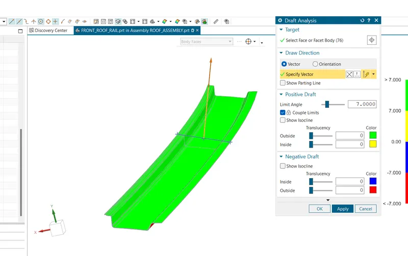
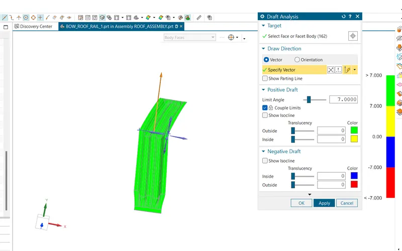
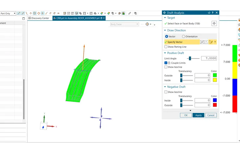
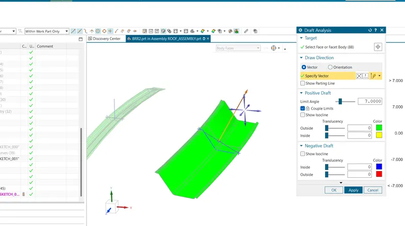
The Draft Analysis command determines if the portion you drafted can be readily deleted. This method of analysis is based on colour ranges that define zones on the investigated element where the deviation from the draught direction corresponds to specified values at any location.
For analysis, a minimum draught angle of 70 is used. Green colour indicates that all faces along the tooling direction have a positive draught angle greater than 70 and have passed analysis.
DRAFT ANALYSIS FOR FRONT ROOF RAIL :
DRAFT ANALYSIS FOR BOW ROOF RAIL 1:
DRAFT ANALYSIS FOR CENTRAL ROOF RAIL :
DRAFT ANALYSIS FOR BOW ROOF RAIL 2:
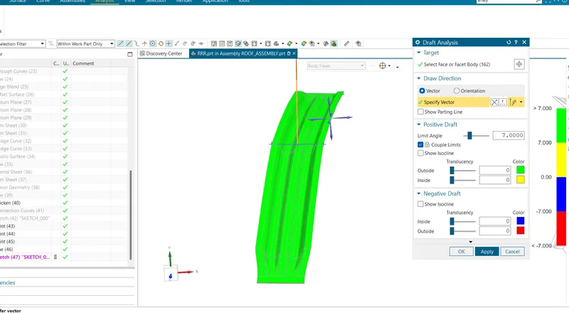
DRAFT ANALYSIS FOR REAR ROOF RAIL :
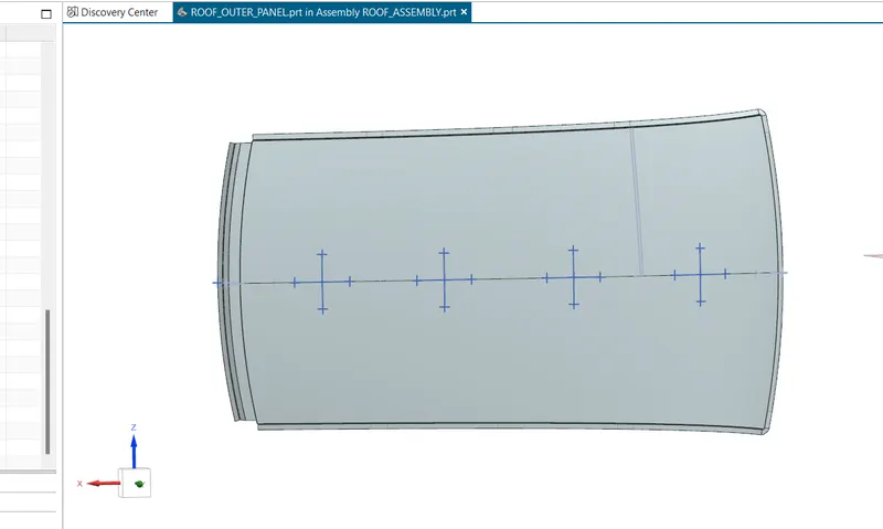
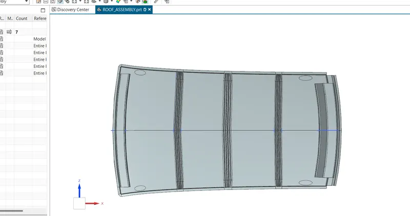
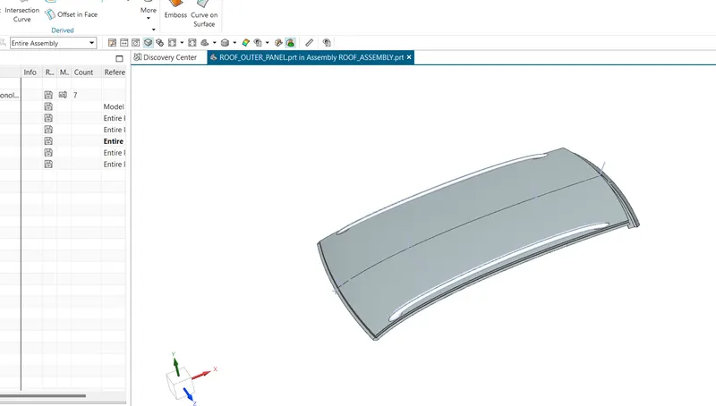
ROOF IMAGES :
NOTE:
THE BOW ROOF 1 AND CENTRE ROOR IS LOOKING INCLIND IS BECAUSE OF THE SOFTWARE GRAPHICAL ISSUE